60
What is MOBILE COMMUNICATION?? • What’s Mobility ??? • Does it really mean anything on a go ??? • What’s Communication ???
| Date post: | 04-Jun-2018 |
| Category: |
Documents |
| Upload: | tahir-hussain |
| View: | 219 times |
| Download: | 0 times |

8/13/2019 Into to Communication Systems Chap 2
http://slidepdf.com/reader/full/into-to-communication-systems-chap-2 1/60
What is MOBILE COMMUNICATION??
•
What’s Mobility ???• Does it really mean anything on a go ???
• What’s Communication ???
8/13/2019 Into to Communication Systems Chap 2
http://slidepdf.com/reader/full/into-to-communication-systems-chap-2 2/60
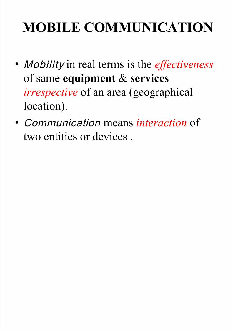
MOBILE COMMUNICATION • Mobility in real terms is the effectiveness
of same equipment & services irrespective of an area (geographical
location).
• Communication means interaction oftwo entities or devices .

8/13/2019 Into to Communication Systems Chap 2
http://slidepdf.com/reader/full/into-to-communication-systems-chap-2 3/60
What is CELL & BTS
• Cell is a geographical area in which a clear radio Signal from
one BTS can be sensed.
• Base Transceiver Station is tall tower with antennas at the top &
necessary electronics to generate & manipulate the signals.

8/13/2019 Into to Communication Systems Chap 2
http://slidepdf.com/reader/full/into-to-communication-systems-chap-2 4/60
Diff b/w Cellular & Non Cellular
Communication
• In Non Cellular (e.g. radio) Communication a single high
power Transmitter used to cover a wide range of area.
• Cellular Communication network is composed of number of
small cel ls . The reasons are
1. radio signals at the frequencies used for cellular Comm travel
only a few ki lometers from the point at which they are
transmitted.
2. They travel more or less equal distances in all directions;
hence, the area around it where a radio signal can be received
is typically approximately circular .

8/13/2019 Into to Communication Systems Chap 2
http://slidepdf.com/reader/full/into-to-communication-systems-chap-2 5/60
Diff b/w Cellular & Non Cellular
Communication cont’d • If the network designer wants to cover a large area, then he must
have a number of transmitters positioned so that when one gets tothe edge of the first cell there is a second cell overlapping slightly,
providing radio signal.
• Hence the construction of the network is a series of approximately
circular cells
8/13/2019 Into to Communication Systems Chap 2
http://slidepdf.com/reader/full/into-to-communication-systems-chap-2 6/60

8/13/2019 Into to Communication Systems Chap 2
http://slidepdf.com/reader/full/into-to-communication-systems-chap-2 7/60
What are the motivations for this?
The aim is to use spectrum or bandwidth efficiently .
Bandwidth allocation for voice channels (and data) is
limited .
Each cell allows one to use a number of radiochannels.
Adjacent cells use different frequencies.
Each cell has a control channel.
A call started in one zone has to be re-initiated whenmoving to a new zone because the call will bedropped .

8/13/2019 Into to Communication Systems Chap 2
http://slidepdf.com/reader/full/into-to-communication-systems-chap-2 8/60

8/13/2019 Into to Communication Systems Chap 2
http://slidepdf.com/reader/full/into-to-communication-systems-chap-2 9/60
Why Cells Theoretically made Hexagons ??
• The actual radio coverage is known as the
footprint .
• It is determined from the field measurements or
propagation prediction model.
• The real footprint is amorphous in nature.

8/13/2019 Into to Communication Systems Chap 2
http://slidepdf.com/reader/full/into-to-communication-systems-chap-2 10/60
Area of a Hexagon
• What is the Area of hexagon in terms of R???
• Hint:
s = R
s ┴ h R
10

8/13/2019 Into to Communication Systems Chap 2
http://slidepdf.com/reader/full/into-to-communication-systems-chap-2 11/60
Frequency Reuse
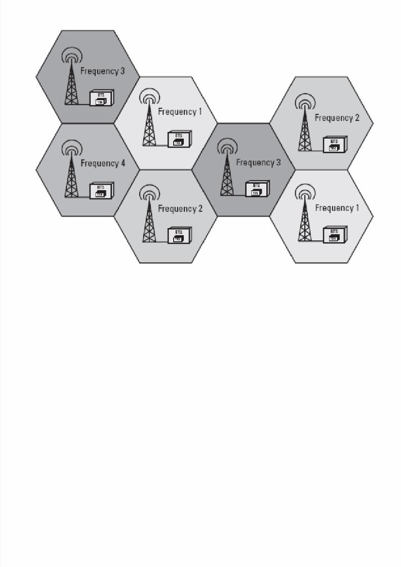
• Each cell is assigned a part of the availablefrequency spectrum.
• Cellular radio systems offer the possibility ofusing the same part of the frequency spectrummore than once.
• This is called frequency reuse.
•Cells with identical channel frequencies are calledco-channel cells.
• The co-channel cells have to be sufficientlyseparated to avoid interference.

8/13/2019 Into to Communication Systems Chap 2
http://slidepdf.com/reader/full/into-to-communication-systems-chap-2 12/60
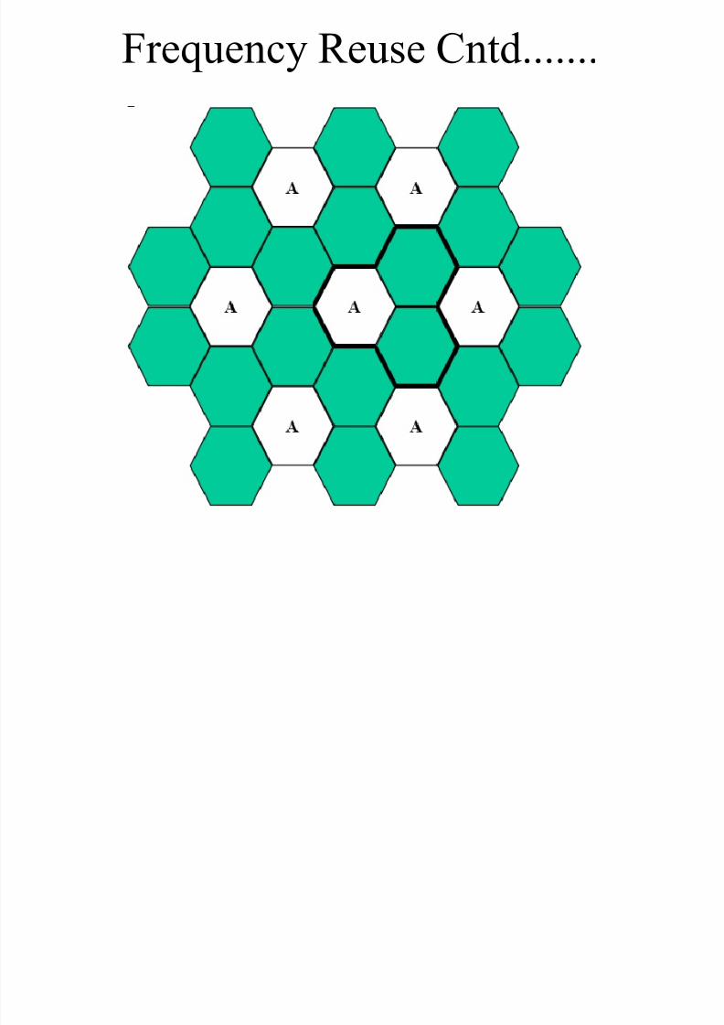
Frequency Reuse Cntd.......
• The distance between
these co-channel cells is
achieved by the creation
of a cluster of cells.
• The cells which
collectively use the
complete set of
available frequencies iscalled a cluster.

8/13/2019 Into to Communication Systems Chap 2
http://slidepdf.com/reader/full/into-to-communication-systems-chap-2 13/60
Frequency Reuse Cntd....... • A cellular system which has a total of ―n‖ duplex
channels
• If each cell is allocated a group of nc channels (nc < n)
• if the ―n‖ channels are divided among N cells
• the total number of available radio channels can be
n = nc * N
• If a cluster is replicated M times within the systemC = M * nc *N = M * n
• The capacity of cellular system is directly proportional
to the number of times a cluster is replicated 13

8/13/2019 Into to Communication Systems Chap 2
http://slidepdf.com/reader/full/into-to-communication-systems-chap-2 14/60
Frequency Reuse Cntd.......
The factor N is called the cluster size and is typicallyequal to 4,7,12.
The value for N is a function of how much interferencea mobile or base station can tolerate while maintaining
a sufficient quality of communication. If the cluster size N is reduced, more clusters are
required to cover a given area and hence more capacity.
Large cluster size indicates that the co-channel cells
are located far away from each other, hence lessinterference.
So cluster size N is a compromise between capacity &interference.

8/13/2019 Into to Communication Systems Chap 2
http://slidepdf.com/reader/full/into-to-communication-systems-chap-2 15/60
Frequency Reuse Cntd.......

8/13/2019 Into to Communication Systems Chap 2
http://slidepdf.com/reader/full/into-to-communication-systems-chap-2 16/60
• How many cells per cluster ?
•
What is the distance between cells with thesame frequency ?
Frequency Reuse Cntd.......

8/13/2019 Into to Communication Systems Chap 2
http://slidepdf.com/reader/full/into-to-communication-systems-chap-2 17/60
• the hexagon geometry has exactly six equidistant neighbors and that the lines joiningthe centers of any co- channel cell areseparated by multiples of 60 degrees.
• there are only certain cluster sizes and celllayouts which are possible.
• In order to tessellate, the cluster size N should
satisfyN = i 2 + ij + j 2
• where i greater than or equal to j.
Frequency Reuse Cntd.......
17
8/13/2019 Into to Communication Systems Chap 2
http://slidepdf.com/reader/full/into-to-communication-systems-chap-2 18/60
Frequency Reuse Cntd.......

8/13/2019 Into to Communication Systems Chap 2
http://slidepdf.com/reader/full/into-to-communication-systems-chap-2 19/60
Frequency Reuse Cntd.......
* not valid selections.

8/13/2019 Into to Communication Systems Chap 2
http://slidepdf.com/reader/full/into-to-communication-systems-chap-2 20/60
Frequency Reuse Cntd.....

8/13/2019 Into to Communication Systems Chap 2
http://slidepdf.com/reader/full/into-to-communication-systems-chap-2 21/60
• An important parameter denoting the amount of frequency
reuse in a certain area is called frequency reuse distance Ru.
• Ru is defined as the ratio of the reuse distance, D, between the
centers of the nearest co-channel cells and the cell radius, R.
Frequency Reuse Distance

8/13/2019 Into to Communication Systems Chap 2
http://slidepdf.com/reader/full/into-to-communication-systems-chap-2 22/60
• D = R + 2 R sin 30o + R or 3 R
• Hence D / R = 3.
•
{ Note that D / R = ( 3 N )
½
or 3 }
Prove by yourself ! ! ! ! ! !
Frequency Reuse Distance Cntd....

8/13/2019 Into to Communication Systems Chap 2
http://slidepdf.com/reader/full/into-to-communication-systems-chap-2 23/60
• Co -channel interference depends on D / R.• D - distance between cells using the same
frequency.
• R - radius of each cell.
• As D / R increases, co-channel interference
decreases.
• How many co-channel interfer ing
cells are there in f irst tier?????
Co-Channel Interference

8/13/2019 Into to Communication Systems Chap 2
http://slidepdf.com/reader/full/into-to-communication-systems-chap-2 24/60
• Always 6 in the first tier e.g. N = 3
Co-Channel Interference Cntd....

8/13/2019 Into to Communication Systems Chap 2
http://slidepdf.com/reader/full/into-to-communication-systems-chap-2 25/60
Co-Channel Interference Cntd....
8/13/2019 Into to Communication Systems Chap 2
http://slidepdf.com/reader/full/into-to-communication-systems-chap-2 26/60
• The ratio of carrier to interference power is given by
• C / I = carrier power / interference power
• = C / { I1 + I2 + I3 + I4 + I5 + I6 }
• since there are 6 interfering cells in the first tier.
• The carrier power is proportional { R } – a
• where a = propagation path loss slope determined bythe actual terrain environment. It varies between 2 and5 . A value of 4 is usually assumed for a.
• Hence for a fully developed system,• C / I = { R }
– a/ { 6 D
-a}
• if we assume that all distances DI are the same.
• C / I = 1 / { 6 ( D / R ) – a
}
Co-Channel Interference Cntd....

8/13/2019 Into to Communication Systems Chap 2
http://slidepdf.com/reader/full/into-to-communication-systems-chap-2 27/60
Effect of Imperfect Site Location What is the C/I in thiscase ??
Hint:
Use the samemethod as did in ideal
case.

8/13/2019 Into to Communication Systems Chap 2
http://slidepdf.com/reader/full/into-to-communication-systems-chap-2 28/60
Here is the answer
• C/I = R -4
/ {2 (D – R)-4
+ 2 (D)-4
+ 2 (D + R)-4
}
• = 1 /{ 2 (D/R – 1)-4
+ 2 (D/R)-4
+ 2 (D/R + 1)-4
}
• For N=7, D/R = (3.N)½ = 4.5826.
• C / I = (10 log10 54) or 17 dB i.e. lower than 18
dB.
• If all the distances are equal to D - R, then
• C/I = R -4
/ 6 (D – R) -4
or 28 i.e. 14.5 dB

8/13/2019 Into to Communication Systems Chap 2
http://slidepdf.com/reader/full/into-to-communication-systems-chap-2 29/60
To further test your patience!!!
1) Obtain C/I for case where three neighbours
are at (D+R) & other three are at (D-R)
Now to really add your agony
2) Obtain C/I for the case where only oneneighbour in first tier is at (D+R), all other areat (D-R).

8/13/2019 Into to Communication Systems Chap 2
http://slidepdf.com/reader/full/into-to-communication-systems-chap-2 30/60
Handover / Handoff Mechanism
• Handover, also known as
handoff, is a process to switch anongoing call from one cell to theadjacent cell as a mobile userapproaches the cell boundary.
• Handover is an automatic
process, if the signal strengthfalls below a threshold level.
• It is not noticed by the user because it happens veryquickly — within 200 to 300 ms
• The need for a handover may be caused by radio, operation
and management (O&M), or by traffic.
• The main reasons are low signal level or high error rate.

8/13/2019 Into to Communication Systems Chap 2
http://slidepdf.com/reader/full/into-to-communication-systems-chap-2 31/60
A handover is performed in three stages.
1. The mobile station (MS) continuously gathersinformation of the received signal level of the basestation (BS) with which it is connected, and of allother BTSs it can detect.
2. This information is then averaged to filter out fast-fading effects. The averaged data is then passed onto the decision algorithm, which decides if it willrequest a handover to another station.
3. When it decides to do so, handover is executed by both the old BS and the MS, resulting in aconnection to the new BS.
Handover Cntd.......

8/13/2019 Into to Communication Systems Chap 2
http://slidepdf.com/reader/full/into-to-communication-systems-chap-2 32/60
•To prevent handover resulting fromtemporary fluctuations in the received
signal level, the measurements must be
averaged.• Longer averaging lengths give more reliable
handover decisions, but also result in longer
handover delays.• So it’s a bit of a trade-off between handover
rate & handover delay
Handover Cntd.......
8/13/2019 Into to Communication Systems Chap 2
http://slidepdf.com/reader/full/into-to-communication-systems-chap-2 33/60
Dwell Time
The time over which a call may be maintainedwithin a cell, without handoff, is called thedwell time .
Even when a mobile user is stationary, ambient
motion in the vicinity of the base station andthe mobile can produce fading.
thus even a stationary subscriber may have a
random and finite dwell time.the statistics of dwell time vary greatly,
depending on the speed of the user and thetype of radio coverage.
8/13/2019 Into to Communication Systems Chap 2
http://slidepdf.com/reader/full/into-to-communication-systems-chap-2 34/60
Mobile Assisted HandOff (MAHO)
In first generation analog cellular system, signal strength
measurement are made by base station and supervised by MSC.
Each base station constantly monitors the signal strengths of all of its
reverse voice channels to determine the relative location of each
mobile user with respect to base station tower.
In addition to measuring the RSSI of calls in progress within a cell, aspare receiver in each base station, called the locator receiver, is
used to scan and determine signal strengths of mobile users which are
in neighboring cells.
The locator receiver is controlled by the MSC and is used to monitorthe signal strength of users in neighboring cells which appear to be in
need of handoff and reports all RSSI values to the MSC.
Based on the locator receiver signal strength information from each
base station, the MSC decides if a handoff is necessary or not.

8/13/2019 Into to Communication Systems Chap 2
http://slidepdf.com/reader/full/into-to-communication-systems-chap-2 35/60
In today’s second generation system, handoff decisions are mobileassisted.
In mobile assisted handover (MAHO), every mobile station measures
the received power from the surrounding base stations and continually
reports the result of these measurements to the serving base station.
A handoff is initiated when the power received from the base stationof a neighboring cell begins to exceed the power received from the
current base station by a certain level or for a certain period of time.
The MAHO method enables the call to be handed over between the
base stations at much faster rate than in first generation analogsystems since the handoff measurements are made by each mobile and
the MSC no longer constantly monitors signal strength.
MAHO is practically suited for microcell environments where
handoffs are more frequent.
Mobile Assisted HandOff (MAHO)

8/13/2019 Into to Communication Systems Chap 2
http://slidepdf.com/reader/full/into-to-communication-systems-chap-2 36/60
Umbrella Cell Approach
problems arise when design for a wide range of mobilevelocities.
High speed vehicles pass through the coverage regionof a cell within a matter of seconds, whereas pedestrianusers may never need a handoff during a call.
MSC can quickly become burdened if high speed usersare constantly being passed between very small cells.
In practice it is difficult for cellular service providers toobtain new physical cell site locations in urban
areas.(non technical barriers)By using different antenna heights and different power
levels, it is possible to provide ―large‖ and ―small‖ cellswhich are co-located at a single location. Thistechnique is called the umbrella cell approach

8/13/2019 Into to Communication Systems Chap 2
http://slidepdf.com/reader/full/into-to-communication-systems-chap-2 37/60
It provides large area coverage to high speed
users.
And provides small area coverage to userstraveling at low speeds.
The umbrella cell approach ensures that the
number of handoffs is minimized for high
speed users and provides additional microcell
channels for pedestrian users.
Umbrella Cell Approach Cntd….

8/13/2019 Into to Communication Systems Chap 2
http://slidepdf.com/reader/full/into-to-communication-systems-chap-2 38/60
Umbrella Cell Approach Cntd….

8/13/2019 Into to Communication Systems Chap 2
http://slidepdf.com/reader/full/into-to-communication-systems-chap-2 39/60
IMPROVING CAPACITY &
COVERAGE IN CELLULAR SYSTEM

8/13/2019 Into to Communication Systems Chap 2
http://slidepdf.com/reader/full/into-to-communication-systems-chap-2 40/60
Cell Splitting
• Total number of voice channels = C• There are N cells per cluster.
• Hence the number of voice channels per cell = C / N
•With traffic growth within a cell, all capacity will beused up. Further growth is only possible by
1. increasing the number of voice channels in the cell, or
2. revising the cell boundaries so that the area formerly
regarded as a single cell can now contain several cells.
• This latter process is called cell spli tting.

8/13/2019 Into to Communication Systems Chap 2
http://slidepdf.com/reader/full/into-to-communication-systems-chap-2 41/60
•When a cell becomes congested it divides thecell into smaller cell.
• By this way the subdivided cell has its own base station with small antenna size & lowtransmitted power.
• cell has smaller radius and the new smaller cellcalled the micro cell should be installed
between the existing cells.• The capacity increases due to the additional
number of channel per unit area.
Cell Splitting Cntd....

8/13/2019 Into to Communication Systems Chap 2
http://slidepdf.com/reader/full/into-to-communication-systems-chap-2 42/60
Cell Splitting Cntd....

8/13/2019 Into to Communication Systems Chap 2
http://slidepdf.com/reader/full/into-to-communication-systems-chap-2 43/60
• Cell splitting allows asystem to grow by
replacing large cell with
smaller, while notupsetting the channel
allocation scheme
required maintaining the
minimum number of co-channel reuse ratio.
Cell Splitting Cntd....

8/13/2019 Into to Communication Systems Chap 2
http://slidepdf.com/reader/full/into-to-communication-systems-chap-2 44/60
Cell Sectoring
• Sectoring increase s the SIR so that the cluster size may be reduced.
• In this approach, first the SIR is improved using thedirectional antennas, then capacity improvement isachieved by reducing the number of cells in the cluster,
thus increasing the frequency reuse.
C S i C

8/13/2019 Into to Communication Systems Chap 2
http://slidepdf.com/reader/full/into-to-communication-systems-chap-2 45/60
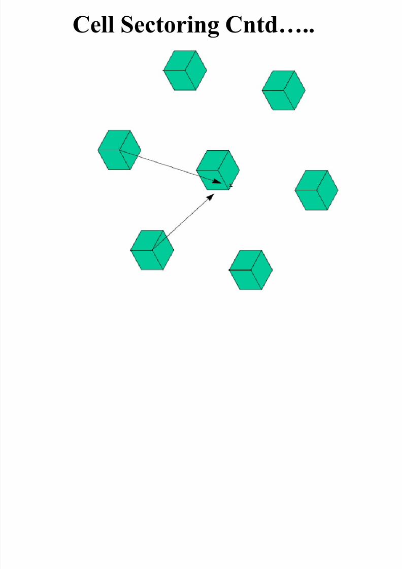
• When sectoring is employed, the channels
used in a particular cell are broken down into
sectored groups and are used only within
particular sector.
• Assuming seven-cell reuse, for the case of 120
degrees sectors.
• the number of interferers in the first tier is
reduced from six to two.
• How come ????
Cell Sectoring Cntd….
C ll S i C d
8/13/2019 Into to Communication Systems Chap 2
http://slidepdf.com/reader/full/into-to-communication-systems-chap-2 46/60
Cell Sectoring Cntd…..
C ll S i C d

8/13/2019 Into to Communication Systems Chap 2
http://slidepdf.com/reader/full/into-to-communication-systems-chap-2 47/60
•
The reduction in interference increases SIR• which allows us to reduce the cluster size.
• Hence capacity is increased.
For example:If N= 7 with 120 degree sectoring, the SIR
increases to 24.5 dB.
Can you Prove it ????
Cell Sectoring Cntd…..
8/13/2019 Into to Communication Systems Chap 2
http://slidepdf.com/reader/full/into-to-communication-systems-chap-2 48/60
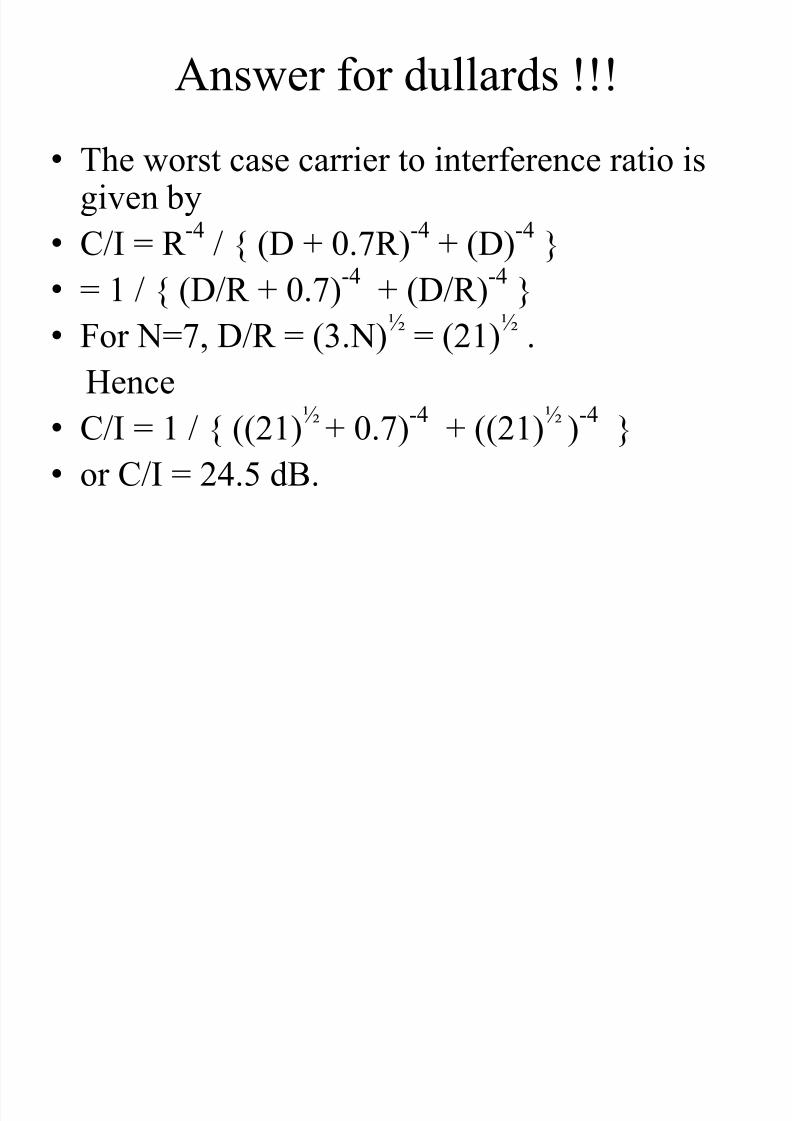
Answer for dullards !!!
• The worst case carrier to interference ratio isgiven by
• C/I = R -4
/ { (D + 0.7R)-4
+ (D)-4
}
• = 1 / { (D/R + 0.7)-4 + (D/R)-4 }• For N=7, D/R = (3.N)
½ = (21)
½ .
Hence
• C/I = 1 / { ((21)½ + 0.7)-4 + ((21)½ )-4 }• or C/I = 24.5 dB.

8/13/2019 Into to Communication Systems Chap 2
http://slidepdf.com/reader/full/into-to-communication-systems-chap-2 49/60
• So far we have shown that sectoring improves
SIR.
• Now if we prove that reducing cluster size
with sectoring can increase the capacity, our
job will be done.
•
But who wil l bell the cat ????
Cell Sectoring Cntd…..

8/13/2019 Into to Communication Systems Chap 2
http://slidepdf.com/reader/full/into-to-communication-systems-chap-2 50/60
Take Some pain Guyzzz !!!!
• Calculate C/I for the case of 120 degreessectoring with N=4
• Calculate C/I for 60 degrees sectoring with
N = 7• Last but not the least
• Measure C/I for N= 4 & N= 12 with 60
degrees sectoring• Give your overall comments about the
combination giving best results in terms ofcapacity & Interference.

8/13/2019 Into to Communication Systems Chap 2
http://slidepdf.com/reader/full/into-to-communication-systems-chap-2 51/60
Micro Cell Zone Concept
• Do you really believe cell sectoring is an
ultimate solution ???
• Do you think of any disadvantage it contains???

8/13/2019 Into to Communication Systems Chap 2
http://slidepdf.com/reader/full/into-to-communication-systems-chap-2 52/60
The two main disadvantages of sectoring are
1. It increases inter-cell handovers
2. The trunking eff iciency is decreased
Micro Cell Zone Concept covers both points
Micro Cell Zone Concept
Mi C ll Z C t

8/13/2019 Into to Communication Systems Chap 2
http://slidepdf.com/reader/full/into-to-communication-systems-chap-2 53/60
I n this scheme
Sectors are converted to zones.
mobile travels from one zone to zone to otherzone within the cell, it retains the same
channel.
Thus unlike in sectoring, a handoff is notrequired at the MSC.
In this way a given channel is active only inthe particular zone in which the mobile istraveling
Micro Cell Zone Concept
Mi C ll Z C t

8/13/2019 Into to Communication Systems Chap 2
http://slidepdf.com/reader/full/into-to-communication-systems-chap-2 54/60
while the cell maintains a particular coverage
radius , the co-channel interference in the cellular
system is reduced because
1. A large central base station is replaced byseveral lower powered transmitter on theedges of the of the cell.
2. Decrease co-channel interference improves
the signal quality and also leads to anincrease in capacity without the degradationin trucking eff iciency
Micro Cell Zone Concept
Mi C ll Z C t

8/13/2019 Into to Communication Systems Chap 2
http://slidepdf.com/reader/full/into-to-communication-systems-chap-2 55/60
Micro Cell Zone Concept

8/13/2019 Into to Communication Systems Chap 2
http://slidepdf.com/reader/full/into-to-communication-systems-chap-2 56/60
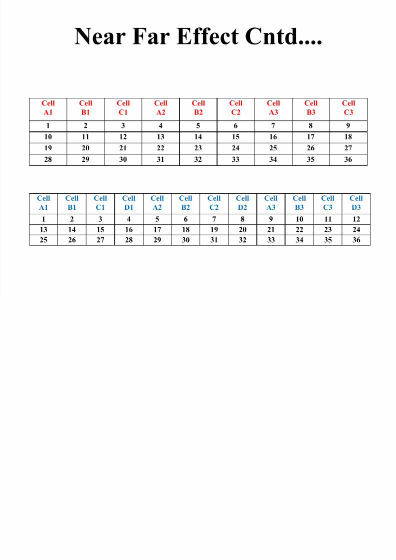
Near Far Effect
• As name suggests, it’s the effect of nearuser’s transmission on far user.
• If both using adjacent channels, the effect is pronounced.
• If near user’s power is more, the effect is
even more prominent.

8/13/2019 Into to Communication Systems Chap 2
http://slidepdf.com/reader/full/into-to-communication-systems-chap-2 57/60
The receiver will not be able to decode far
user mainly because
1. Filter are ideally not very sharp .2. Signal from far user deteriorates enough
when reaches BTS.
So what’s the solution ?????
Near Far Effect Cntd....

8/13/2019 Into to Communication Systems Chap 2
http://slidepdf.com/reader/full/into-to-communication-systems-chap-2 58/60
Two proposed solutions are
1. Deployment of POWER CONTROL .
2. Proper distribution of Channel frequencies(adjacent channels should be separated far
enough).
Near Far Effect Cntd....
Near Far Effect Cntd

8/13/2019 Into to Communication Systems Chap 2
http://slidepdf.com/reader/full/into-to-communication-systems-chap-2 59/60
Near Far Effect Cntd....
8/13/2019 Into to Communication Systems Chap 2
http://slidepdf.com/reader/full/into-to-communication-systems-chap-2 60/60
Cell
A1
Cell
B1
Cell
C1
Cell
D1
Cell
A2
Cell
B2
Cell
C2
Cell
D2
Cell
A3
Cell
B3
Cell
C3
Cell
D3
1 2 3 4 5 6 7 8 9 10 11 12
13 14 15 16 17 18 19 20 21 22 23 24
25 26 27 28 29 30 31 32 33 34 35 36
Cell
A1
Cell
B1
Cell
C1
Cell
A2
Cell
B2
Cell
C2
Cell
A3
Cell
B3
Cell
C3
1 2 3 4 5 6 7 8 9
10 11 12 13 14 15 16 17 18
19 20 21 22 23 24 25 26 27
28 29 30 31 32 33 34 35 36
Near Far Effect Cntd....


