8
Circuit Breaker LTB D 72.5 - 170 kV FSA spring operating mechanisms For single-pole operation
| Date post: | 16-Feb-2016 |
| Category: |
Documents |
| Upload: | razvan-mares |
| View: | 333 times |
| Download: | 20 times |

Circuit Breaker LTB D 72.5 - 170 kV FSA spring operating mechanisms
For single-pole operation

2
LTB D - proven design
LTB D circuit breakers with the ABB Auto- PufferTM interrupter and spring operating mechanisms have been reliably serving utilities around the world since 1991. Over 20,000 units have been delivered to over 120 countries with an excellent record of performance.
The LTB D is designed for system voltages 72.5 – 170 kV and rated for breaking current of 40 kA. LTB D is one member of the extensive and proven ABB SF6 circuit breaker family, which covers the voltage range from 72.5 up to 800 kV and for breaking capabilities up to 80 kA.
The LTB D for single pole operation has been optimized using the well proven FSA 1 spring operating mechanism in compliance with the major international standards including IEC and ANSI.
DesignThe three poles of the circuit breaker are mounted on a pole beam, supported by a two column frame. Each pole is equipped with its own spring operating mechanism of trip-free design, containing both closing and tripping springs. The operating mechanisms are mechanically identical. Operational controls are centralized in the centre mechanism and cabling between mechanisms is factory installed and tested prior to delivery. Minimum adjustment of the circuit breaker is required during site assembly.
The circuit breaker poles are identical sealed, single pressure, SF6 units, including breaking unit and hollow post insulators and mechanism housings. The poles are connected by factory installed SF6 gas piping connected to a central manifold block for site filling and SF6 density monitoring. ABB’s well proven double nitrile rubber static and dynamic seal designs ensure a maximum SF6 leak rate of less than 0.5% per year.
Simply reliable, fully functionalABB’s more than 100 years experience in the delivery of HV circuit breakers worldwide guarantees our customers can easily specify what they require and be assured of receiving their circuit breakers on time and to the high quality expected and guaranteed by ABB. The LTB D single-pole operated design can be specified by rated voltage, insulator type, phase distance, control voltage and pre-engineered flexible range of control functions.
Main features and advantages
•Lowenergy,arc-assistedAuto-puffer™ interrupter
•Highdielectricstrengthandelectricalendurancefromoptimized contact system design (IEC class C2)
•Proven nitrile rubber double sealing systems
•Available with porcelain (brown or grey) or silicone rubber composite insulators
•Trip-free, cam disc, spring operating mechanisms (IEC class M2)
•Vibration proof, multi-stage operating latches with low operating power
•High seismic withstand capability (0.5 g) due to opti-mized support design
•Mechanicallyconnectedcircuitbreakerpositionandspring charge status indicators
•Full functional module based controls design provid-ing ease of specification and security of delivery and performance
•Factory installed and tested cabling. No site cabling installation required between operating mechanisms
•Modular component design, allowing rigorous, staged and complete factory testing and minimum spare parts inventory
•Optimized packing and delivery arrangement to en-sure transport safety and simple, rapid installation
•Integrated Central Control Cubicle, CCC

3
Installation in less than one day
The functionally modular design, delivered fully tested from ABB allows the complete circuit breaker to be installed and ready for use within one day. Minimum adjustment of the circuit breaker is required during installation on site commissioning.
1. Delivery
2. Install support frames on foundation (30 minutes)
3. Bolt pole beam to support frames (30 minutes)
Foundation Foundation
Case 1: Welded support frame
Case 2: Circuit breaker poles Case 3: Operating mechanisms, mounted on pole beam with preterminated interphase cabling
Note! Installation times are indicative only and subject to work by suitably trained personnel with appropriate tools. All site works must be carried out in accordance with local laws, safety regulations and relevant ABB product information manual delivered with the circuit breaker.

4
Installation in less than one day
4. Install poles on pole beam (75 minutes)
5. Install substation cabling and HV connections (180 minutes)
6. SF6 gas filling (45 minutes) 7. Site commissioning tests (60 minutes)

5
Electrical controls — pre-engineered functional modules for operational securityAll interphase controls of the circuit breaker are completed in the ABB factory. No site cabling is required, ensuring fast and error free installation. All main circuit functions have been developed into pre-engineered modules that provide the user with simplicity of ordering and security of function. The standardized circuit and wiring design enables a high degree of automated quality control in the production of the circuit breaker.
Cabling is terminated using positive clip lock, vibration proof plug connections. All internal cabling is indelibly marked with unique cable numbers. Interphase cables have halogen free compound insulation, UV resistant sheaths and overlapped copper tape screens. Separate gland plate provided for substation cable entry. Well spaced, vertically mounted terminal blocks provided in central operating mechanism for connection of substation control and signalling cables.
Circuits Auxiliary contacts
SF6 density monitor
Two level: Refill/
Blocking
Spring limit
switch
Anti-pump relay
Control selector switch Local / Remote / Disconnected
Local operation selection Single-/
Three-pole operation
Trip / Close local switch
MCB Power outlet
earth fault MCB (RCD)
Close Standard Standard Standard Standard Standard Standard Standard
Trip 1 Standard Standard Standard Standard Standard
Trip 2 Standard Standard Standard Standard
Motor Standard Standard
Heater and auxiliaries70 W continuous 140 W thermostat controlled
Standard Optional
Signalling 7+7 1+1 1+1 1+1 1+1 Optional
Device description
- Rotary wiping action
- Double break
Normally closed
contacts.Temperature
compen-sated.
MPa abs.
Rotary, padlockable
RotaryRotary,
spring return
Standard Option
Control voltage 110 - 125 VDC 220 - 250 VDC
Motor voltage 110 - 125 VDC 220 - 250 VDC 220 VAC 120 VAC
Heater and auxiliary voltage 220 VAC 120 VAC
Additional options
Undervoltage relay
Pole discrepancy
Spring charge failure monitoring
Door switch activated internal lamp
Preparation for trip circuit supervision

6
Technical data according to IEC
GeneralCircuit breaker type LTB 72.5 D1/B 145 D1/B 170 D1/B
Type of operation 1-pole operation
Number of poles 3
Porcelain (brown-standard / grey - option) mm/kV 25 or 31
Composite silicone rubber (option) mm/kV 25
Operating temperature º C -30 to +40 (Lower or higher on request)
Seismic withstand 0.2 - 0.5 g
Ratings and guaranteed performance in accordance with IEC 62271-100Rated voltage kV 72.5 145 170
Rated insulation level
Lightning impulse withstand voltage
to earth kVpeak 325 650 750
across the open circuit-breaker kVpeak 325 650 750
Power frequency withstand voltage
to earth, dry kV 140 275 325
across the open circuit-breaker, dry kV 140 275 325
Rated frequency Hz 50/60
Rated normal current A 3150
Rated short-circuit breaking current kA 40
First-pole-to-clear factor 1.5
Rated short-circuit making current kApeak 100
Rated operating sequence O-0.3 s-CO-3 min-CO
Rated duration of short-circuit current (40 kA) s 3
Opening time ms 28-35
Break time ms ≤ 50
Closing time ms ≤ 70
Capacitive current switching Class C2
Mechanical endurance Class M2
Operating mechanismMotor operated spring closing mechanism Type FSA1
Degree of protection IP55
Power required at rated supply voltage by
Closing coil W 500
Opening coil W 500
Motor W 740
Heating elements, continuously W 70
Heating elements, connected by thermostat W 140
Number of spare auxiliary contacts Normally open 7
Number of spare auxiliary contacts Normally closed 7
Masses and dimensionsMass of breaker module excl. operating mechanism (porcelain / polymer insulators)
kg 3 x 300 / 3 x 130
Operating mechanism kg 177 + 142 x 2
7
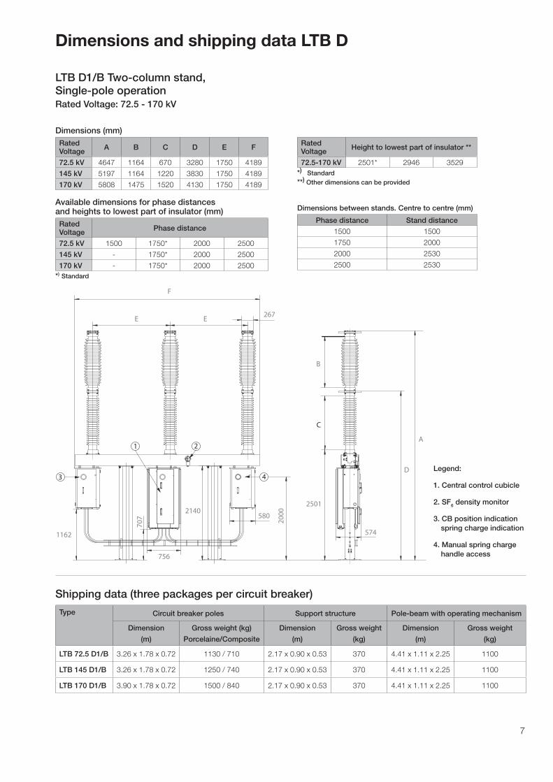
Dimensions and shipping data LTB D
LTB D1/B Two-column stand,Single-pole operationRated Voltage: 72.5 - 170 kV
Dimensions (mm) RatedVoltage A B C D E F
72.5 kV 4647 1164 670 3280 1750 4189
145 kV 5197 1164 1220 3830 1750 4189
170 kV 5808 1475 1520 4130 1750 4189
Available dimensions for phase distances and heights to lowest part of insulator (mm)RatedVoltage Phase distance
72.5 kV 1500 1750* 2000 2500
145 kV - 1750* 2000 2500
170 kV - 1750* 2000 2500*) Standard
F
EE
A
B
C
2501
574
5802140
756
267
1162
D
707
3
1 2
4
2000
RatedVoltage Height to lowest part of insulator **
72.5-170 kV 2501* 2946 3529*) Standard **) Other dimensions can be provided
Dimensions between stands. Centre to centre (mm)
Phase distance Stand distance
1500 1500
1750 2000
2000 2530
2500 2530
Type Circuit breaker poles Support structure Pole-beam with operating mechanism
Dimension
(m)
Gross weight (kg)
Porcelaine/Composite
Dimension
(m)
Gross weight
(kg)
Dimension
(m)
Gross weight
(kg)
LTB 72.5 D1/B 3.26 x 1.78 x 0.72 1130 / 710 2.17 x 0.90 x 0.53 370 4.41 x 1.11 x 2.25 1100
LTB 145 D1/B 3.26 x 1.78 x 0.72 1250 / 740 2.17 x 0.90 x 0.53 370 4.41 x 1.11 x 2.25 1100
LTB 170 D1/B 3.90 x 1.78 x 0.72 1500 / 840 2.17 x 0.90 x 0.53 370 4.41 x 1.11 x 2.25 1100
Shipping data (three packages per circuit breaker)
Legend:
1. Central control cubicle
2. SF6 density monitor
3. CB position indication spring charge indication
4. Manual spring charge handle access

ABB ABHigh Voltage Products
SE-771 80 LUDVIKA, SWEDENTel: +46 (0)240 78 20 00Fax: +46 (0)240 78 36 50E-mail: [email protected]: http://www.abb.com
©C
opyr
ight
200
7 A
BB
, All
right
rese
rved
. Pub
licat
ion
1HS
M 9
543
22-1
0en,
Circ
uit B
reak
er L
TB D
72.
5 -
170
kV w
ith s
prin
g op
erat
ing
mec
hani
sm F
SA
, Edi
tion
1, 2
007-
08. P
rint:
ww
w.h
enni
ngso
ns.s
e
NOTE! ABB AB is working continuously to improve the products. We therefore reserve the right to change designs, dimensions and data without prior notice.


