x86 Registers The main tools to write programs in x86 assembly are the processor registers. The registers are like variables built in the processor. Using registers instead of memory to store values makes the process faster and cleaner. The problem with the x86 serie of processors is that there are few registers to use. This section describes the main use of each register and ways to use them. That in note that the rules described here are more suggestions than strict rules. Some operations need absolutely some kind of registers but most of the you can use any of the freely. Here is a list of the available registers on the 386 and higher processors. This list shows the 32 bit registers. Most of the can be broken down to 16 or even 8 bits register. General registers EAX EBX ECX EDX Segment registers CS DS ES FS GS SS Index and pointers ESI EDI EBP EIP ESP Indicator EFLAGS General registers As the title says, general register are the one we use most of the time Most of the instructions perform on these registers. They all can be broken down into 16 and 8 bit registers. 32 bits : EAX EBX ECX EDX 16 bits : AX BX CX DX 8 bits : AH AL BH BL CH CL DH DL The "H" and "L" suffix on the 8 bit registers stand for high byte and low byte. With this out of the way, let's see their individual main use EAX,AX,AH,AL : Called the Accumulator register. It is used for I/O port access, arithmetic, interrupt calls, etc... EBX,BX,BH,BL : Called the Base register It is used as a base pointer for memory access Gets some interrupt return values
Transcript
x86 Registers
The main tools to write programs in x86 assembly are the processor registers.
The registers are like variables built in the processor. Using registers instead of
memory to store values makes the process faster and cleaner. The problem with
the x86 serie of processors is that there are few registers to use. This section
describes the main use of each register and ways to use them. That in note that
the rules described here are more suggestions than strict rules. Some operations
need absolutely some kind of registers but most of the you can use any of the
freely.
Here is a list of the available registers on the 386 and higher processors. This list
shows the 32 bit registers. Most of the can be broken down to 16 or even 8 bits
register.
General registers
EAX EBX ECX EDX
Segment registers
CS DS ES FS GS SS
Index and pointers
ESI EDI EBP EIP ESP
Indicator
EFLAGS
General registers
As the title says, general register are the one we use most of the time Most of the
instructions perform on these registers. They all can be broken down into 16 and
8 bit registers.
32 bits : EAX EBX ECX EDX
16 bits : AX BX CX DX
8 bits : AH AL BH BL CH CL DH DL
The "H" and "L" suffix on the 8 bit registers stand for high byte and low byte.
With this out of the way, let's see their individual main use
EAX,AX,AH,AL : Called the Accumulator register.
It is used for I/O port access, arithmetic, interrupt
calls,
etc...
EBX,BX,BH,BL : Called the Base register
It is used as a base pointer for memory access
Gets some interrupt return values
ECX,CX,CH,CL : Called the Counter register
It is used as a loop counter and for shifts
Gets some interrupt values
EDX,DX,DH,DL : Called the Data register
It is used for I/O port access, arithmetic, some interrupt
calls.
Segment registers
Segment registers hold the segment address of various items. They are only
available in 16 values. They can only be set by a general register or special
instructions. Some of them are critical for the good execution of the program and
you might want to consider playing with them when you'll be ready for multi-
segment programming
CS : Holds the Code segment in which your program runs.
Changing its value might make the computer hang.
DS : Holds the Data segment that your program accesses.
Changing its value might give erronous data.
ES,FS,GS : These are extra segment registers available for
far pointer addressing like video memory and such.
SS : Holds the Stack segment your program uses.
Sometimes has the same value as DS.
Changing its value can give unpredictable results,
mostly data related.
Indexes and pointers
Indexes and pointer and the offset part of and address. They have various uses
but each register has a specific function. They some time used with a segment
register to point to far address (in a 1Mb range). The register with an "E" prefix
can only be used in protected mode.
ES:EDI EDI DI : Destination index register
Used for string, memory array copying and setting and
for far pointer addressing with ES
DS:ESI EDI SI : Source index register
Used for string and memory array copying
SS:EBP EBP BP : Stack Base pointer register
Holds the base address of the stack
SS:ESP ESP SP : Stack pointer register
Holds the top address of the stack
CS:EIP EIP IP : Index Pointer
Holds the offset of the next instruction
It can only be read
The EFLAGS register
The EFLAGS register hold the state of the processor. It is modified by many
intructions and is used for comparing some parameters, conditional loops and
conditionnal jumps. Each bit holds the state of specific parameter of the last
instruction. Here is a listing :
Bit Label Desciption
---------------------------
0 CF Carry flag
2 PF Parity flag
4 AF Auxiliary carry flag
6 ZF Zero flag
7 SF Sign flag
8 TF Trap flag
9 IF Interrupt enable flag
10 DF Direction flag
11 OF Overflow flag
12-13 IOPL I/O Priviledge level
14 NT Nested task flag
16 RF Resume flag
17 VM Virtual 8086 mode flag
18 AC Alignment check flag (486+)
19 VIF Virutal interrupt flag
20 VIP Virtual interrupt pending flag
21 ID ID flag
Those that are not listed are reserved by Intel.
Undocumented registers
There are registers on the 80386 and higher processors that are not well
documented by Intel. These are divided in control registers, debug registers, test
registers and protected mode segmentation registers. As far as I know, the control
registers, along with the segmentation registers, are used in protected mode
programming, all of these registers are available on 80386 and higher processors
except the test registers that have been removed on the pentium. Control registers
are CR0 to CR4, Debug registers are DR0 to DR7, test registers are TR3 to TR7
and the protected mode segmentation registers are GDTR (Global Descriptor
This guide describes the basics of 32-bit x86 assembly language programming, covering a small but useful subset of the available instructions and assembler directives. There are several different assembly languages for generating x86 machine code. The one we will use in CS216 is the Microsoft Macro Assembler (MASM) assembler. MASM uses the standard Intel syntax for writing x86 assembly code.
The full x86 instruction set is large and complex (Intel's x86 instruction set manuals comprise over 2900 pages), and we do not cover it all in this guide. For example, there is a 16-bit subset of the x86 instruction set. Using the 16-bit programming model can be quite complex. It has a segmented memory model, more restrictions on register usage, and so on. In this guide, we will limit our attention to more modern aspects of x86 programming, and delve into the instruction set only in enough detail to get a basic feel for x86 programming.
Resources
Guide to Using Assembly in Visual Studio — a tutorial on building and debugging assembly code in Visual Studio
Intel x86 Instruction Set (Zack Smith) Intel's Pentium Manuals (the full gory details). Includes: Instruction
Set Reference (A-M), Instruction Set Reference (N-Z).
Registers
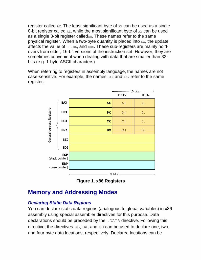
Modern (i.e 386 and beyond) x86 processors have eight 32-bit general purpose registers, as depicted in Figure 1. The register names are mostly historical. For example, EAX used to be called the accumulator since it was used by a number of arithmetic operations, and ECX was known as the counter since it was used to hold a loop index. Whereas most of the registers have lost their special purposes in the modern instruction set, by convention, two are reserved for special purposes — the stack pointer (ESP) and the base pointer (EBP).
For the EAX, EBX, ECX, and EDX registers, subsections may be used. For example, the least significant 2 bytes of EAX can be treated as a 16-bit
register called AX. The least significant byte of AX can be used as a single 8-bit register called AL, while the most significant byte of AX can be used as a single 8-bit register calledAH. These names refer to the same physical register. When a two-byte quantity is placed into DX, the update affects the value of DH, DL, and EDX. These sub-registers are mainly hold-overs from older, 16-bit versions of the instruction set. However, they are sometimes convenient when dealing with data that are smaller than 32-bits (e.g. 1-byte ASCII characters).
When referring to registers in assembly language, the names are not case-sensitive. For example, the names EAX and eax refer to the same register.
Figure 1. x86 Registers
Memory and Addressing Modes
Declaring Static Data Regions
You can declare static data regions (analogous to global variables) in x86
assembly using special assembler directives for this purpose. Data
declarations should be preceded by the .DATA directive. Following this
directive, the directives DB, DW, and DD can be used to declare one, two,
and four byte data locations, respectively. Declared locations can be
labeled with names for later reference — this is similar to declaring
variables by name, but abides by some lower level rules. For example,
locations declared in sequence will be located in memory next to one
another.
Example declarations:
.DATA
var DB 64 ; Declare a byte, referred to as location var, containing the value 64.
var2 DB ? ; Declare an uninitialized byte, referred to as location var2.
DB 10
; Declare a byte with no label, containing the value 10. Its location
is var2 + 1.
X DW ? ; Declare a 2-byte uninitialized value, referred to as location X.
Y DD 30000 ; Declare a 4-byte value, referred to as location Y, initialized to 30000.
Unlike in high level languages where arrays can have many dimensions and are accessed by indices, arrays in x86 assembly language are simply a number of cells located contiguously in memory. An array can be declared by just listing the values, as in the first example below. Two other common methods used for declaring arrays of data are
the DUP directive and the use of string literals. The DUP directive tells the
assembler to duplicate an expression a given number of times. For
example, 4 DUP(2) is equivalent to 2, 2, 2, 2.
Some examples:
Z DD 1, 2, 3 ; Declare three 4-byte values, initialized to 1, 2, and 3. The value of
location Z + 8 will be 3.
bytes DB 10 DUP(?) ; Declare 10 uninitialized bytes starting at location bytes.
arr DD 100
DUP(0) ; Declare 100 4-byte words starting at location arr, all initialized to
0
str DB 'hello',0 ; Declare 6 bytes starting at the address str, initialized to the ASCII
character values for hello and the null (0) byte.
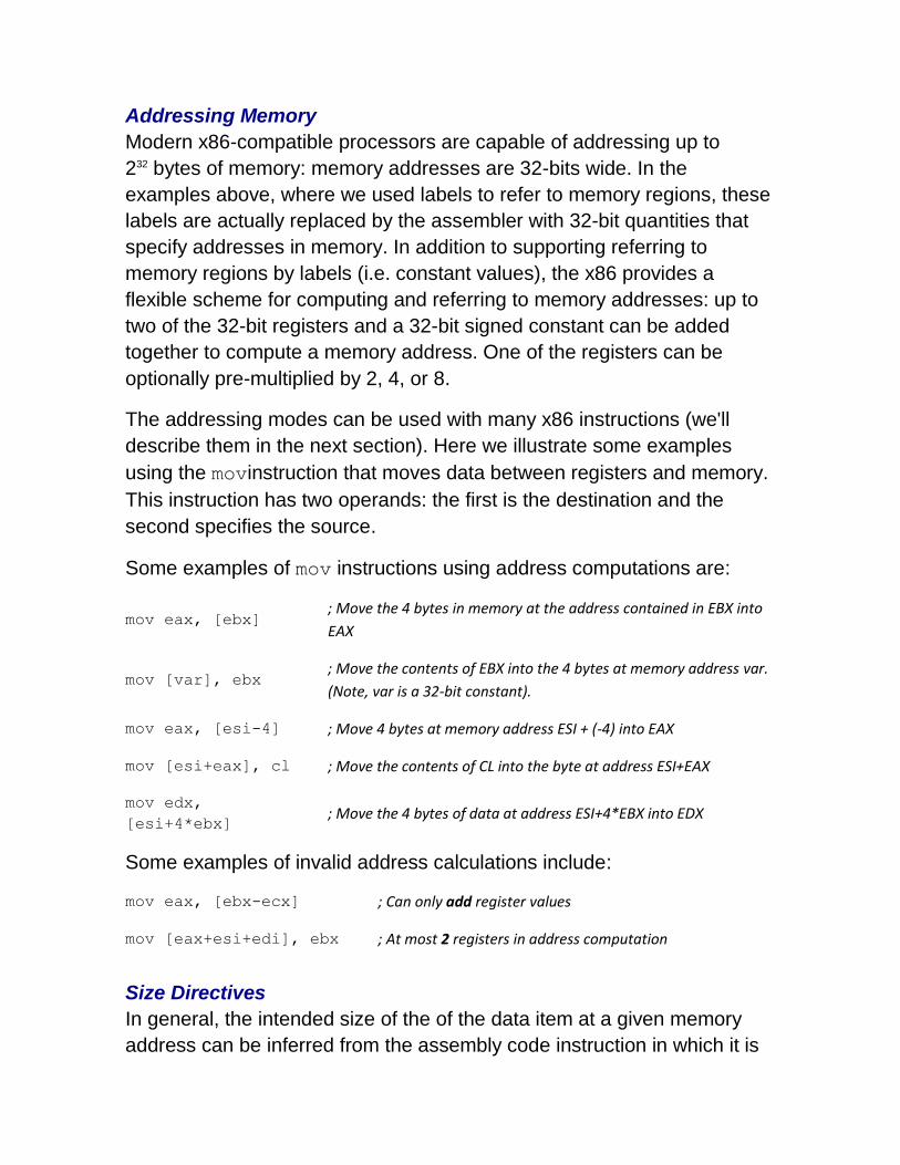
Addressing Memory
Modern x86-compatible processors are capable of addressing up to
232 bytes of memory: memory addresses are 32-bits wide. In the
examples above, where we used labels to refer to memory regions, these
labels are actually replaced by the assembler with 32-bit quantities that
specify addresses in memory. In addition to supporting referring to
memory regions by labels (i.e. constant values), the x86 provides a
flexible scheme for computing and referring to memory addresses: up to
two of the 32-bit registers and a 32-bit signed constant can be added
together to compute a memory address. One of the registers can be
optionally pre-multiplied by 2, 4, or 8.
The addressing modes can be used with many x86 instructions (we'll
describe them in the next section). Here we illustrate some examples
using the movinstruction that moves data between registers and memory.
This instruction has two operands: the first is the destination and the
second specifies the source.
Some examples of mov instructions using address computations are:
mov eax, [ebx] ; Move the 4 bytes in memory at the address contained in EBX into
EAX
mov [var], ebx ; Move the contents of EBX into the 4 bytes at memory address var.
(Note, var is a 32-bit constant).
mov eax, [esi-4] ; Move 4 bytes at memory address ESI + (-4) into EAX
mov [esi+eax], cl ; Move the contents of CL into the byte at address ESI+EAX
mov edx,
[esi+4*ebx] ; Move the 4 bytes of data at address ESI+4*EBX into EDX
Some examples of invalid address calculations include:
mov eax, [ebx-ecx] ; Can only add register values
mov [eax+esi+edi], ebx ; At most 2 registers in address computation
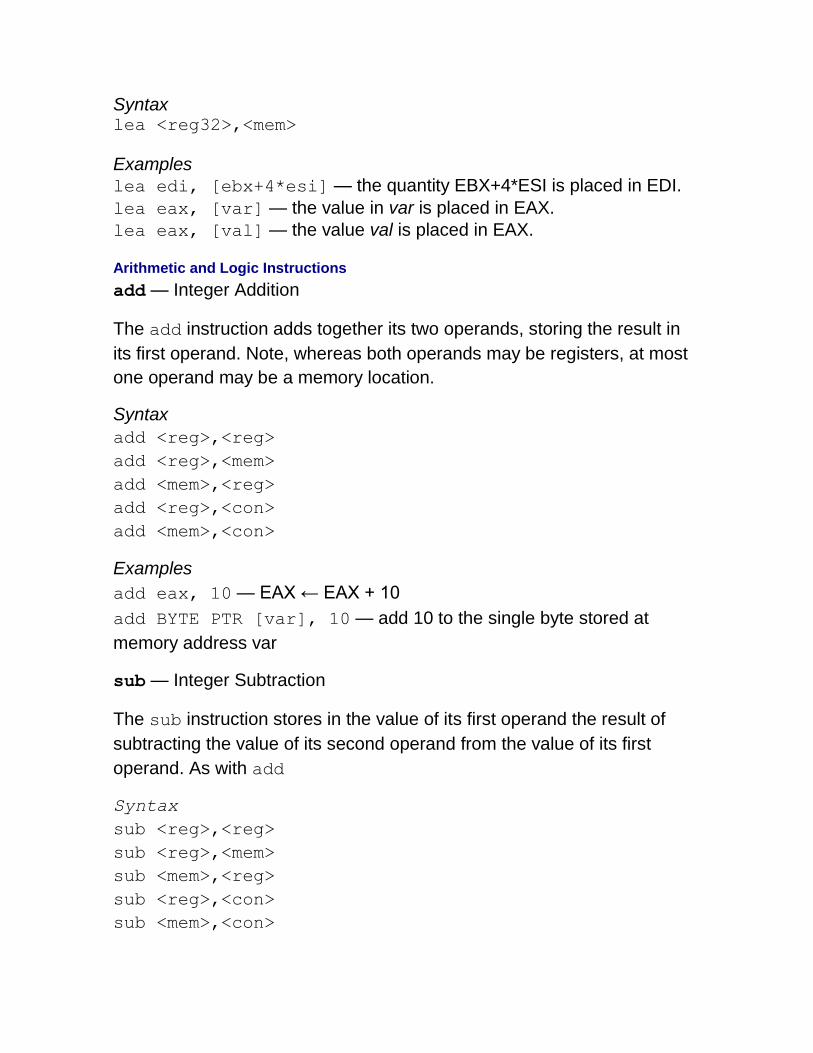
Size Directives
In general, the intended size of the of the data item at a given memory
address can be inferred from the assembly code instruction in which it is
referenced. For example, in all of the above instructions, the size of the
memory regions could be inferred from the size of the register operand.
When we were loading a 32-bit register, the assembler could infer that the
region of memory we were referring to was 4 bytes wide. When we were
storing the value of a one byte register to memory, the assembler could
infer that we wanted the address to refer to a single byte in memory.
However, in some cases the size of a referred-to memory region is
ambiguous. Consider the instruction mov [ebx], 2. Should this
instruction move the value 2 into the single byte at address EBX? Perhaps
it should move the 32-bit integer representation of 2 into the 4-bytes
starting at address EBX. Since either is a valid possible interpretation, the
assembler must be explicitly directed as to which is correct. The size
directives BYTE PTR, WORD PTR, and DWORD PTR serve this purpose,
indicating sizes of 1, 2, and 4 bytes respectively.
For example:
mov BYTE PTR [ebx],
2 ; Move 2 into the single byte at the address stored in EBX.
mov WORD PTR [ebx],
2 ; Move the 16-bit integer representation of 2 into the 2 bytes starting
at the address in EBX.
mov DWORD PTR [ebx],
2 ; Move the 32-bit integer representation of 2 into the 4 bytes starting
at the address in EBX.
Instructions
Machine instructions generally fall into three categories: data movement,
arithmetic/logic, and control-flow. In this section, we will look at important
examples of x86 instructions from each category. This section should not
be considered an exhaustive list of x86 instructions, but rather a useful
subset. For a complete list, see Intel's instruction set reference.
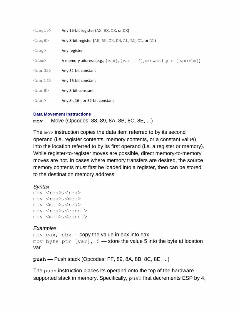
We use the following notation:
<reg32> Any 32-bit register (EAX, EBX, ECX, EDX, ESI, EDI, ESP, or EBP)
<reg16> Any 16-bit register (AX, BX, CX, or DX)
<reg8> Any 8-bit register (AH, BH, CH, DH, AL, BL, CL, or DL)
<reg> Any register
<mem> A memory address (e.g., [eax], [var + 4], or dword ptr [eax+ebx])
<con32> Any 32-bit constant
<con16> Any 16-bit constant
<con8> Any 8-bit constant
<con> Any 8-, 16-, or 32-bit constant
Data Movement Instructions
mov — Move (Opcodes: 88, 89, 8A, 8B, 8C, 8E, ...)
The mov instruction copies the data item referred to by its second
operand (i.e. register contents, memory contents, or a constant value)
into the location referred to by its first operand (i.e. a register or memory).
While register-to-register moves are possible, direct memory-to-memory
moves are not. In cases where memory transfers are desired, the source
memory contents must first be loaded into a register, then can be stored
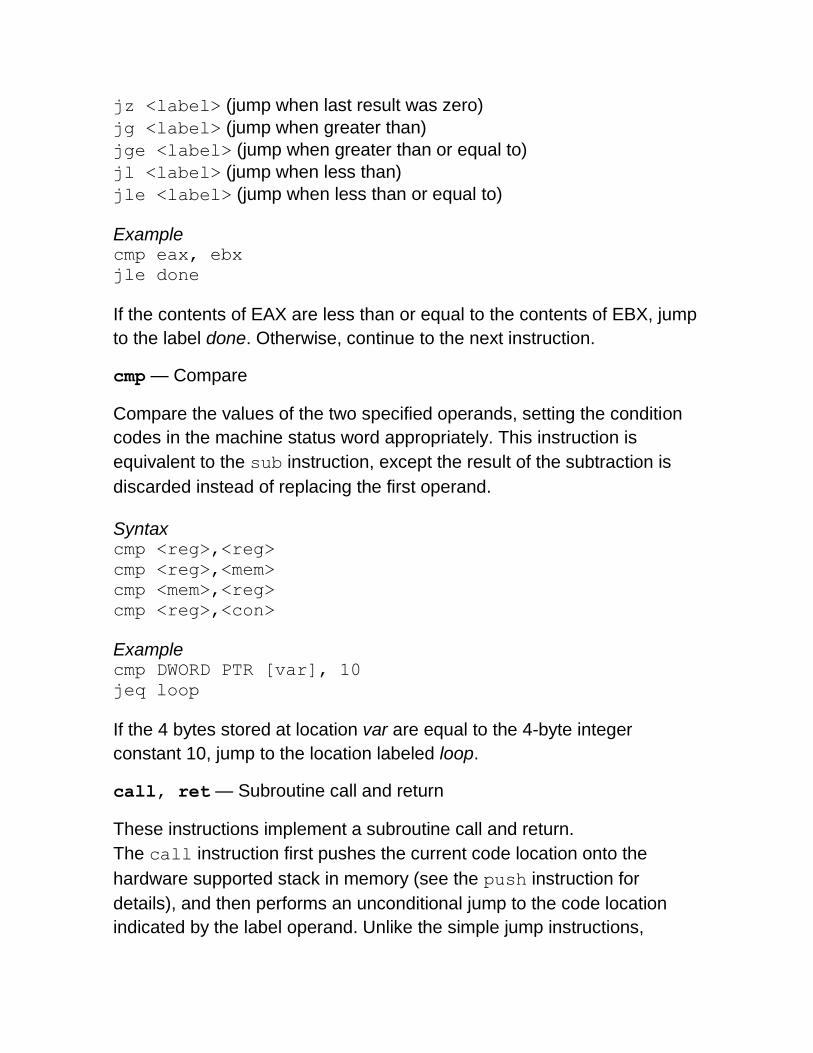
If the 4 bytes stored at location var are equal to the 4-byte integer
constant 10, jump to the location labeled loop.
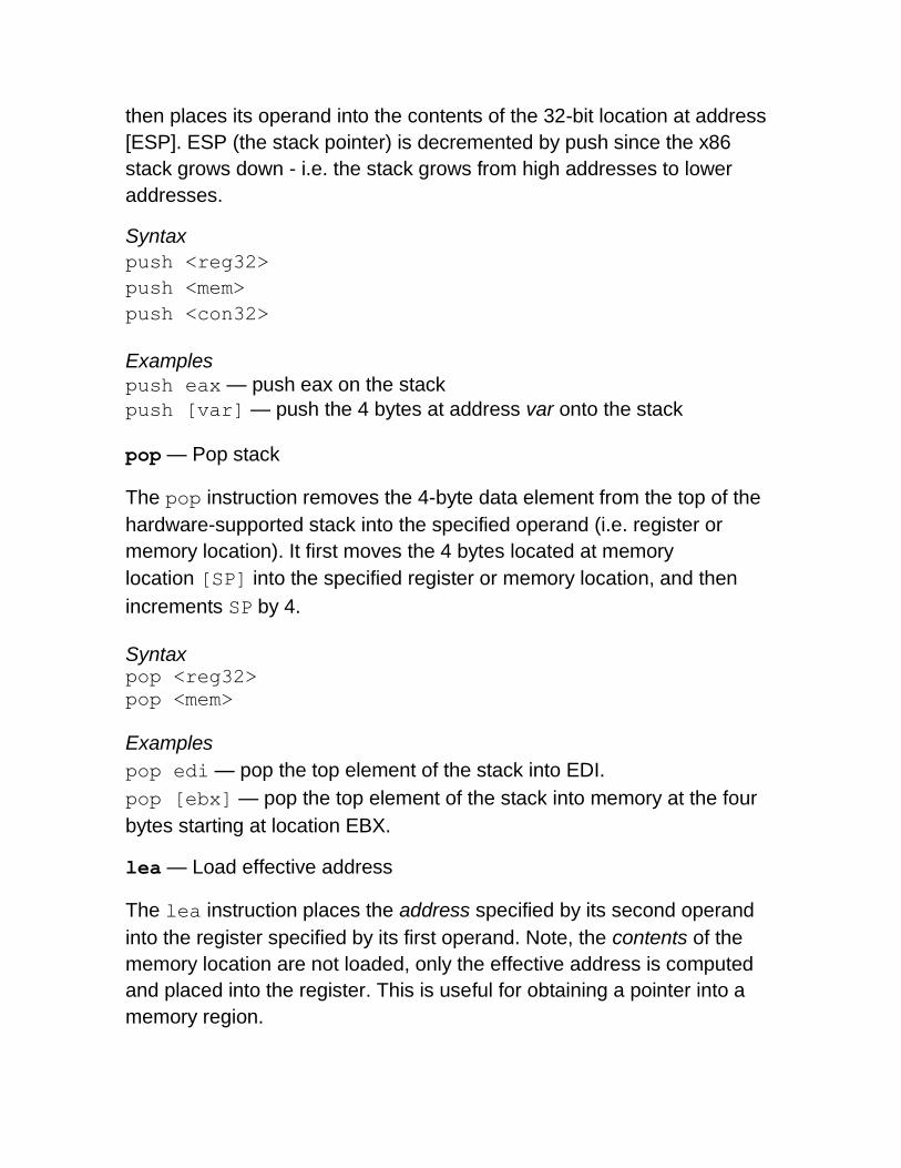
call, ret — Subroutine call and return
These instructions implement a subroutine call and return.
The call instruction first pushes the current code location onto the
hardware supported stack in memory (see the push instruction for
details), and then performs an unconditional jump to the code location
indicated by the label operand. Unlike the simple jump instructions,
the call instruction saves the location to return to when the subroutine
completes.
The ret instruction implements a subroutine return mechanism. This
instruction first pops a code location off the hardware supported in-
memory stack (see the pop instruction for details). It then performs an
unconditional jump to the retrieved code location.
Syntax call <label> ret
Calling Convention
To allow separate programmers to share code and develop libraries for
use by many programs, and to simplify the use of subroutines in general,
programmers typically adopt a common calling convention. The calling
convention is a protocol about how to call and return from routines. For
example, given a set of calling convention rules, a programmer need not
examine the definition of a subroutine to determine how parameters
should be passed to that subroutine. Furthermore, given a set of calling
convention rules, high-level language compilers can be made to follow
the rules, thus allowing hand-coded assembly language routines and
high-level language routines to call one another.
In practice, many calling conventions are possible. We will use the widely
used C language calling convention. Following this convention will allow
you to write assembly language subroutines that are safely callable from
C (and C++) code, and will also enable you to call C library functions from
your assembly language code.
The C calling convention is based heavily on the use of the hardware-
supported stack. It is based on the push, pop, call,
and ret instructions. Subroutine parameters are passed on the stack.
Registers are saved on the stack, and local variables used by subroutines
are placed in memory on the stack. The vast majority of high-level
procedural languages implemented on most processors have used similar
calling conventions.
The calling convention is broken into two sets of rules. The first set of
rules is employed by the caller of the subroutine, and the second set of
rules is observed by the writer of the subroutine (the callee). It should be
emphasized that mistakes in the observance of these rules quickly result
in fatal program errors since the stack will be left in an inconsistent state;
thus meticulous care should be used when implementing the call
convention in your own subroutines.
>
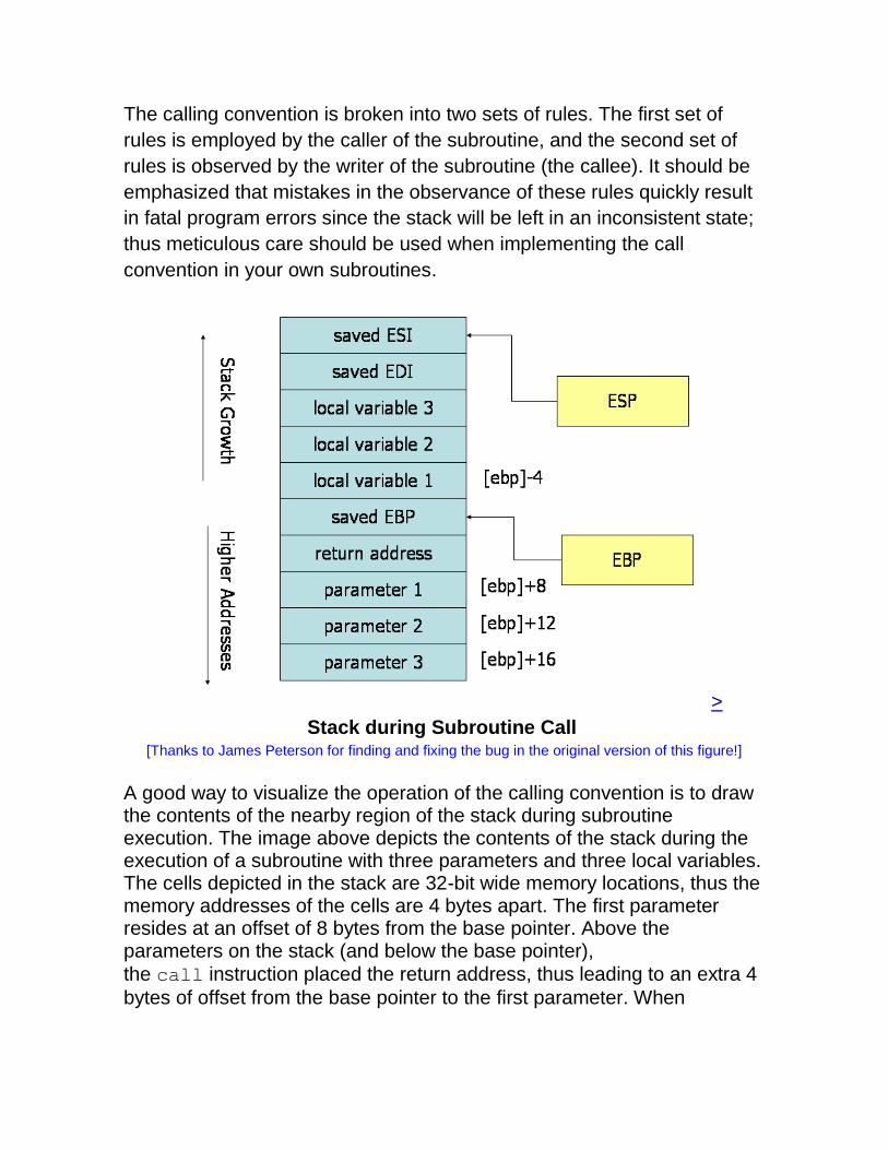
Stack during Subroutine Call [Thanks to James Peterson for finding and fixing the bug in the original version of this figure!]
A good way to visualize the operation of the calling convention is to draw the contents of the nearby region of the stack during subroutine execution. The image above depicts the contents of the stack during the execution of a subroutine with three parameters and three local variables. The cells depicted in the stack are 32-bit wide memory locations, thus the memory addresses of the cells are 4 bytes apart. The first parameter resides at an offset of 8 bytes from the base pointer. Above the parameters on the stack (and below the base pointer),
the call instruction placed the return address, thus leading to an extra 4
bytes of offset from the base pointer to the first parameter. When
the ret instruction is used to return from the subroutine, it will jump to the
return address stored on the stack.
Caller Rules
To make a subrouting call, the caller should:
1. Before calling a subroutine, the caller should save the contents of certain registers that are designated caller-saved. The caller-saved registers are EAX, ECX, EDX. Since the called subroutine is allowed to modify these registers, if the caller relies on their values after the subroutine returns, the caller must push the values in these registers onto the stack (so they can be restore after the subroutine returns.
2. To pass parameters to the subroutine, push them onto the stack before the call. The parameters should be pushed in inverted order (i.e. last parameter first). Since the stack grows down, the first parameter will be stored at the lowest address (this inversion of parameters was historically used to allow functions to be passed a variable number of parameters).
3. To call the subroutine, use the call instruction. This instruction
places the return address on top of the parameters on the stack, and branches to the subroutine code. This invokes the subroutine, which should follow the callee rules below.
After the subroutine returns (immediately following the call instruction),
the caller can expect to find the return value of the subroutine in the
register EAX. To restore the machine state, the caller should:
1. Remove the parameters from stack. This restores the stack to its state before the call was performed.
2. Restore the contents of caller-saved registers (EAX, ECX, EDX) by popping them off of the stack. The caller can assume that no other registers were modified by the subroutine.
Example
The code below shows a function call that follows the caller rules. The
caller is calling a function _myFunc that takes three integer parameters.
First parameter is in EAX, the second parameter is the constant 216; the
third parameter is in memory location var. push [var] ; Push last parameter first
push 216 ; Push the second parameter
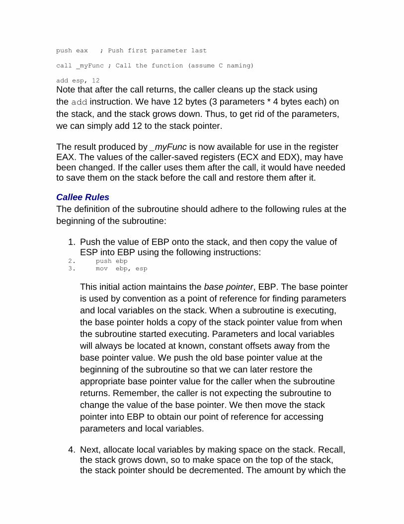
push eax ; Push first parameter last
call _myFunc ; Call the function (assume C naming)
add esp, 12
Note that after the call returns, the caller cleans up the stack using
the add instruction. We have 12 bytes (3 parameters * 4 bytes each) on
the stack, and the stack grows down. Thus, to get rid of the parameters,
we can simply add 12 to the stack pointer.
The result produced by _myFunc is now available for use in the register EAX. The values of the caller-saved registers (ECX and EDX), may have been changed. If the caller uses them after the call, it would have needed to save them on the stack before the call and restore them after it.
Callee Rules
The definition of the subroutine should adhere to the following rules at the
beginning of the subroutine:
1. Push the value of EBP onto the stack, and then copy the value of ESP into EBP using the following instructions:
2. push ebp 3. mov ebp, esp
This initial action maintains the base pointer, EBP. The base pointer
is used by convention as a point of reference for finding parameters
and local variables on the stack. When a subroutine is executing,
the base pointer holds a copy of the stack pointer value from when
the subroutine started executing. Parameters and local variables
will always be located at known, constant offsets away from the
base pointer value. We push the old base pointer value at the
beginning of the subroutine so that we can later restore the
appropriate base pointer value for the caller when the subroutine
returns. Remember, the caller is not expecting the subroutine to
change the value of the base pointer. We then move the stack
pointer into EBP to obtain our point of reference for accessing
parameters and local variables.
4. Next, allocate local variables by making space on the stack. Recall, the stack grows down, so to make space on the top of the stack, the stack pointer should be decremented. The amount by which the
stack pointer is decremented depends on the number and size of local variables needed. For example, if 3 local integers (4 bytes each) were required, the stack pointer would need to be decremented by 12 to make space for these local variables
(i.e., sub esp, 12). As with parameters, local variables will be
located at known offsets from the base pointer. 5. Next, save the values of the callee-saved registers that will be used
by the function. To save registers, push them onto the stack. The callee-saved registers are EBX, EDI, and ESI (ESP and EBP will also be preserved by the calling convention, but need not be pushed on the stack during this step).
After these three actions are performed, the body of the subroutine may
proceed. When the subroutine is returns, it must follow these steps:
1. Leave the return value in EAX. 2. Restore the old values of any callee-saved registers (EDI and ESI)
that were modified. The register contents are restored by popping them from the stack. The registers should be popped in the inverse order that they were pushed.
3. Deallocate local variables. The obvious way to do this might be to add the appropriate value to the stack pointer (since the space was allocated by subtracting the needed amount from the stack pointer). In practice, a less error-prone way to deallocate the variables is to move the value in the base pointer into the stack
pointer: mov esp, ebp. This works because the base pointer
always contains the value that the stack pointer contained immediately prior to the allocation of the local variables.
4. Immediately before returning, restore the caller's base pointer value by popping EBP off the stack. Recall that the first thing we did on entry to the subroutine was to push the base pointer to save its old value.
5. Finally, return to the caller by executing a ret instruction. This
instruction will find and remove the appropriate return address from the stack.
Note that the callee's rules fall cleanly into two halves that are basically
mirror images of one another. The first half of the rules apply to the
beginning of the function, and are commonly said to define
the prologue to the function. The latter half of the rules apply to the end of
the function, and are thus commonly said to define the epilogue of the
function.
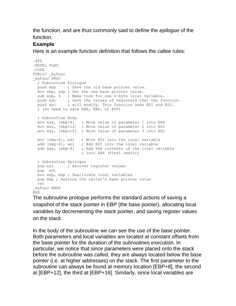
Example
Here is an example function definition that follows the callee rules:
.486
.MODEL FLAT
.CODE
PUBLIC _myFunc
_myFunc PROC
; Subroutine Prologue
push ebp ; Save the old base pointer value.
mov ebp, esp ; Set the new base pointer value.
sub esp, 4 ; Make room for one 4-byte local variable.
push edi ; Save the values of registers that the function
push esi ; will modify. This function uses EDI and ESI.
; (no need to save EBX, EBP, or ESP)
; Subroutine Body
mov eax, [ebp+8] ; Move value of parameter 1 into EAX
mov esi, [ebp+12] ; Move value of parameter 2 into ESI
mov edi, [ebp+16] ; Move value of parameter 3 into EDI
mov [ebp-4], edi ; Move EDI into the local variable
add [ebp-4], esi ; Add ESI into the local variable
add eax, [ebp-4] ; Add the contents of the local variable
; into EAX (final result)
; Subroutine Epilogue
pop esi ; Recover register values
pop edi
mov esp, ebp ; Deallocate local variables
pop ebp ; Restore the caller's base pointer value
ret
_myFunc ENDP
END
The subroutine prologue performs the standard actions of saving a
snapshot of the stack pointer in EBP (the base pointer), allocating local
variables by decrementing the stack pointer, and saving register values
on the stack.
In the body of the subroutine we can see the use of the base pointer. Both parameters and local variables are located at constant offsets from the base pointer for the duration of the subroutines execution. In particular, we notice that since parameters were placed onto the stack before the subroutine was called, they are always located below the base pointer (i.e. at higher addresses) on the stack. The first parameter to the subroutine can always be found at memory location [EBP+8], the second at [EBP+12], the third at [EBP+16]. Similarly, since local variables are
allocated after the base pointer is set, they always reside above the base pointer (i.e. at lower addresses) on the stack. In particular, the first local variable is always located at [EBP-4], the second at [EBP-8], and so on. This conventional use of the base pointer allows us to quickly identify the use of local variables and parameters within a function body.
The function epilogue is basically a mirror image of the function prologue.
The caller's register values are recovered from the stack, the local
variables are deallocated by resetting the stack pointer, the caller's base
pointer value is recovered, and the ret instruction is used to return to the