1 INTRODUCTION This document gives a detailed summary of the new features and modifications of FEM-Design version 12.0. We hope you will enjoy using the program and its new tools and possibilities. We wish you success. Strusoft, the developers Legend Pay attention / Note Useful hint Example Clicking left mouse button Clicking right mouse button Clicking middle mouse button Text Italic words marked in cyan are linked to their definition.
Transcript
1
INTRODUCTION This document gives a detailed summary of the new features and modifications of FEM-Design version 12.0. We hope you will enjoy using the program and its new tools and possibilities. We wish you success. Strusoft, the developers Legend
Pay attention / Note
Useful hint
Example
Clicking left mouse button
Clicking right mouse button
Clicking middle mouse button
Text Italic words marked in cyan are linked to their definition.
2
Table of contents
1. FOUNDATION ...................................................................................................................... 4
7. MODEL IMPORTING / EXPORTING ...................................................................................... 22
3
WHAT’S NEW IN FEM-DESIGN 12.0 - Foundation and soil modeling objects
- Foundation design
- Shear capacity in analysis result
- Rigidity type
- Renewed non-linear connections and supports
- Importing and exporting models in special Strusoft XML (struxml) format between
FD and other engineering softwares like Revit and Tekla
- New dead load case types
- RC Design “Configuration” function
- “Investigate” command in “Warnings” dialog
- Maximum number of load cases, load combinations and eigenfreqencies increased
4
1. FOUNDATION In FEM-Design 12.0 there are new objects to model the soil and foundation underneath the structure. These
objects are the soil, borehole, isolated foundation, wall foundation and foundation slab. These objects are only available in 3D Structure module.
1.1 Soil
Soil’s ground level, foundation level, water level, and strata top level can be different in each boreholes belonging to the soil. Boreholes are created in the corners of the soil region by default, but the user can create more if necessary (see 1.2). Soil’s limit depth is constant.
The soil details can be set in Default Settings:
5
The soil material details can be set individually:
User can choose if the user wishes to calculate soil as solid elements in analysis or just wants to consider it in foundation design calculation. In the Settings/Calculation/Code, Configuration dialog this option can be set.
The soil can be loaded only with Point load, Line load, Surface load (not with moments).
Concentrated mass cannot be defined in the soil.
6
1.2 Borehole
Ground level, foundation level, water level and the strata top level can be defined individually for each borehole. The details can be defined in Default Settings:
After selecting all boreholes and setting the properties as shown above, the following will appears:
Boreholes can be placed in arbitrary position in the soil.
With boreholes the user can define inclined level strata by setting the strata levels.
7
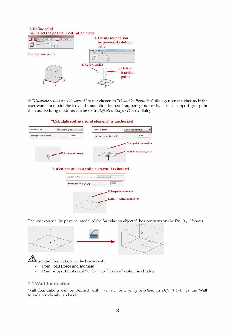
1.3 Isolated foundation
There are two ways to define an isolated foundation either by regular shape or shape by selection. If the user chooses the first definition mode, the regular shapes are rectangular, circular, polygonal, pick line or select region. For each regular shape, the user has to define the thickness and the position.
If the user chooses the second definition mode, the isolated foundation can be modelled with previously defined solids.
8
If “Calculate soil as a solid element” is not chosen in “Code, Configuration” dialog, user can choose, if the user wants to model the isolated foundation by point support group or by surface support group. In this case bedding modulus can be set in Default settings / General dialog.
The user can see the physical model of the foundation object if the user turns on the Display thickness.
Isolated foundation can be loaded with: - Point load (force and moment) - Point support motion, if “Calculate soil as solid” option unchecked
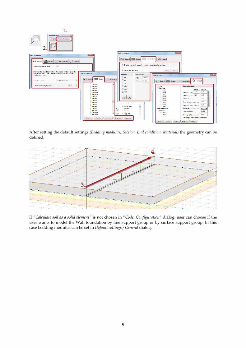
1.4 Wall foundation
Wall foundations can be defined with line, arc, or Line by selection. In Default Settings the Wall foundation details can be set.
9
After setting the default settings (Bedding modulus, Section, End condition, Material) the geometry can be defined.
If “Calculate soil as a solid element” is not chosen in “Code, Configuration” dialog, user can choose if the user wants to model the Wall foundation by line support group or by surface support group. In this case bedding modulus can be set in Default settings / General dialog.
10
If wall foundations’ surface support groups or surface – surface connections overlap each other (e.g. connected walls) the user has to correct this problem in the following way:
Wall foundation can be loaded with: - Point load (force and moment) - Line load (force and moment) - Line temperature variation load - Line stress load - Line support motion, if “Calculate soil as solid” option unchecked
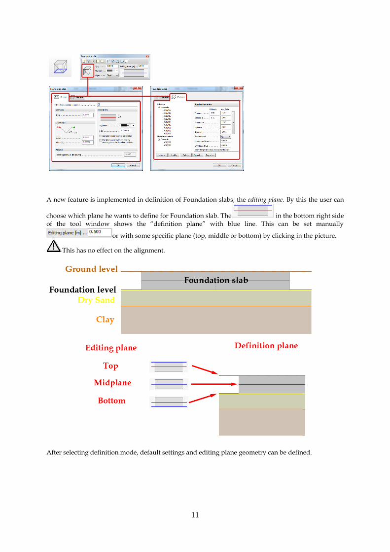
1.5 Foundation slab
Foundation slab can be defined with rectangular, circular, polygonal shapes, or by Pick line or Pick existing region. In Default Settings the Foundation slab details can be set.
11
A new feature is implemented in definition of Foundation slabs, the editing plane. By this the user can
choose which plane he wants to define for Foundation slab. The in the bottom right side of the tool window shows the “definition plane” with blue line. This can be set manually
or with some specific plane (top, middle or bottom) by clicking in the picture.
This has no effect on the alignment.
After selecting definition mode, default settings and editing plane geometry can be defined.
12
Foundation slab can be loaded with: - Point load (force and moment) - Line load (force and moment) - Surface load - Surface temperature variation load - Surface stress load - Surface support motion, if “Calculate soil as solid” option unchecked
1.6 Foundation design
In Configuration dialog, the user can set design options, like Design Approach, soil’s Safety Factors, the load combination’s Limit state and Settlements parameters.
In Foundation design only Check is available, Manual design or Auto design not. In Design approach tab, the user can select the design approach which influences the combination of effects. For more details, see Eurocode 1997-1:2006 Chapter 2.4.7.3.4.
13
In Safety factor tab, the user can set the safety factors of soil properties, resistance and permanent actions. In the Load combination tab, the user can set the limit states for each load combinations according to the selected Design approach. In the Settlements tab, the user can define the limit values of the relative displacements and rotations. For more details, see Eurocode 1997 H Annex.
By Design calculation parameter command the foundation’s calculation parameters can be set: 1. Isolated foundation:
o settlement limit value o preparation method (Cast in-situ or Precast)
2. Wall foundation:
o settlement limit value o maximum distance of calculated sections
3. Foundation slab
o settlement limit value
14
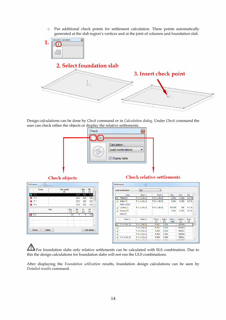
o Put additional check points for settlement calculation. These points automatically generated at the slab region’s vertices and at the joint of columns and foundation slab.
Design calculations can be done by Check command or in Calculation dialog. Under Check command the user can check either the objects or display the relative settlements.
For foundation slabs only relative settlements can be calculated with SLS combination. Due to this the design calculations for foundation slabs will not run the ULS combinations. After displaying the Foundation utilization results, foundation design calculations can be seen by Detailed results command.
15
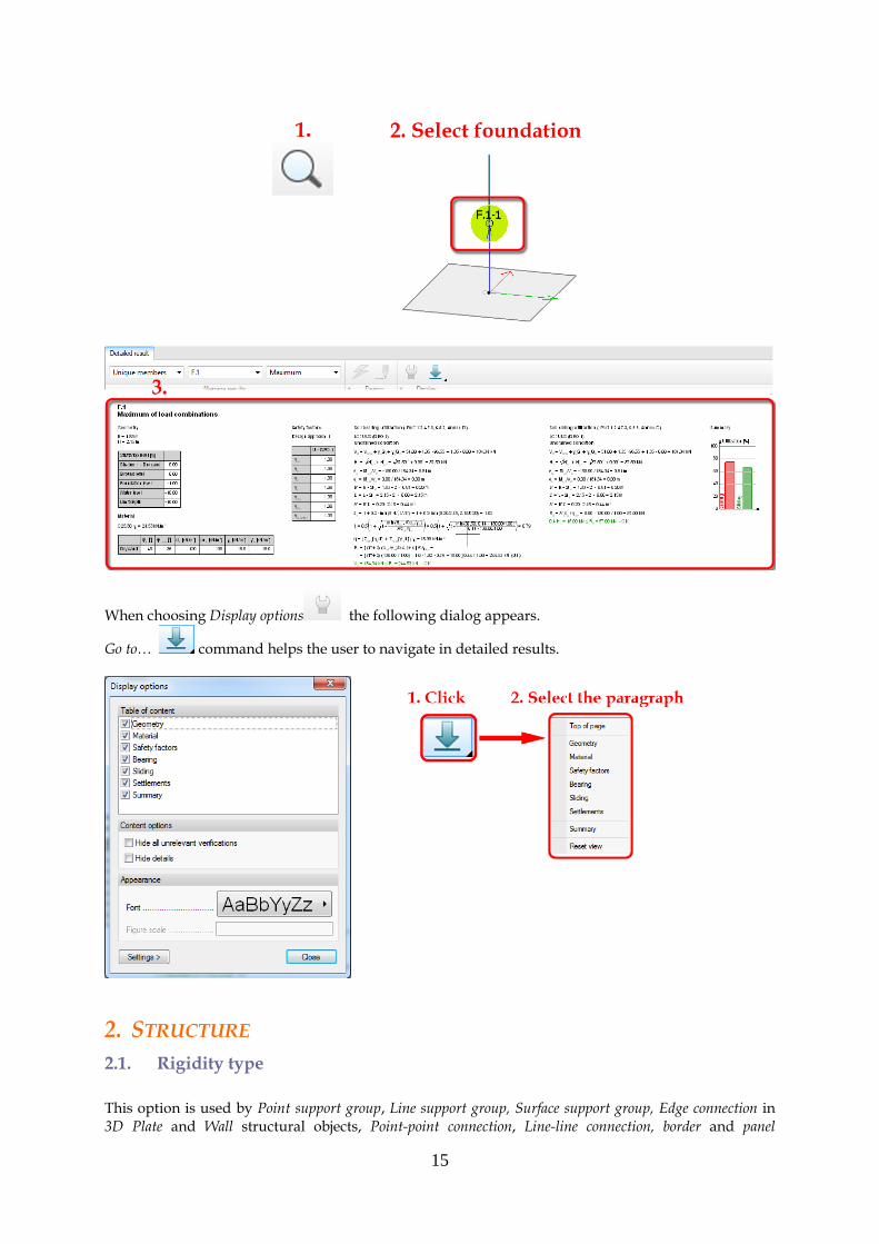
When choosing Display options the following dialog appears.
Go to… command helps the user to navigate in detailed results.
2. STRUCTURE
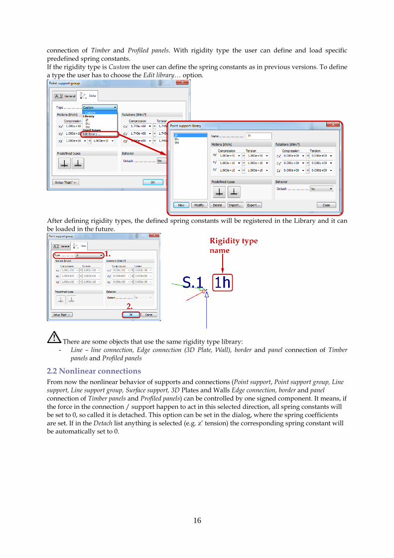
2.1. Rigidity type
This option is used by Point support group, Line support group, Surface support group, Edge connection in 3D Plate and Wall structural objects, Point-point connection, Line-line connection, border and panel
16
connection of Timber and Profiled panels. With rigidity type the user can define and load specific predefined spring constants. If the rigidity type is Custom the user can define the spring constants as in previous versions. To define a type the user has to choose the Edit library… option.
After defining rigidity types, the defined spring constants will be registered in the Library and it can be loaded in the future.
There are some objects that use the same rigidity type library: - Line – line connection, Edge connection (3D Plate, Wall), border and panel connection of Timber
panels and Profiled panels
2.2 Nonlinear connections
From now the nonlinear behavior of supports and connections (Point support, Point support group, Line support, Line support group, Surface support, 3D Plates and Walls Edge connection, border and panel connection of Timber panels and Profiled panels) can be controlled by one signed component. It means, if the force in the connection / support happen to act in this selected direction, all spring constants will be set to 0, so called it is detached. This option can be set in the dialog, where the spring coefficients are set. If in the Detach list anything is selected (e.g. z’ tension) the corresponding spring constant will be automatically set to 0.
17
If in Calculations dialog the ”Consider non-linear behavior of supports, trusses and connections” option is checked the calculation method is the following: If in the connection where the detach behavior is defined (e.g. z’ tension) the connection force is tension in the given direction (z’) in an iteration step all of the other spring constant will be set to 0. If in any later iteration step the connection force will be compression, the spring constants will be set to the previously defined values.
There is a big difference between setting any of the components to zero or selecting a detach behavior. If the user sets manually a component to zero, in the analysis the connection or support will not have rigidity in that direction.
3. LOADS
3.1. Dead load case types
The “+Dead load” is separated into two types of load cases, “+Structural dead load” and “+Soil dead load”. If the user defines a “+Structural dead load” case, FD calculates automatically the structural elements’ dead load. To consider only the soil’s dead load, the user has to define “+Soil dead load” case.
18
In order to calculate soil stresses it is recommended to put in the Ultimate Limit State load combination “+Soil dead load” and “+Structural dead load” cases; if the user wants to calculate settlements and displacements, only the “+Structural dead load“ should be put in the Serviceability Limit State combination.
4. FINITE ELEMENT
4.1. Solid element
Modeling soil can be done with 2 types of solid elements, see the picture below.
The user can choose which type of element the user wants to use for the analysis in Calculations dialog.
The calculation time increases significantly by using fine elements.
19
4.2. Shell element
In order to have the compatibility with solid elements, FD calculates with 9 node shell element in case of fine elements.
5. ANALYSIS
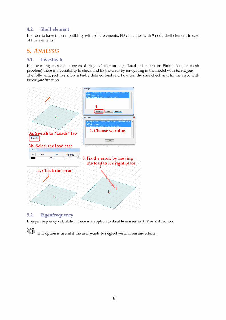
5.1. Investigate
If a warning message appears during calculation (e.g. Load mismatch or Finite element mesh problem) there is a possibility to check and fix the error by navigating in the model with Investigate. The following pictures show a badly defined load and how can the user check and fix the error with Investigate function.
5.2. Eigenfrequency
In eigenfrequency calculation there is an option to disable masses in X, Y or Z direction.
This option is useful if the user wants to neglect vertical seismic effects.
20
5.3. Maximum number of calculations
The maximum number of load cases, load combinations, buckling shapes and eigenfrequencies FD can calculate are 200 instead of 100.
5.4. Iteration number
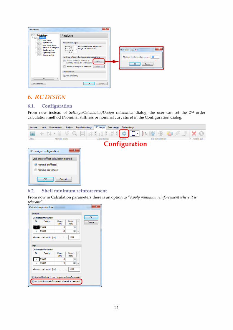
There is a possibility for the user to set the maximum iteration number of nonlinear calculation in Calculation dialog.
21
6. RC DESIGN
6.1. Configuration
From now instead of Settings/Calculation/Design calculation dialog, the user can set the 2nd order calculation method (Nominal stiffness or nominal curvature) in the Configuration dialog.
6.2. Shell minimum reinforcement
From now in Calculation parameters there is an option to “Apply minimum reinforcement where it is relevant”.
22
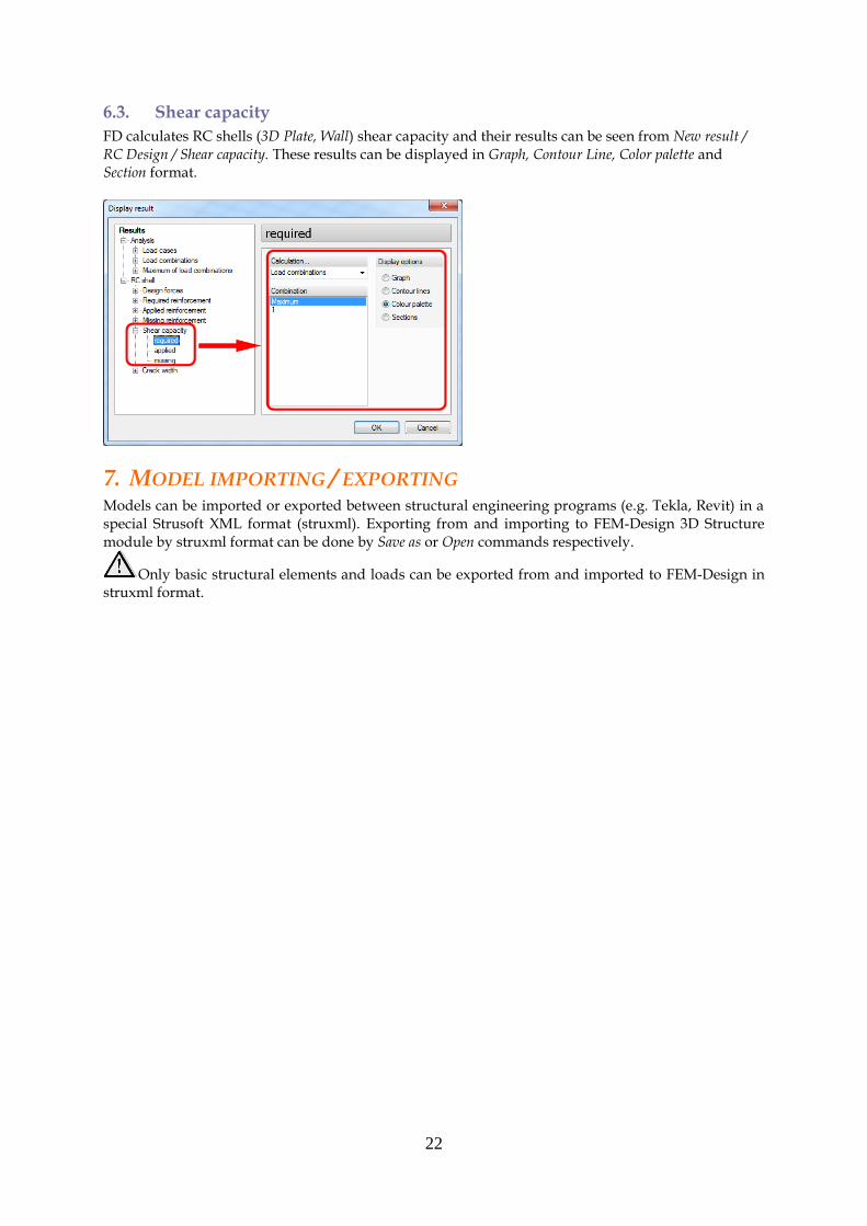
6.3. Shear capacity
FD calculates RC shells (3D Plate, Wall) shear capacity and their results can be seen from New result / RC Design / Shear capacity. These results can be displayed in Graph, Contour Line, Color palette and Section format.
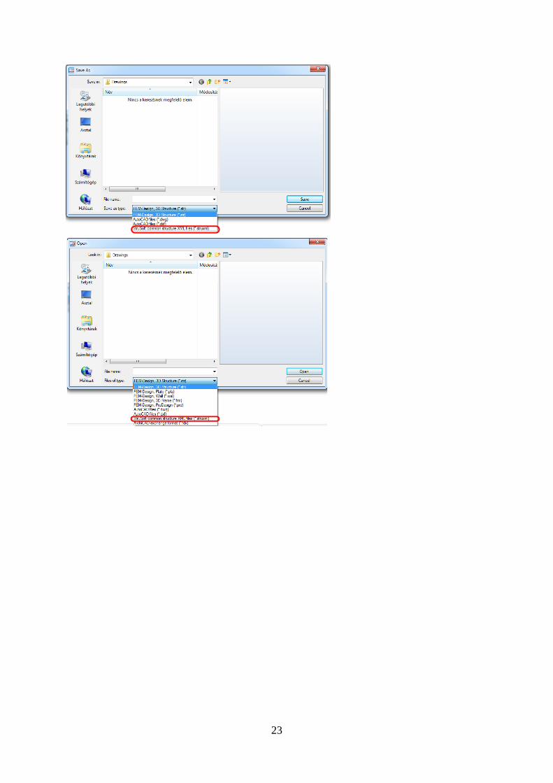
7. MODEL IMPORTING / EXPORTING Models can be imported or exported between structural engineering programs (e.g. Tekla, Revit) in a special Strusoft XML format (struxml). Exporting from and importing to FEM-Design 3D Structure module by struxml format can be done by Save as or Open commands respectively.
Only basic structural elements and loads can be exported from and imported to FEM-Design in struxml format.