6. Serviceability 6. Serviceability 6. Serviceability 6. Serviceability INTRODUCTION INTRODUCTION CRACKING IN FLEXURAL MEMBERS REVISED KCI CODE PROVISIONS (2007) DEFLECTIONS IN FLEXURAL MEMBER DEFLECTIONS DUE TO LONG-TERM LOADS KCI CODE PROVISIONS FOR DEFLECTION CONTROL KCI CODE PROVISIONS FOR DEFLECTION CONTROL 447.327 Theory of Reinforced Concrete and Lab. I Spring 2008
CRACKING IN FLEXURAL MEMBERSALL reinforced concrete beams crack, generally starting at loads well BELOW service level and possibly even PRIOR TO
CRACKING IN FLEXURAL MEMBERS
loads well BELOW service level, and possibly even PRIOR TO loading due to restrained shrinkage.
Flexural cracking due to loads in not only INEVITABLE butFlexural cracking due to loads in not only INEVITABLE, but actually NECESSARY for the reinforcement to be used effectively.y
Note
fl l k f ( / ) h lPrior to flexural cracks, fs is n(Es/Ex≈8) times the tensile stress in the adjacent concrete. For instance, when the concrete is close to its modulus of rupture of about 3 5MPa f is only
Theory of Reinforced Concrete and Lab I. Spring 2008
close to its modulus of rupture of about 3.5MPa, fs is only 28MPa « 400MPa=3.5٭8
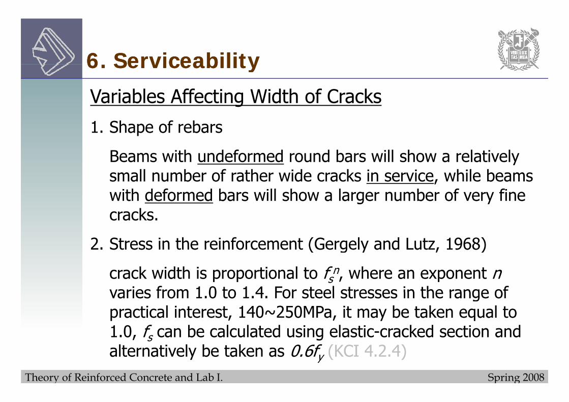
Beams with undeformed round bars will show a relativelyBeams with undeformed round bars will show a relatively small number of rather wide cracks in service, while beams with deformed bars will show a larger number of very fine t de o ed ba s s o a a ge u be o e y ecracks.
2 Stress in the reinforcement (Gergely and Lutz 1968)2. Stress in the reinforcement (Gergely and Lutz, 1968)
crack width is proportional to fsn, where an exponent nvaries from 1 0 to 1 4 For steel stresses in the range ofvaries from 1.0 to 1.4. For steel stresses in the range of practical interest, 140~250MPa, it may be taken equal to 1.0, fs can be calculated using elastic-cracked section and
Theory of Reinforced Concrete and Lab I. Spring 2008
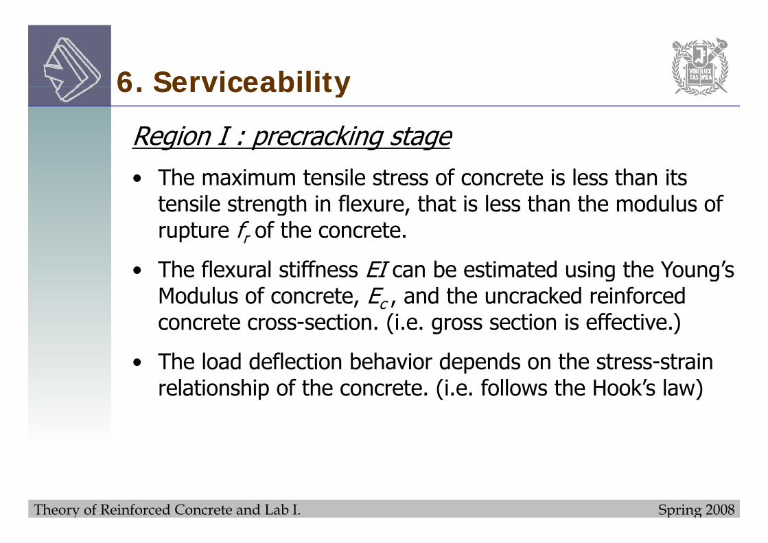
Region I : precracking stageg p g g• The maximum tensile stress of concrete is less than its
tensile strength in flexure, that is less than the modulus oftensile strength in flexure, that is less than the modulus of rupture fr of the concrete.
• The flexural stiffness EI can be estimated using the Young’s• The flexural stiffness EI can be estimated using the Young s Modulus of concrete, Ec , and the uncracked reinforced concrete cross-section. (i.e. gross section is effective.)( g )
• The load deflection behavior depends on the stress-strain relationship of the concrete. (i.e. follows the Hook’s law)relationship of the concrete. (i.e. follows the Hook s law)
Theory of Reinforced Concrete and Lab I. Spring 2008
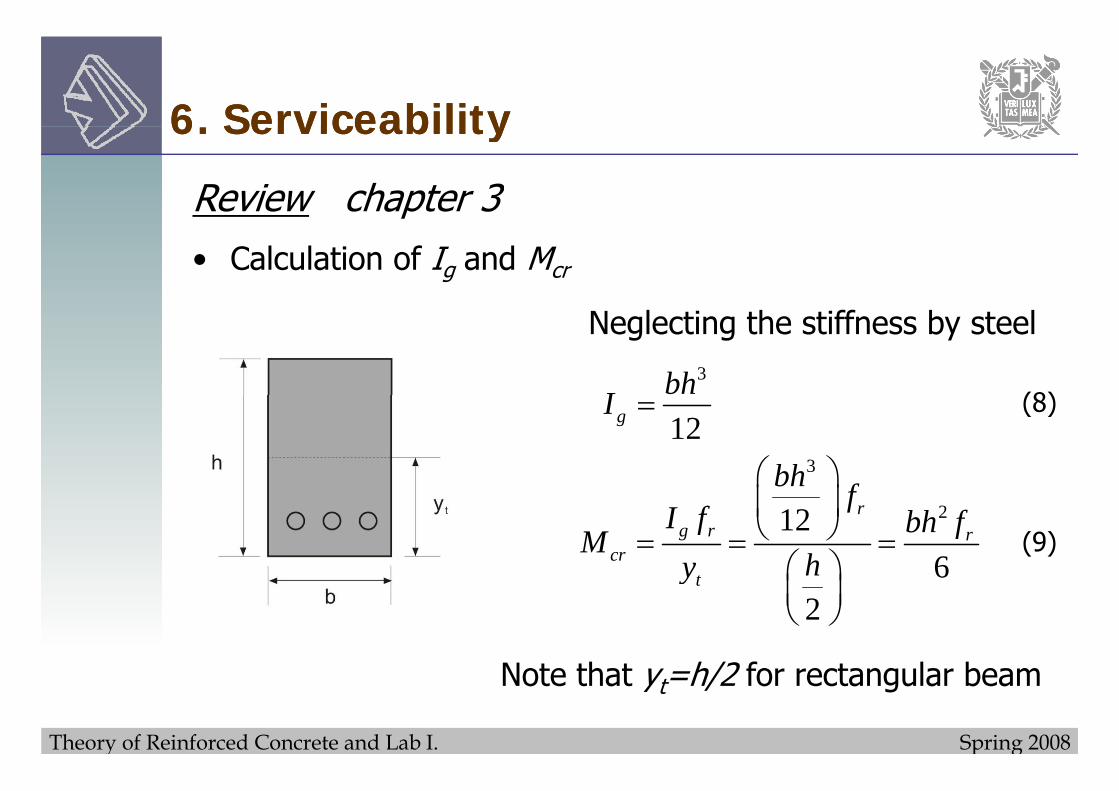
Region I : precracking stage (cont.)g p g g ( )• There are two approaches in estimation of the moment of
inertia I in this region.inertia I in this region.
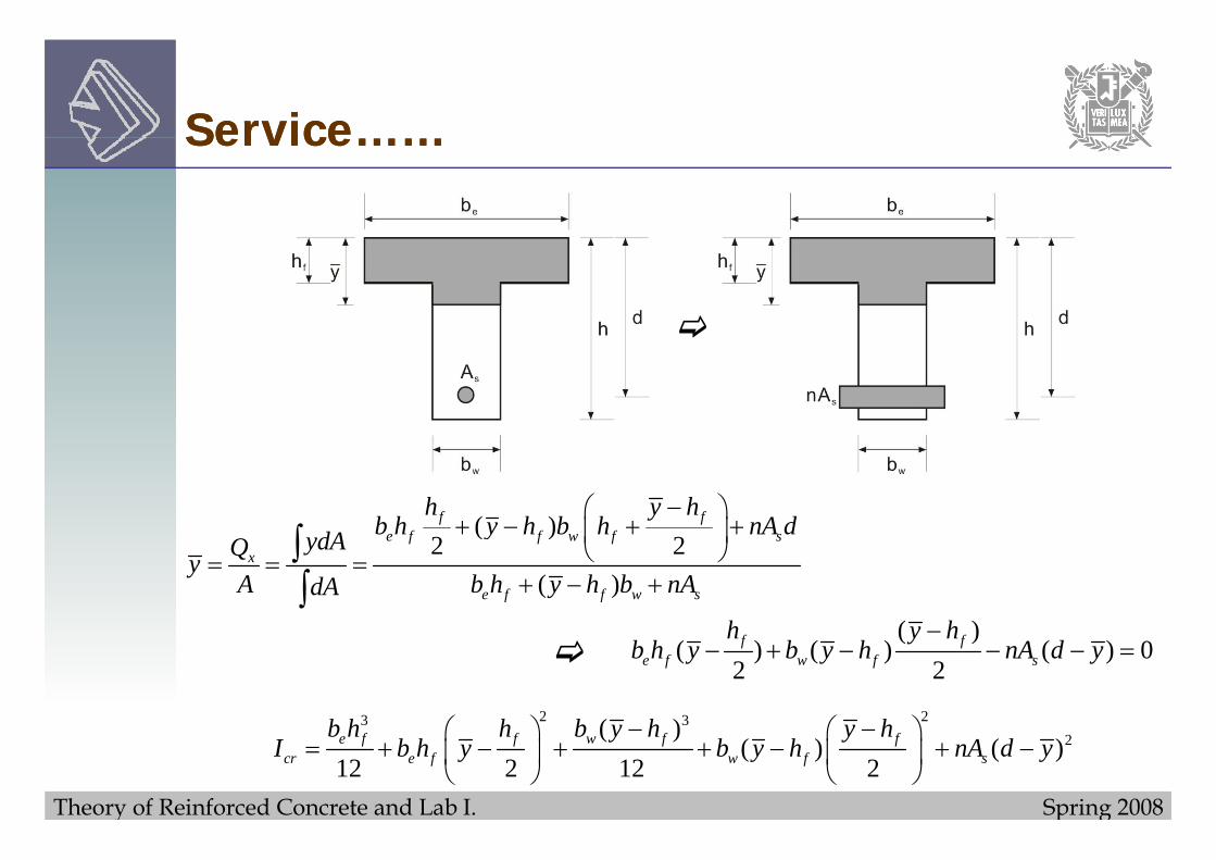
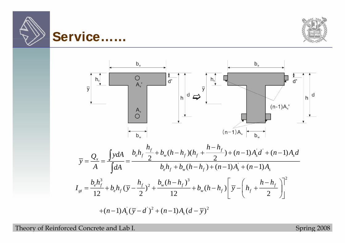
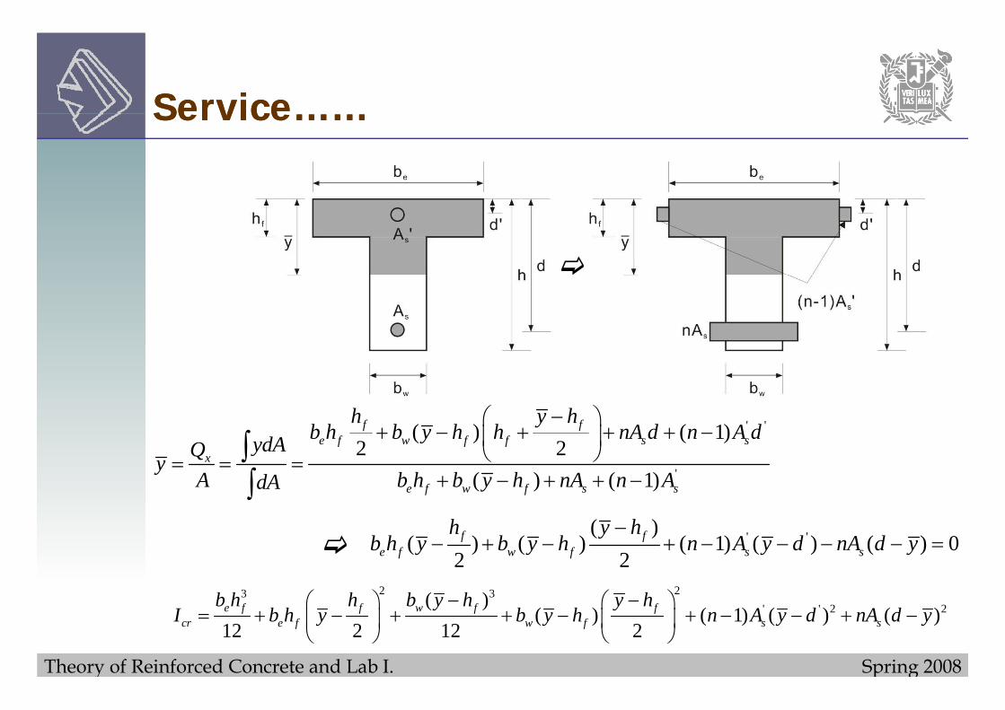
i) Gross section : where Ig is calculated neglecting the presence of any reinforcing steelpresence of any reinforcing steel
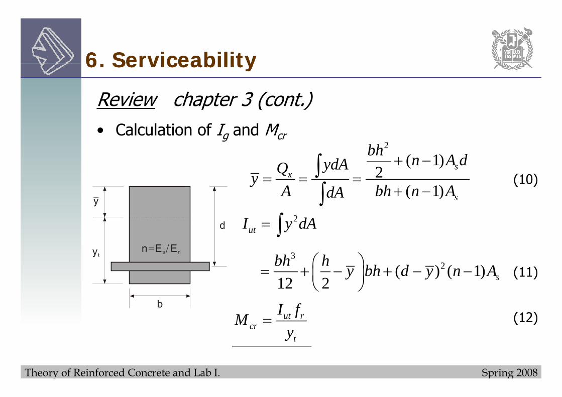
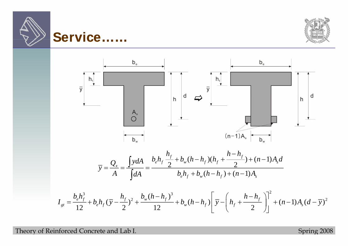
ii) Transformed section : where Igt is calculated taking into account the additional stiffness contributed by the steelaccount the additional stiffness contributed by the steel reinforcement.
Note 1) method ii) is more accurate than i)
2) Igt is often expressed as Iut
Theory of Reinforced Concrete and Lab I. Spring 2008
Region III : postserviceability cracking stageRegion III : postserviceability cracking stage• The load-deflection diagram is considerably flatten in this
i d b i l l i iff f h iregion due to substantial loss in stiffness of the section.
; extensive cracking takes place.
• The beam is considered at this stage to have structurally failed by yielding of the tension steel, and continues to y y g ,deflect without additional loading.
Theory of Reinforced Concrete and Lab I. Spring 2008
Region III : postserviceability cracking stage (cont )Region III : postserviceability cracking stage (cont.)• The cracks continue to open, and the neutral axis continues
t i d til t t l hi f th t hto rise upward until total crushing of the concrete when rupture occurs.
Note
Postyield deflection and limit deflection at failure are not ofPostyield deflection and limit deflection at failure are not of major significant in design and hence are not being discussed in any detail, however, it is IMPORTANT todiscussed in any detail, however, it is IMPORTANT to recognize the reserve deflection capacity as a measure of ductility in structures.
Theory of Reinforced Concrete and Lab I. Spring 2008
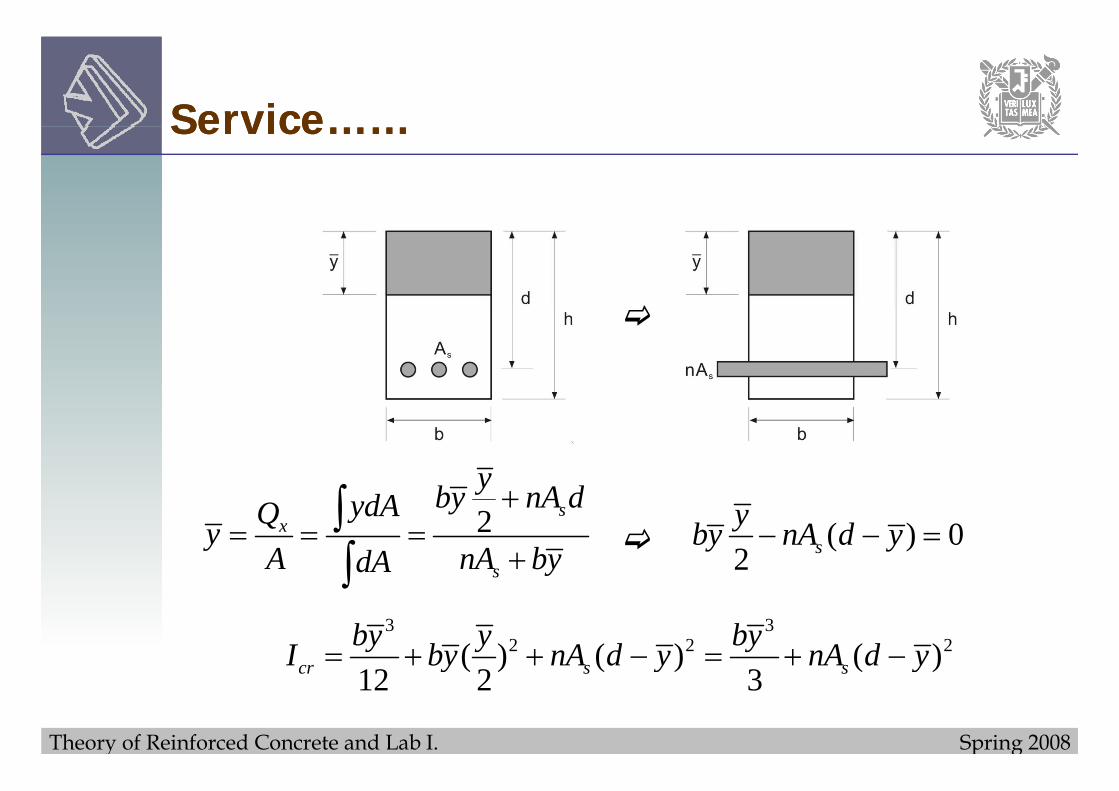
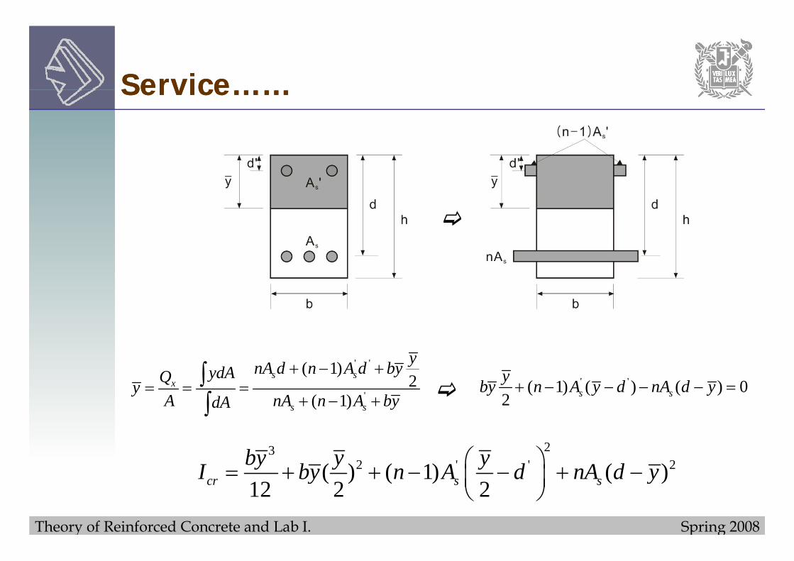
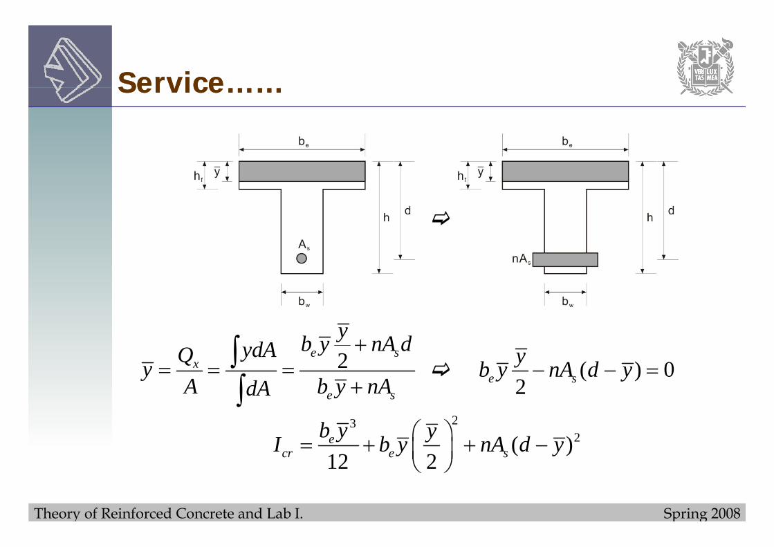
C t f ff ti t f i ti IConcept of effective moment of inertia Ie
• In case of Region II, in realty only of the beam cross-g y ysection is cracked.
; the uncracked segments below the neutral axis along the; the uncracked segments below the neutral axis along the beam span possess SOME degree of stiffness, which contributes to over all beam rigidity.
• Generally, as the load approaches the steel yield load level, the stiffness value approaches EcIcrc cr
• Therefore, actual stiffness lies between EcIg and EcIcr at Region II.
Theory of Reinforced Concrete and Lab I. Spring 2008
DEFLECTIONS DUE TO LONG-TERM LOADS• In addition to deflections that occur IMMEDIATELY,
reinforced concrete members are subjected to added
DEFLECTIONS DUE TO LONG TERM LOADS
reinforced concrete members are subjected to added deflections that occur gradually over long periods.
• These additional deflection are due mainly to CREEP and• These additional deflection are due mainly to CREEP and SHRINKAGE and may eventually become excessive.
C ll d i t b t f t f b• Creep generally dominates, but for some types of members, shrinkage deflections are large and should be considered separatelyseparately.
Theory of Reinforced Concrete and Lab I. Spring 2008
• The initial strain εi increases due to creep by the amount• The initial strain εi increases, due to creep, by the amount εt, while the strain εs in the steel is essentially unchanged.
• Because the rotation of the strain distribution diagram the• Because the rotation of the strain distribution diagram, the neutral axis moves down
t tφ ε< (17)
Theory of Reinforced Concrete and Lab I. Spring 2008
Effect of Concrete Creep on curvatureEffect of Concrete Creep on curvature
• Due to the lowering of the neutral axis associated with creep and the resulting increase in compression area thecreep, and the resulting increase in compression area, the compressive stress required to meet equilibrium is less than before.
; In contrast to cylinder creep test, the beam creep occurs at a gradually diminishing stressat a gradually diminishing stress.
Theory of Reinforced Concrete and Lab I. Spring 2008
Effect of Concrete Creep on curvatureEffect of Concrete Creep on curvature
• With the new neutral axis, the internal lever arm is LESS, requiring an increase in both compressive and tensilerequiring an increase in both compressive and tensile resultant forces.
I f t thi ill i ll i i t d t i• In fact, this will require a small increase in stress and strain in the steel.
εs in not constant as assumed originally.
Theory of Reinforced Concrete and Lab I. Spring 2008
Calculation of Long-Term deflectionCalculation of Long Term deflection
• Due to the complexities mentioned previously, in practice, a simplified empirical approach by a factor λ to obtain thea simplified empirical approach by a factor λ to obtain the additional long term deflection is employed.
Δ λΔΔt = λΔi
, where Δi is the initial elastic deflection (immediate
(18)
deflection) and Δt is the additional long-term deflection due to the combined effect of creep and shrinkage.
Theory of Reinforced Concrete and Lab I. Spring 2008
• If a beam carries a certain sustained load w (e.g. the dead load plus the average traffic load on a bridge) and isload plus the average traffic load on a bridge) and is subject to a short-term HEAVY live load P (e.g. the weight of an unusually heavy vehicle), the maximum to total deflection under this combined loading is obtained as follows.
(1) Calculate the instantaneous deflection Δiw caused by the sustained load w
(2) Calculate the additional long-term deflection Δtw caused by the sustained load w
Theory of Reinforced Concrete and Lab I. Spring 2008
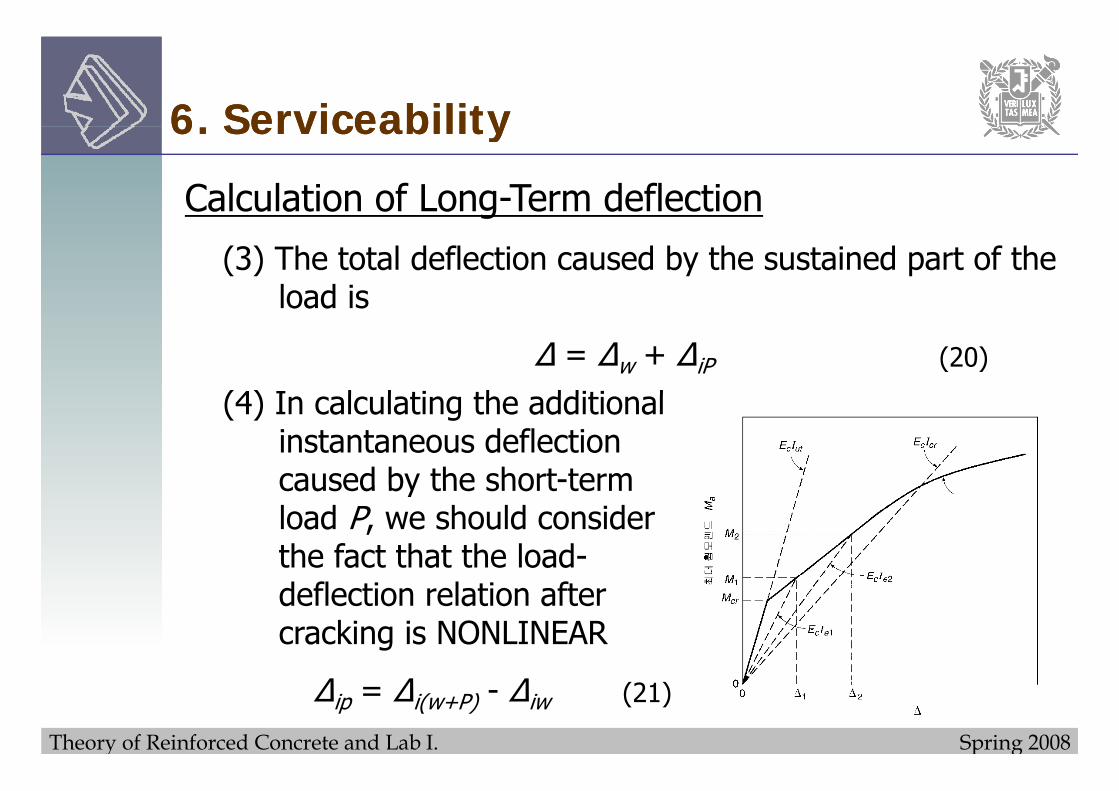
(3) The total deflection caused by the sustained part of the load isload is
Δ = Δw + ΔiP
(4) I l l ti th dditi l(20)
(4) In calculating the additional instantaneous deflection caused by the short-termcaused by the short term load P, we should consider the fact that the load-deflection relation after cracking is NONLINEAR
Theory of Reinforced Concrete and Lab I. Spring 2008
Δ i th t t l i t t d fl ti th t ld bΔi(w+P) is the total instantaneous deflection that would be obtained if w and P were applied simultaneously, calculated by using I determined for the moment causes by w + Pby using Ie determined for the moment causes by w + P.
(5) The total deflection under the sustained load plus heavy short term load isheavy short-term load is
Δ = Δw + ΔiP (22)
Note
In calculations of deflections careful attention must be paid
Theory of Reinforced Concrete and Lab I. Spring 2008
In calculations of deflections, careful attention must be paid to the LOAD HISTORY.
ACI Code 9.5.2, as an option, alike permits use of Ie for continuous prismatic beams to be taken equal to the value obtained from Eq.(25) at midspan ; for cantilever, Iecalculated at the support may be usedcalculated at the support may be used.
Theory of Reinforced Concrete and Lab I. Spring 2008
6. Serviceability6. Serviceability6. Serviceability6. ServiceabilityKCI CODE PROVISIONS FOR DEFLECTION CONTROL
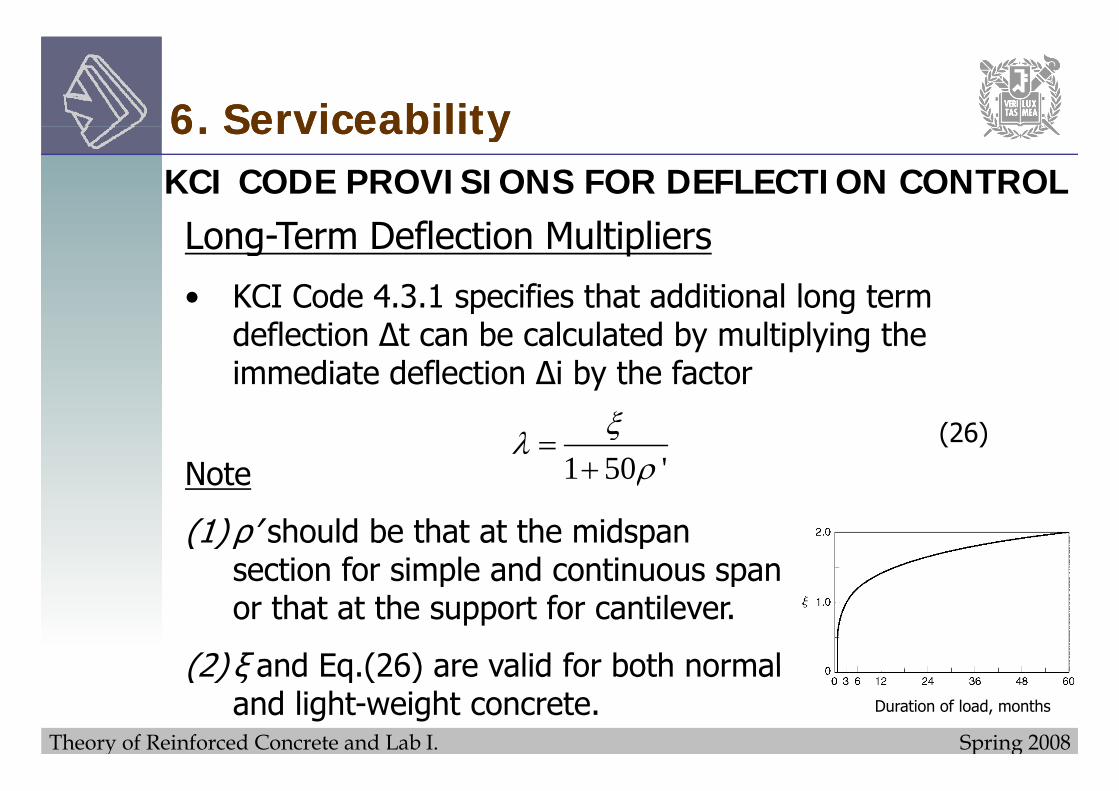
Long-Term Deflection Multipliers
• KCI Code 4.3.1 specifies that additional long termKCI Code 4.3.1 specifies that additional long term deflection Δt can be calculated by multiplying the immediate deflection Δi by the factor
1 50 'ξλρ
=+Note
(26)ρote
(1) ρ’ should be that at the midspan section for simple and continuous spansection for simple and continuous span or that at the support for cantilever.
(2) ξ and Eq (26) are valid for both normal
Theory of Reinforced Concrete and Lab I. Spring 2008
(2) ξ and Eq.(26) are valid for both normal and light-weight concrete. Duration of load, months
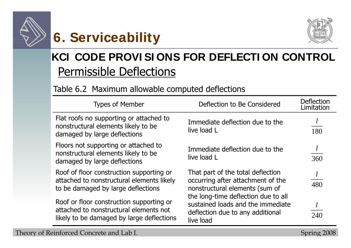
6. Serviceability6. Serviceability6. Serviceability6. ServiceabilityKCI CODE PROVISIONS FOR DEFLECTION CONTROLP i ibl D fl tiPermissible Deflections
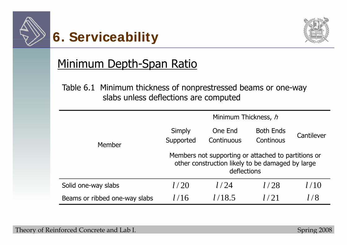
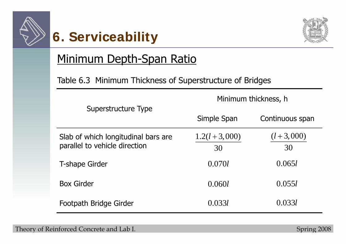
Table 6.2 Maximum allowable computed deflections
Types of Member Deflection to Be Considered DeflectionLimitation
Flat roofs no supporting or attached to t t l l t lik l t b Immediate deflection due to the l
nonstructural elements likely to be damaged by large deflections
Immediate deflection due to the live load L
Floors not supporting or attached to nonstructural elements likely to be Immediate deflection due to the
180
lnonstructural elements likely to be damaged by large deflections live load L
Roof of floor construction supporting or attached to nonstructural elements likely
That part of the total deflection occurring after attachment of the
360
lattached to nonstructural elements likely to be damaged by large deflections
occurring after attachment of the nonstructural elements (sum of the long-time deflection due to all sustained loads and the immediate Roof or floor construction supporting or
attached to nonst ct al elements not
480
l
Theory of Reinforced Concrete and Lab I. Spring 2008
deflection due to any additional live load
attached to nonstructural elements not likely to be damaged by large deflections 240
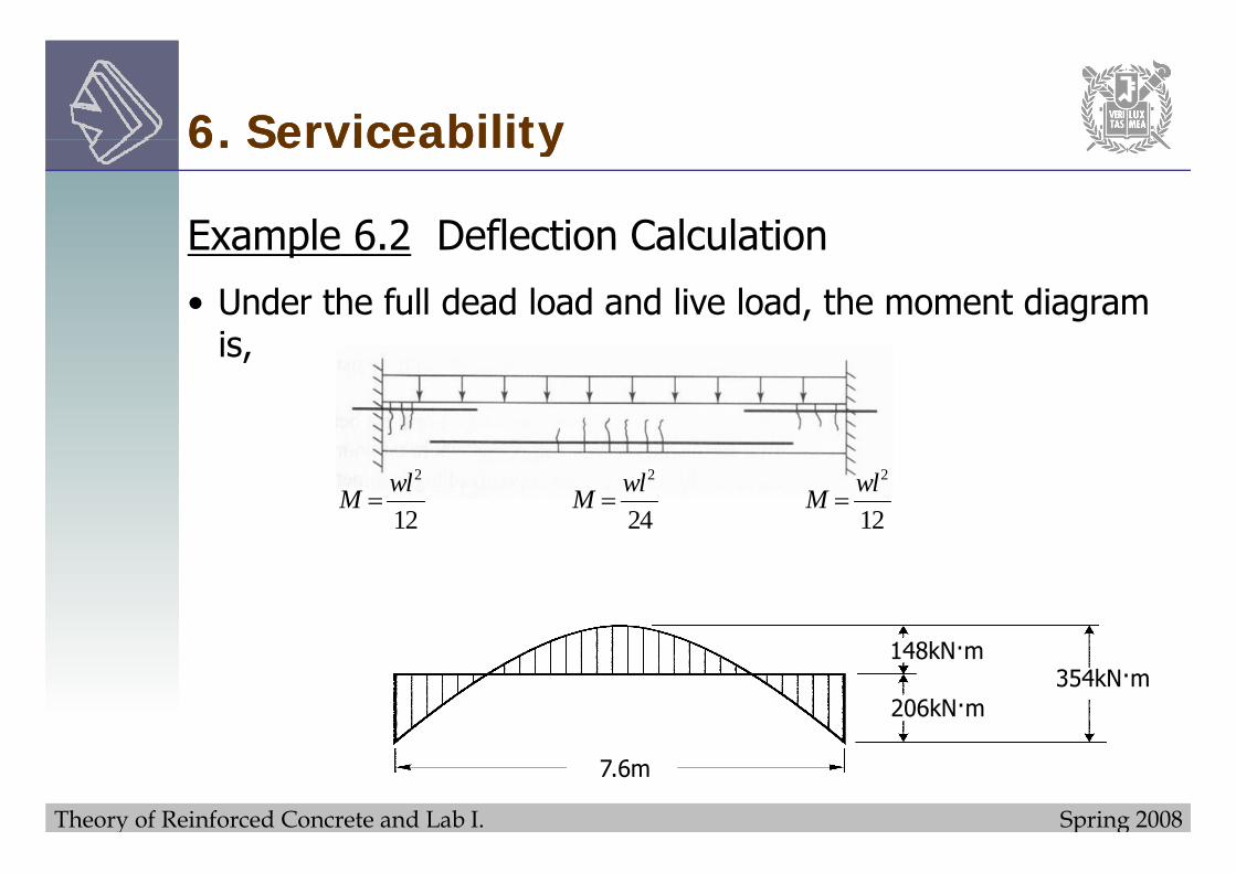
Example 6 2 Deflection CalculationExample 6.2 Deflection Calculation
• This beam will support nonstructural partitions that would be damaged if large deflections were to occurdamaged if large deflections were to occur.
• These nonstructural partitions will be installed shortly after i h i i d d d d l d k ffconstruction shoring is removed and dead loads take effect,
but before significant creep occurs.
• Calculate the part of the total deflection that would adversely affect partitions, i.e., the sum of long-term deflection due to dead and partial live load plus immediate deflection due todead and partial live load plus immediate deflection due to the nonsustained part of the live load.
Theory of Reinforced Concrete and Lab I. Spring 2008