1/28/2015 1 DATA COMMUNICATION Satish Chandra satish0402.weebly.com INTRODUCTION • The The term term telecommunication telecommunication means means communication communication at at a distance distance. • The The word word data data refers refers to to information information presented presented in in whatever whatever form form is is agreed agreed upon upon by by the the parties parties creating creating and and using using the the data data. • The The data data communications communications are are the the exchange exchange of of data data between between two two devices devices via via some some form form of of transmission transmission medium medium such such as as a wire wire cable cable. TELECOMMUNICATIONS • Tele (Far) + Communications • Early telecommunications – smoke signals and drums – visual telegraphy (or semaphore in 1792) • Telegraph and telephone – Telegraph (1839) – Telephone (1876) • Radio and television • Telephony – Voice and Data SYSTEM COMPONENTS Simplified Communications Model Simplified Communications Model The key elements of this model are: • Source ‐ generates data to be transmitted • Transmitter ‐ converts data into transmittable signals • Transmission System ‐ carries data from source to destination • Receiver ‐ converts received signal into data • Destination ‐ takes incoming data
Transcript
1/28/2015
1
DATA COMMUNICATION
Satish Chandrasatish0402.weebly.com
INTRODUCTION
•• TheThe termterm telecommunicationtelecommunication meansmeans communicationcommunicationatat aa distancedistance..
•• AA linklink cancan bebe aa cable,cable, air,air, opticaloptical fiber,fiber, oror anyanymediummedium whichwhich cancan transporttransport aa signalsignal carryingcarryinginformationinformation..
TYPE OF CONNECTION
Point to Point - single transmitter and receiverMultipoint - multiple recipients of single transmission
1/28/2015
5
NETWORK TOPOLOGIESpersonal computer
personal computer
personal computer
personal computer
personal computer
host computer
printerfile server
personal computer
personal computer
personal computer
personal computer
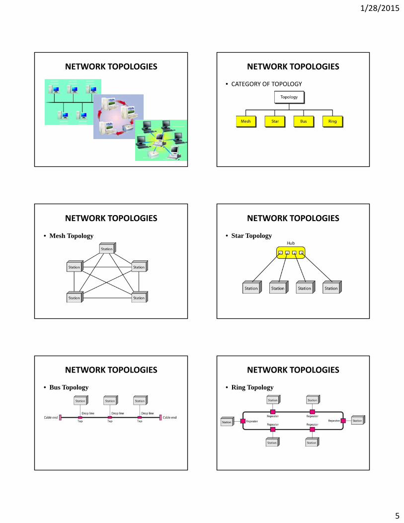
NETWORK TOPOLOGIES
• CATEGORY OF TOPOLOGY
NETWORK TOPOLOGIES
• Mesh Topology
NETWORK TOPOLOGIES
• Star Topology
NETWORK TOPOLOGIES
• Bus Topology
NETWORK TOPOLOGIES
• Ring Topology
1/28/2015
6
NETWORK TOPOLOGIES
• Hybrid Topology:
NETWORKS
• growth of number & power of computers is driving need for interconnection
• also seeing rapid integration of voice, data, image & video technologiesg g
• three broad categories of communications networks:– Local Area Network (LAN)– Wide Area Network (WAN)– Metropolitan Area Network (MAN)
Categories of Networks
• Local Area Networks (LANs)– Short distances– Designed to provide local interconnectivity
• Wide Area Networks (WANs)• Wide Area Networks (WANs)– Long distances– Provide connectivity over very large areas
• Metropolitan Area Networks (MANs)– Provide connectivity over areas such as a city, a
campus
Local Area Networks
• smaller scope– Building or small campus
• usually owned by same organization as attached devicesattached devices
• data rates much higher
• switched LANs, eg Ethernet
• wireless LANs
Local Area Networks (LAN)
• An isolated LAN connecting 12 computers to a hub in a closet
Wide Area Networks
• span a large geographical area
• cross public rights of way
• rely in part on common carrier circuits
• alternative technologies used include:– circuit switching
– packet switching
– frame relay
– Asynchronous Transfer Mode (ATM)
1/28/2015
7
Wide Area Networks Metropolitan Area Networks
• MAN
• middle ground between LAN and WAN
• private or public network
• high speed
• large area
A heterogeneous network made of four WANs and two LANs
THE INTERNET
• Internet evolved from ARPANET– first operational packet network– applied to tactical radio & satellite nets also– had a need for interoperabilityp y– led to standardized TCP/IP protocols
•• ItIt hashas affectedaffected thethe wayway wewe dodo businessbusiness asas wellwell asas thethewayway wewe spendspend ourour leisureleisure timetime..yy pp
•• TheThe InternetInternet isis aa communicationcommunication systemsystem thatthat hashasbroughtbrought aa wealthwealth ofof informationinformation toto ourour fingertipsfingertips andandorganizedorganized itit forfor ourour useuse..
Hierarchical organization of the Internet
1/28/2015
8
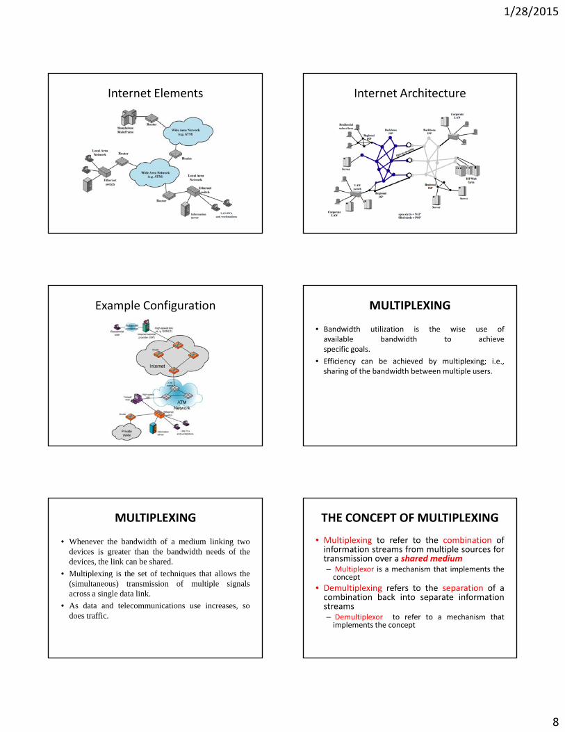
Internet Elements Internet Architecture
Example Configuration MULTIPLEXING
• Bandwidth utilization is the wise use ofavailable bandwidth to achievespecific goals.
• Efficiency can be achieved by multiplexing; i.e.,sharing of the bandwidth between multiple users.
MULTIPLEXING
• Whenever the bandwidth of a medium linking twodevices is greater than the bandwidth needs of thedevices, the link can be shared.
• Multiplexing is the set of techniques that allows thep g q(simultaneous) transmission of multiple signalsacross a single data link.
• As data and telecommunications use increases, sodoes traffic.
THE CONCEPT OF MULTIPLEXING
• Multiplexing to refer to the combination ofinformation streams from multiple sources fortransmission over a shared medium– Multiplexor is a mechanism that implements theconceptconcept
• Demultiplexing refers to the separation of acombination back into separate informationstreams– Demultiplexor to refer to a mechanism thatimplements the concept
1/28/2015
9
Multiplexing and Demultiplexing MULTIPLEXING IN NETWORKS
Main pur
Sharing thpose is ?
e medium
MULTIPLEXING IN NETWORKS
each sender communicates with a single receiverall pairs share a single transmission mediummultiplexor combines information from the sendersfor transmission in such a way that thed l i l h i f i fdemultiplexor can separate the information forreceivers.
MULTIPLEXING
MULTIPLEXER EXAMPLE NETWORK SHARINGNetwork Resources (bandwidth) divided into “pieces”• pieces allocated to calls• resource piece idle if not used by owning call (no sharing)• dividing link bandwidth into “pieces”
– frequency division– time division
1/28/2015
10
FDM and TDM
FDM
frequency
4 users
Example:
time
TDM
frequency
time
Spectrum
• AM: 535 kHz to 1.7 MHz• TV: 54‐88 (VHF, channels 2‐6) and 174‐220 (UHF, channels 7‐13)• Unlicensed vs. licensed
Categorization of Multiplexing Frequency Division Multiplexing
• FDM is an analog multiplexing technique that combines analog signals.
FDM: Multiplexing Process FDM: Demultiplexing Process
1/28/2015
11
FDM: Example
• Assume that a voice channel occupies a bandwidth of 4 kHz.We need to combine three voice channels into a link with abandwidth of 12 kHz, from 20 to 32 kHz. Show theconfiguration, using the frequency domain. Assume thereare no guard bands.g
• Shift (modulate) each of the three voice channels to adifferent bandwidth. We use the 20 to 24 kHz bandwidth forthe first channel, the 24 to 28 kHz bandwidth for the secondchannel, and the 28 to 32 kHz bandwidth for the third oneand then combine them.
FDM: Example
FDM: Bandwidth
• Five channels, each with a 100‐kHz bandwidth, are to bemultiplexed together. What is the minimum bandwidth of thelink if there is a need for a guard band of 10 kHz between thechannels to prevent interference?
Wave Division Multiplexing
• WDM is an analog multiplexing technique to combine optical signals.
WDM: MULTIPLEXING & DEMULIPLEXING TIME DIVISION MULTIPLEXING
• TDM is a digital multiplexing technique forcombining several low‐rate digital channelsinto one high‐rate one.
• In synchronous TDM the data rate of the link• In synchronous TDM, the data rate of the linkis n times faster, and the unit duration is ntimes shorter.
1/28/2015
12
TDM TDM
TDM TDM
Frequency Division Multiplex• Separation of spectrum into smaller frequency bands•Channel gets band of the spectrum for the whole time Advantages:
no dynamic coordination neededworks also for analog signals
Disadvantages:
Channelski
k3 k4 k5 k6gwaste of bandwidth, if traffic distributed unevenlyinflexibleguard spaces
t
1/28/2015
13
Why FDM is for analog signals and TDM is for digital signals?
FDM stands for frequency division multiplexing and it isused only in case of analog signals because analog signalsare continuous in nature and the signal have frequency.
TDM‐stands for time division multiplexing and it is used
6.73
p gonly in case of digital signals because digital signals arediscrete in nature and are in the form of 0 and 1s. and aretime dependent.
ADVANTAGES & DISADVANTAGES OF TDM & FDM
In TDM, different users share the same channel based on time slotsallotted to them. Each user or source is given a particular time slot tosend its information.
1. The entire channel BW is available for a particular time intervalunlike in FDM where the channel BW is split into smaller segments.
6.74
unlike in FDM where the channel BW is split into smaller segments.This enables higher data rates.
2. All users share the same frequency, so spectrum efficiency isincreased. Available channel BW is no more a constraint.


![Twisted Acoustics: Metasurface‐Enabled …(WDM), time-division multiplexing (TDM), and multilevel amplitude/phase modulation,[4–7] data rate of acoustic com-munication is approaching](https://static.documents.pub/doc/80x56/5e9bf93695e5e7674e2807ea/twisted-acoustics-metasurfaceaenabled-wdm-time-division-multiplexing-tdm.jpg)


