Shape-morphing mechanical metamaterials Caigui Jiang 1 , Florian Rist 1 , Hui Wang 1 , Johannes Wallner 2,∗ , Helmut Pottmann 1 Abstract Small-scale cut and fold patterns imposed on sheet material enable its morphing into three- dimensional shapes. This manufacturing paradigm has been receiving much attention in recent years and poses challenges in both fabrication and computation. It is intimately connected with the interpretation of patterned sheets as mechanical metamaterials, typically of negative Poisson ratio. We here present an affirmative solution to a fundamental geometric question, namely the targeted programming of a shape morph. We use optimization to compute kirigami patterns that realize a morph between shapes, in particular between a flat sheet and a surface in space. The shapes involved can be arbitrary; in fact we are able to approximate any mapping between shapes whose principal distortions do not exceed certain bounds. This amounts to a solution of the so-called inverse problem for kirigami cut and fold patterns. The methods we employ include a differential-geometric interpretation of the morph, besides drawing on recent progress in geometric computing. Keywords: kirigami, auxetic materials, metamaterials, shape morphing, computational fabrication, 1. Introduction In recent years there has been growing interest in what we would like to call geometric materials, namely mechanical metamaterials capable of shape morphing. One particular way these can be achieved is via folding flat sheet material [1, 2, 3, 4, 5, 6]. Another route is offered by cut and fold patterns imposed on flat sheets, dissecting them into small parts connected by hinges, with subsequent actuation causing the morph. Cuts in addition to folds (kirigami) considerably add to the degrees of freedom that are available for morphing. It is this idea that is studied in the present paper – see Fig. 1 for an example. This approach to generating 3D shapes is particularly valuable in situations where this shape is to be endowed with technology more easily printed onto a 2D sheet. A prime example is electronics, where cutting and folding is an alternative to other ways of manufacturing three-dimensional circuit carriers like molding [7]. For this reason, folding has been proposed for pop-up robots on Mars [8]. A typical feature of geometric metamaterials is their auxetic behaviour [9, 10, 11], with ex- pansion under tension being caused by gaps opening when micro-elements are rotating. Analysis of this behaviour is the key for treating metamaterials by differential-geometric methods as we are going to do in this paper. The cut and fold patterns involved in the geometric materials we have in mind are repetitive, following a periodic tesselation of the plane by triangles [12, 13, 14], quadrilaterals [15], hexagons ∗ Corresponding Author 1 King Abdullah University of Science and Technology 2 Graz University of Technology Preprint submitted to Elsevier October 27, 2021
Transcript
Shape-morphing mechanical metamaterials
Caigui Jiang1, Florian Rist1, Hui Wang1, Johannes Wallner2,∗, Helmut Pottmann1
Abstract
Small-scale cut and fold patterns imposed on sheet material enable its morphing into three-dimensional shapes. This manufacturing paradigm has been receiving much attention in recentyears and poses challenges in both fabrication and computation. It is intimately connected withthe interpretation of patterned sheets as mechanical metamaterials, typically of negative Poissonratio. We here present an affirmative solution to a fundamental geometric question, namely thetargeted programming of a shape morph. We use optimization to compute kirigami patternsthat realize a morph between shapes, in particular between a flat sheet and a surface in space.The shapes involved can be arbitrary; in fact we are able to approximate any mapping betweenshapes whose principal distortions do not exceed certain bounds. This amounts to a solutionof the so-called inverse problem for kirigami cut and fold patterns. The methods we employinclude a differential-geometric interpretation of the morph, besides drawing on recent progressin geometric computing.
In recent years there has been growing interest in what we would like to call geometric materials,namely mechanical metamaterials capable of shape morphing. One particular way these can beachieved is via folding flat sheet material [1, 2, 3, 4, 5, 6]. Another route is offered by cut andfold patterns imposed on flat sheets, dissecting them into small parts connected by hinges, withsubsequent actuation causing the morph. Cuts in addition to folds (kirigami) considerably addto the degrees of freedom that are available for morphing. It is this idea that is studied in thepresent paper – see Fig. 1 for an example. This approach to generating 3D shapes is particularlyvaluable in situations where this shape is to be endowed with technology more easily printedonto a 2D sheet. A prime example is electronics, where cutting and folding is an alternative toother ways of manufacturing three-dimensional circuit carriers like molding [7]. For this reason,folding has been proposed for pop-up robots on Mars [8].
A typical feature of geometric metamaterials is their auxetic behaviour [9, 10, 11], with ex-pansion under tension being caused by gaps opening when micro-elements are rotating. Analysisof this behaviour is the key for treating metamaterials by differential-geometric methods as weare going to do in this paper.
The cut and fold patterns involved in the geometric materials we have in mind are repetitive,following a periodic tesselation of the plane by triangles [12, 13, 14], quadrilaterals [15], hexagons
∗Corresponding Author1King Abdullah University of Science and Technology2Graz University of Technology
Preprint submitted to Elsevier October 27, 2021
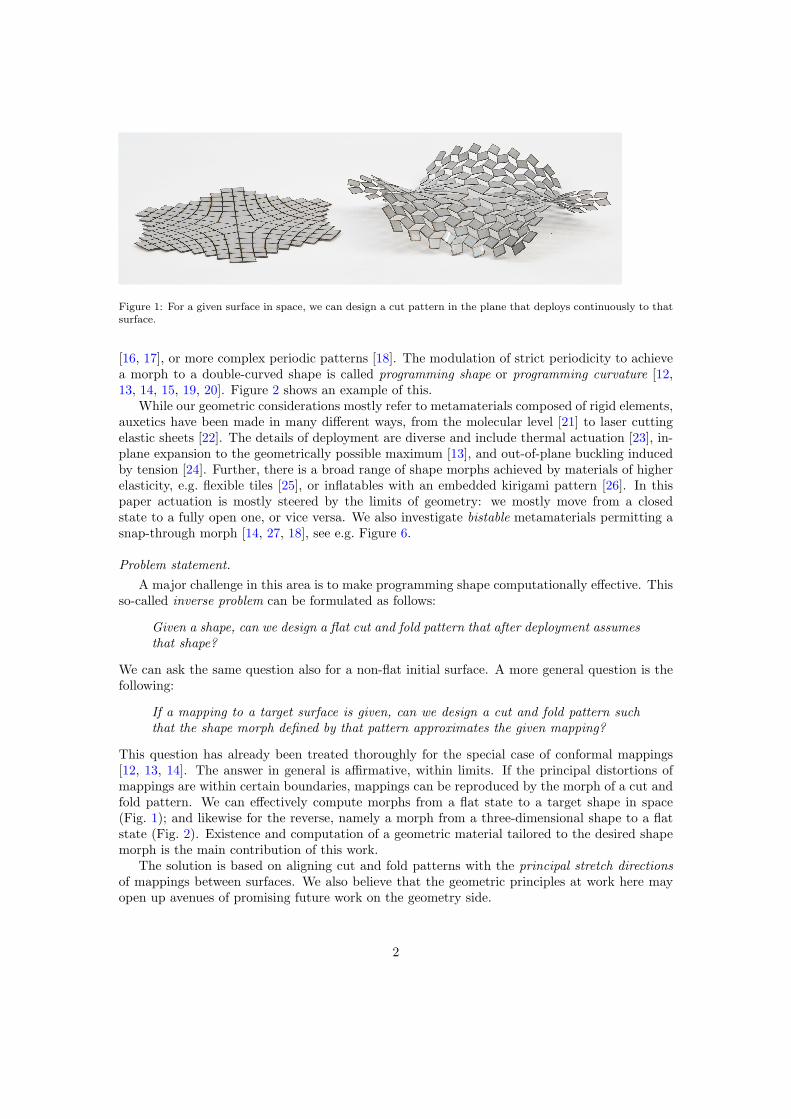
Figure 1: For a given surface in space, we can design a cut pattern in the plane that deploys continuously to thatsurface.
[16, 17], or more complex periodic patterns [18]. The modulation of strict periodicity to achievea morph to a double-curved shape is called programming shape or programming curvature [12,13, 14, 15, 19, 20]. Figure 2 shows an example of this.
While our geometric considerations mostly refer to metamaterials composed of rigid elements,auxetics have been made in many different ways, from the molecular level [21] to laser cuttingelastic sheets [22]. The details of deployment are diverse and include thermal actuation [23], in-plane expansion to the geometrically possible maximum [13], and out-of-plane buckling inducedby tension [24]. Further, there is a broad range of shape morphs achieved by materials of higherelasticity, e.g. flexible tiles [25], or inflatables with an embedded kirigami pattern [26]. In thispaper actuation is mostly steered by the limits of geometry: we mostly move from a closedstate to a fully open one, or vice versa. We also investigate bistable metamaterials permitting asnap-through morph [14, 27, 18], see e.g. Figure 6.
Problem statement.
A major challenge in this area is to make programming shape computationally effective. Thisso-called inverse problem can be formulated as follows:
Given a shape, can we design a flat cut and fold pattern that after deployment assumes
that shape?
We can ask the same question also for a non-flat initial surface. A more general question is thefollowing:
If a mapping to a target surface is given, can we design a cut and fold pattern such
that the shape morph defined by that pattern approximates the given mapping?
This question has already been treated thoroughly for the special case of conformal mappings[12, 13, 14]. The answer in general is affirmative, within limits. If the principal distortions ofmappings are within certain boundaries, mappings can be reproduced by the morph of a cut andfold pattern. We can effectively compute morphs from a flat state to a target shape in space(Fig. 1); and likewise for the reverse, namely a morph from a three-dimensional shape to a flatstate (Fig. 2). Existence and computation of a geometric material tailored to the desired shapemorph is the main contribution of this work.
The solution is based on aligning cut and fold patterns with the principal stretch directions
of mappings between surfaces. We also believe that the geometric principles at work here mayopen up avenues of promising future work on the geometry side.
2
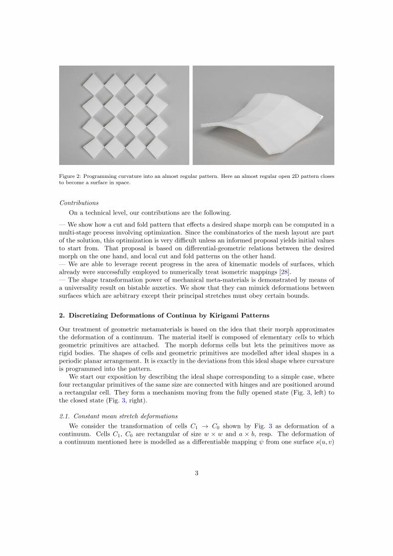
Figure 2: Programming curvature into an almost regular pattern. Here an almost regular open 2D pattern closesto become a surface in space.
Contributions
On a technical level, our contributions are the following.
— We show how a cut and fold pattern that effects a desired shape morph can be computed in amulti-stage process involving optimization. Since the combinatorics of the mesh layout are partof the solution, this optimization is very difficult unless an informed proposal yields initial valuesto start from. That proposal is based on differential-geometric relations between the desiredmorph on the one hand, and local cut and fold patterns on the other hand.— We are able to leverage recent progress in the area of kinematic models of surfaces, whichalready were successfully employed to numerically treat isometric mappings [28].— The shape transformation power of mechanical meta-materials is demonstrated by means ofa universality result on bistable auxetics. We show that they can mimick deformations betweensurfaces which are arbitrary except their principal stretches must obey certain bounds.
2. Discretizing Deformations of Continua by Kirigami Patterns
Our treatment of geometric metamaterials is based on the idea that their morph approximatesthe deformation of a continuum. The material itself is composed of elementary cells to whichgeometric primitives are attached. The morph deforms cells but lets the primitives move asrigid bodies. The shapes of cells and geometric primitives are modelled after ideal shapes in aperiodic planar arrangement. It is exactly in the deviations from this ideal shape where curvatureis programmed into the pattern.
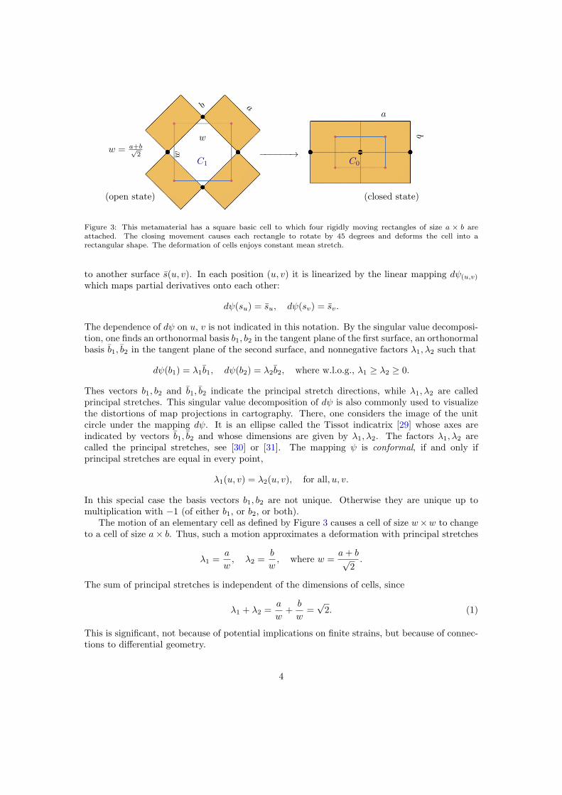
We start our exposition by describing the ideal shape corresponding to a simple case, wherefour rectangular primitives of the same size are connected with hinges and are positioned arounda rectangular cell. They form a mechanism moving from the fully opened state (Fig. 3, left) tothe closed state (Fig. 3, right).
2.1. Constant mean stretch deformations
We consider the transformation of cells C1 → C0 shown by Fig. 3 as deformation of acontinuum. Cells C1, C0 are rectangular of size w × w and a × b, resp. The deformation ofa continuum mentioned here is modelled as a differentiable mapping ψ from one surface s(u, v)
3
ab
w
w
C1
w = a+b√2
(open state)
−−−−−−→
a
b
C0
(closed state)
Figure 3: This metamaterial has a square basic cell to which four rigidly moving rectangles of size a × b areattached. The closing movement causes each rectangle to rotate by 45 degrees and deforms the cell into arectangular shape. The deformation of cells enjoys constant mean stretch.
to another surface s(u, v). In each position (u, v) it is linearized by the linear mapping dψ(u,v)
which maps partial derivatives onto each other:
dψ(su) = su, dψ(sv) = sv.
The dependence of dψ on u, v is not indicated in this notation. By the singular value decomposi-tion, one finds an orthonormal basis b1, b2 in the tangent plane of the first surface, an orthonormalbasis b1, b2 in the tangent plane of the second surface, and nonnegative factors λ1, λ2 such that
Thes vectors b1, b2 and b1, b2 indicate the principal stretch directions, while λ1, λ2 are calledprincipal stretches. This singular value decomposition of dψ is also commonly used to visualizethe distortions of map projections in cartography. There, one considers the image of the unitcircle under the mapping dψ. It is an ellipse called the Tissot indicatrix [29] whose axes areindicated by vectors b1, b2 and whose dimensions are given by λ1, λ2. The factors λ1, λ2 arecalled the principal stretches, see [30] or [31]. The mapping ψ is conformal, if and only ifprincipal stretches are equal in every point,
λ1(u, v) = λ2(u, v), for all, u, v.
In this special case the basis vectors b1, b2 are not unique. Otherwise they are unique up tomultiplication with −1 (of either b1, or b2, or both).
The motion of an elementary cell as defined by Figure 3 causes a cell of size w×w to changeto a cell of size a× b. Thus, such a motion approximates a deformation with principal stretches
λ1 =a
w, λ2 =
b
w, where w =
a+ b√2.
The sum of principal stretches is independent of the dimensions of cells, since
λ1 + λ2 =a
w+b
w=
√2. (1)
This is significant, not because of potential implications on finite strains, but because of connec-tions to differential geometry.
4
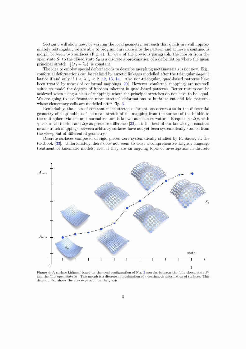
Section 3 will show how, by varying the local geometry, but such that quads are still approx-imately rectangular, we are able to program curvature into the pattern and achieve a continuousmorph between two surfaces (Fig. 4). In view of the previous paragraph, the morph from theopen state S1 to the closed state S0 is a discrete approximation of a deformation where the meanprincipal stretch, 1
2 (λ1 + λ2), is constant.The idea to employ special deformations to describe morphing metamaterials is not new. E.g.,
conformal deformations can be realized by auxetic linkages modelled after the triangular kagome
lattice if and only if 1 < λ1,2 < 2 [12, 13, 14]. Also non-triangular, quad-based patterns havebeen treated by means of conformal mappings [20]. However, conformal mappings are not wellsuited to model the degrees of freedom inherent in quad-based patterns. Better results can beachieved when using a class of mappings where the principal stretches do not have to be equal.We are going to use “constant mean stretch” deformations to initialize cut and fold patternswhose elementary cells are modelled after Fig. 3.
Remarkably, the class of constant mean stretch deformations occurs also in the differentialgeometry of soap bubbles. The mean stretch of the mapping from the surface of the bubble tothe unit sphere via the unit normal vectors is known as mean curvature. It equals γ ·∆p, withγ as surface tension and ∆p as pressure difference [32]. To the best of our knowledge, constantmean stretch mappings between arbitrary surfaces have not yet been systematically studied fromthe viewpoint of differential geometry.
Discrete surfaces composed of rigid pieces were systematically studied by R. Sauer, cf. thetextbook [33]. Unfortunately there does not seem to exist a comprehensive English languagetreatment of kinematic models, even if they are an ongoing topic of investigation in discrete
01
state
Amax
Amin
S0
S1
Figure 4: A surface kirigami based on the local configuration of Fig. 3 morphs between the fully closed state S0
and the fully open state S1. This morph is a discrete approximation of a continuous deformation of surfaces. Thisdiagram also shows the area expansion on the y axis.
5
differential geometry — see e.g. [34] or [35].The design principle of §2.1 can be applied to different and more general quad-based geometric
metamaterials. One possible generalization concerns quad-based cut patterns that do not openfully. Rather, each incision opens to a hole that is roughly diamond-shaped, with the degree ofopening depending on the location. In this way more general deformations between surfaces canbe simulated. The basic idea of Fig. 3 has to be modified in obvious ways. We will briefly treatsuch generalizations in § 4.1.
2.2. Bistable quad-based auxetics
The principle of programming curvature can be applied to any quad-based regular planarpattern. We demonstrate how to treat a recently proposed bistable metamaterial [18] and showthat it is capable of realizing more arbitrary morphs between 3D shapes than the constant meanstretch case discussed above.
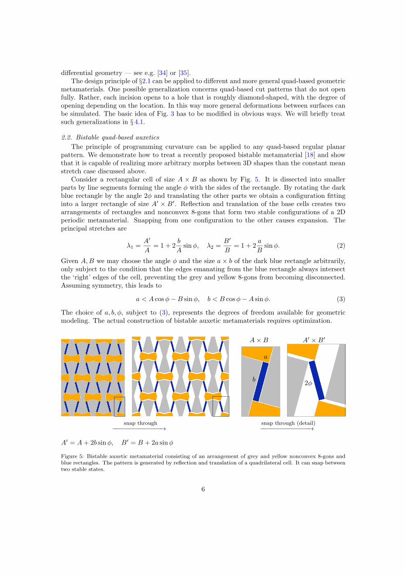
Consider a rectangular cell of size A × B as shown by Fig. 5. It is dissected into smallerparts by line segments forming the angle φ with the sides of the rectangle. By rotating the darkblue rectangle by the angle 2φ and translating the other parts we obtain a configuration fittinginto a larger rectangle of size A′ × B′. Reflection and translation of the base cells creates twoarrangements of rectangles and nonconvex 8-gons that form two stable configurations of a 2Dperiodic metamaterial. Snapping from one configuration to the other causes expansion. Theprincipal stretches are
λ1 =A′
A= 1 + 2
b
Asinφ, λ2 =
B′
B= 1 + 2
a
Bsinφ. (2)
Given A,B we may choose the angle φ and the size a× b of the dark blue rectangle arbitrarily,only subject to the condition that the edges emanating from the blue rectangle always intersectthe ‘right’ edges of the cell, preventing the grey and yellow 8-gons from becoming disconnected.Assuming symmetry, this leads to
a < A cosφ−B sinφ, b < B cosφ−A sinφ. (3)
The choice of a, b, φ, subject to (3), represents the degrees of freedom available for geometricmodeling. The actual construction of bistable auxetic metamaterials requires optimization.
a
b
−−−−−−−−−−−−−−→
snap through−−−−−−−−−−−−−−→
snap through (detail)
2φ
A×B A′ ×B′
A′ = A+ 2b sinφ, B′ = B + 2a sinφ
Figure 5: Bistable auxetic metamaterial consisting of an arrangement of grey and yellow nonconvex 8-gons andblue rectangles. The pattern is generated by reflection and translation of a quadrilateral cell. It can snap betweentwo stable states.
6
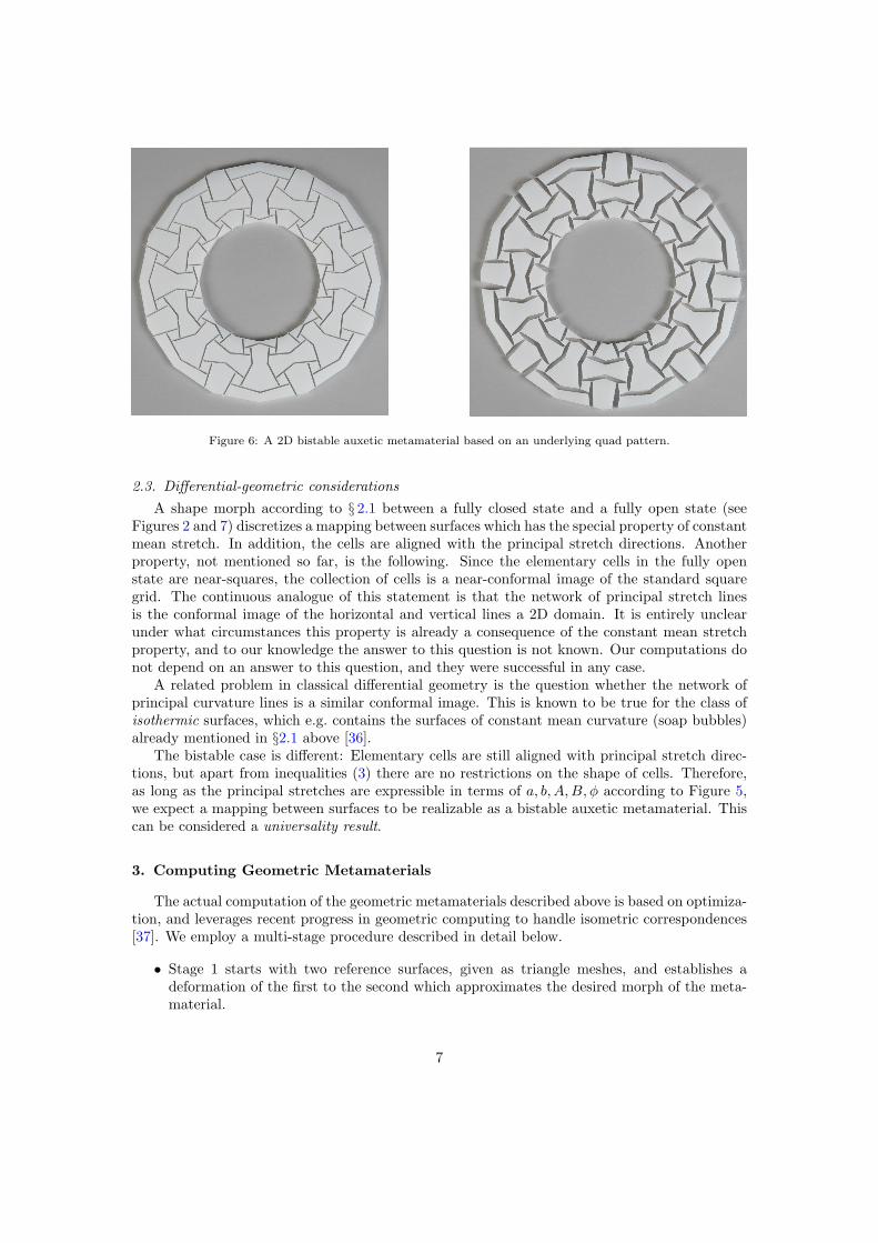
Figure 6: A 2D bistable auxetic metamaterial based on an underlying quad pattern.
2.3. Differential-geometric considerations
A shape morph according to § 2.1 between a fully closed state and a fully open state (seeFigures 2 and 7) discretizes a mapping between surfaces which has the special property of constantmean stretch. In addition, the cells are aligned with the principal stretch directions. Anotherproperty, not mentioned so far, is the following. Since the elementary cells in the fully openstate are near-squares, the collection of cells is a near-conformal image of the standard squaregrid. The continuous analogue of this statement is that the network of principal stretch linesis the conformal image of the horizontal and vertical lines a 2D domain. It is entirely unclearunder what circumstances this property is already a consequence of the constant mean stretchproperty, and to our knowledge the answer to this question is not known. Our computations donot depend on an answer to this question, and they were successful in any case.
A related problem in classical differential geometry is the question whether the network ofprincipal curvature lines is a similar conformal image. This is known to be true for the class ofisothermic surfaces, which e.g. contains the surfaces of constant mean curvature (soap bubbles)already mentioned in §2.1 above [36].
The bistable case is different: Elementary cells are still aligned with principal stretch direc-tions, but apart from inequalities (3) there are no restrictions on the shape of cells. Therefore,as long as the principal stretches are expressible in terms of a, b, A,B, φ according to Figure 5,we expect a mapping between surfaces to be realizable as a bistable auxetic metamaterial. Thiscan be considered a universality result.
3. Computing Geometric Metamaterials
The actual computation of the geometric metamaterials described above is based on optimiza-tion, and leverages recent progress in geometric computing to handle isometric correspondences[37]. We employ a multi-stage procedure described in detail below.
• Stage 1 starts with two reference surfaces, given as triangle meshes, and establishes adeformation of the first to the second which approximates the desired morph of the meta-material.
7
• Stage 2 uses a Levenberg-Marquardt algorithm [38] to optimize these so as to have thecorrect dimensions.
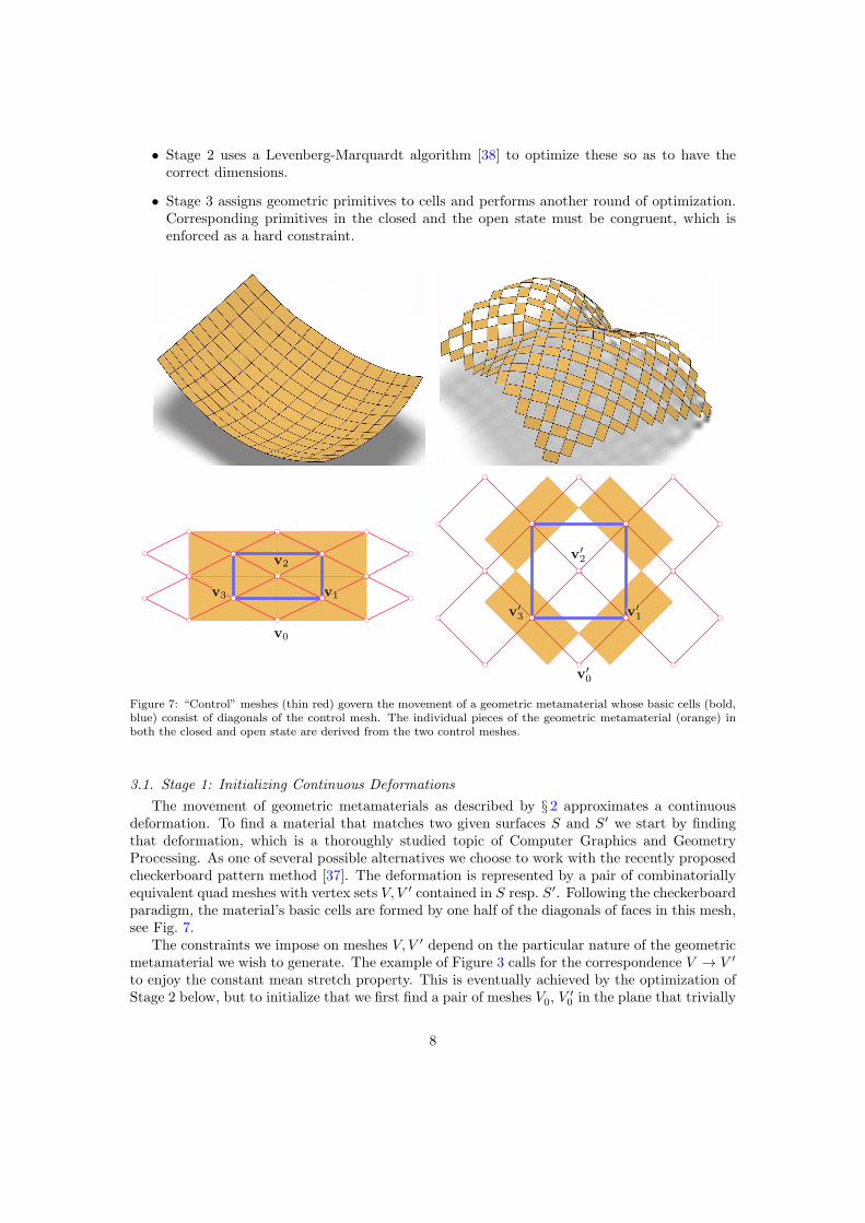
• Stage 3 assigns geometric primitives to cells and performs another round of optimization.Corresponding primitives in the closed and the open state must be congruent, which isenforced as a hard constraint.
Figure 7: “Control” meshes (thin red) govern the movement of a geometric metamaterial whose basic cells (bold,blue) consist of diagonals of the control mesh. The individual pieces of the geometric metamaterial (orange) inboth the closed and open state are derived from the two control meshes.
The movement of geometric metamaterials as described by § 2 approximates a continuousdeformation. To find a material that matches two given surfaces S and S′ we start by findingthat deformation, which is a thoroughly studied topic of Computer Graphics and GeometryProcessing. As one of several possible alternatives we choose to work with the recently proposedcheckerboard pattern method [37]. The deformation is represented by a pair of combinatoriallyequivalent quad meshes with vertex sets V, V ′ contained in S resp. S′. Following the checkerboardparadigm, the material’s basic cells are formed by one half of the diagonals of faces in this mesh,see Fig. 7.
The constraints we impose on meshes V, V ′ depend on the particular nature of the geometricmetamaterial we wish to generate. The example of Figure 3 calls for the correspondence V → V ′
to enjoy the constant mean stretch property. This is eventually achieved by the optimization ofStage 2 below, but to initialize that we first find a pair of meshes V0, V
′0 in the plane that trivially
8
V V ′
V0
V ′0
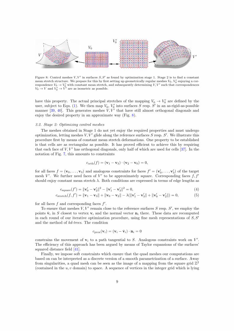
Figure 8: Control meshes V, V ′ in surfaces S, S′ as found by optimization stage 1. Stage 2 is to find a constantmean stretch structure. We prepare for this by first setting up geometrically regular meshes V0, V ′
0enjoying a cor-
respondence V0 → V ′
0with constant mean stretch, and subsequently determining V, V ′ such that correspondences
V0 → V and V ′
0→ V ′ are as isometric as possible.
have this property. The actual principal stretches of the mapping V0 → V ′0 are defined by the
user, subject to Equ. (1). We then map V0, V′0 into surfaces S resp. S′ in an as-rigid-as-possible
manner [39, 40]. This generates meshes V, V ′ that have still almost orthogonal diagonals andenjoy the desired property in an approximate way (Fig. 8).
3.2. Stage 2: Optimizing control meshes
The meshes obtained in Stage 1 do not yet enjoy the required properties and must undergooptimization, letting meshes V, V ′ glide along the reference surfaces S resp. S′. We illustrate thisprocedure first by means of constant mean stretch deformations. One property to be establishedis that cells are as rectangular as possible. It has proved efficient to achieve this by requiringthat each face of V, V ′ has orthogonal diagonals, only half of which are used for cells [37]. In thenotation of Fig. 7, this amounts to constraints
corth(f) = (v1 − v3) · (v2 − v0) = 0,
for all faces f = (v0, . . . ,v3) and analogous constraints for faces f ′ = (v′0, . . . ,v
′3) of the target
mesh V ′. We further need faces of V ′ to be approximately square. Corresponding faces f, f ′
should enjoy constant mean stretch λ. Both conditions are expressed in terms of edge lengths as
csquare(f′) = ‖v′
0 − v′2‖2 − ‖v′
1 − v′3‖2 = 0, (4)
cstretch(f, f′) = ‖v1 − v3‖+ ‖v0 − v2‖ − λ(‖v′
1 − v′3‖+ ‖v′
0 − v′2‖) = 0, (5)
for all faces f and corresponding faces f ′.To ensure that meshes V, V ′ remain close to the reference surfaces S resp. S′, we employ the
points vi in S closest to vertex vi and the normal vector ni there. These data are recomputedin each round of our iterative optimization procedure, using fine mesh representations of S, S′
and the method of kd-trees. The condition
cprox(vi) = (vi − vi) · ni = 0
constrains the movement of vi to a path tangential to S. Analogous constraints work on V ′.The efficiency of this approach has been argued by means of Taylor expansions of the surfaces’squared distance field [41].
Finally, we impose soft constraints which ensure that the quad meshes our computations arebased on can be interpreted as a discrete version of a smooth parametrization of a surface. Awayfrom singularities, a quad mesh can be seen as the image of a mapping from the square grid Z
2
(contained in the u, v domain) to space. A sequence of vertices in the integer grid which is lying
9
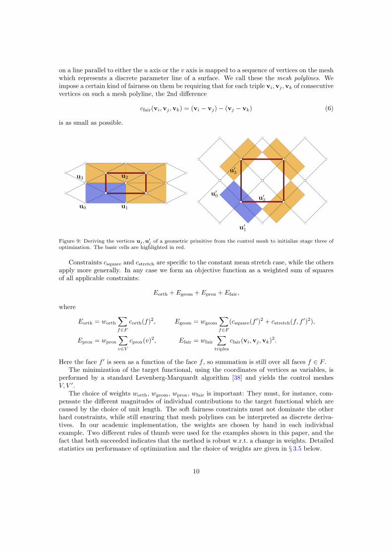
on a line parallel to either the u axis or the v axis is mapped to a sequence of vertices on the meshwhich represents a discrete parameter line of a surface. We call these the mesh polylines. Weimpose a certain kind of fairness on them be requiring that for each triple vi,vj ,vk of consecutivevertices on such a mesh polyline, the 2nd difference
j of a geometric primitive from the control mesh to initialize stage three ofoptimization. The basic cells are highlighted in red.
Constraints csquare and cstretch are specific to the constant mean stretch case, while the othersapply more generally. In any case we form an objective function as a weighted sum of squaresof all applicable constraints:
Eorth + Egeom + Eprox + Efair,
where
Eorth = worth
∑
f∈F
corth(f)2, Egeom = wgeom
∑
f∈F
(csquare(f′)2 + cstretch(f, f
′)2),
Eprox = wprox
∑
v∈V
cprox(v)2, Efair = wfair
∑
triples
cfair(vi,vj ,vk)2.
Here the face f ′ is seen as a function of the face f , so summation is still over all faces f ∈ F .The minimization of the target functional, using the coordinates of vertices as variables, is
performed by a standard Levenberg-Marquardt algorithm [38] and yields the control meshesV, V ′.
The choice of weights worth, wgeom, wprox, wfair is important: They must, for instance, com-pensate the different magnitudes of individual contributions to the target functional which arecaused by the choice of unit length. The soft fairness constraints must not dominate the otherhard constraints, while still ensuring that mesh polylines can be interpreted as discrete deriva-tives. In our academic implementation, the weights are chosen by hand in each individualexample. Two different rules of thumb were used for the examples shown in this paper, and thefact that both succeeded indicates that the method is robust w.r.t. a change in weights. Detailedstatistics on performance of optimization and the choice of weights are given in § 3.5 below.
10
3.3. Stage 3: Optimizing geometric microstructure
In this third stage we derive the individual pieces of the material’s microstructure (the “ge-ometric primitives”) from the control meshes V, V ′ and apply a final pass of optimization.
We first describe the constant mean stretch materials according to Figure 3. Figure 9 illus-trates the location of vertices uj ,u
′j relative to the control meshes for the constant mean stretch
case of Figures 3, 4. Stage 2 produces control meshes V, V ′ whose faces are not exactly rectangu-lar, so in general the rules for defining vertices ui,u
′i from V, V ′ have to take some deformation
into account. Accuracy is not an issue here, since we are going to perform further optimizationanyway.
The most important constraint to be achieved is identity of dimensions of the individualpieces in the closed state (vertices ui) and the open state (vertices u′
i). This is expressed byconstraints
cisometry(i, j) = ‖ui − uj‖2 − ‖u′i − u′
j‖2 = 0, (7)
where indices i, j run through all pairs of vertices that belong to the same piece, for all pieces.Vertices belong to different pieces that have identical position in the closed state are handled bya constraint of the form
cmatch(i, j) = ‖ui − uj‖2 = 0. (8)
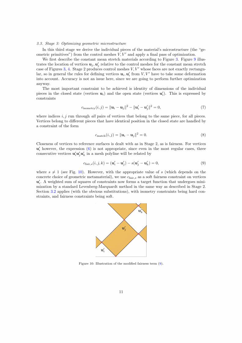
Closeness of vertices to reference surfaces is dealt with as in Stage 2, as is fairness. For verticesu′i however, the expression (6) is not appropriate, since even in the most regular cases, three
consecutive vertices u′iu
′ju
′k in a mesh polyline will be related by
cfair,s(i, j, k) = (u′i − u′
j)− s(u′j − u′
k) = 0, (9)
where s 6= 1 (see Fig. 10). However, with the appropriate value of s (which depends on theconcrete choice of geometric metamaterial), we use cfair,s as a soft fairness constraint on verticesu′i. A weighted sum of squares of constraints now forms a target function that undergoes mini-
mization by a standard Levenberg-Marquardt method in the same way as described in Stage 2.Section 3.2 applies (with the obvious substitutions), with isometry constraints being hard con-straints, and fairness constraints being soft.
Figure 10: Illustration of the modified fairness term (9).
11
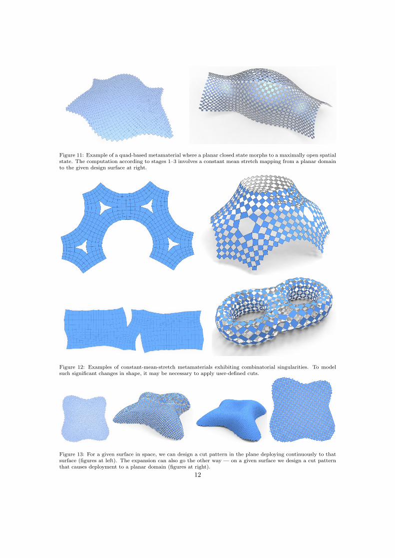
Figure 11: Example of a quad-based metamaterial where a planar closed state morphs to a maximally open spatialstate. The computation according to stages 1–3 involves a constant mean stretch mapping from a planar domainto the given design surface at right.
Figure 12: Examples of constant-mean-stretch metamaterials exhibiting combinatorial singularities. To modelsuch significant changes in shape, it may be necessary to apply user-defined cuts.
Figure 13: For a given surface in space, we can design a cut pattern in the plane deploying continuously to thatsurface (figures at left). The expansion can also go the other way — on a given surface we design a cut patternthat causes deployment to a planar domain (figures at right).
12
3.4. Computations in the bistable case
We here briefly describe in which ways the computations in the bistable case differ.
• Stage 1: The bistable materials of Fig. 5 are capable of representing more arbitrary defor-mations. We could, in theory, use any of the available methods of Geometry Processingto find a deformation of the surface S to the surface S′ that is as rigid as possible up toa scaling factor > 1. In a second step we compute its principal directions (by singularvalue decomposition of its differentials), and use known techniques to find meshes V, V ′
that align with the cross field of principal directions in S resp. S′ [42]. In practice thisprocedure runs into difficulties since it is highly likely that for some pair of correspondingquads we will not be able to fit a configuration according to Fig. 5 to it.
Rather, we adopt a pragmatic approach and use the idea of Fig. 8. The difference to theprevious case is that the principal stretches of the mapping V0 → V ′
0 are computed withEqu. (2). The parameters a, b, A,B, φ needed here are taken from a single model instance.
• Stage 2: For the bistable case, stage 2 is analogous to what is described above: the con-straint csquare defined by Equ. (4) does not occur. Constraint cstretch is modified to fit thestretch factors λ1, λ2 computed by Equ.(2):
cstretch,1(f, f′) = ‖v0 − v2‖2 − λ21‖v′
0 − v′2‖2 = 0,
cstretch,2(f, f′) = ‖v1 − v3‖2 − λ22‖v′
1 − v′3‖2 = 0.
(10)
• Stage 3: Initializing the final pass of optimization is analogous but a bit more complex,since we have to map the rectangular model configuration of Fig. 5 to quadrilaterals thatare rectangular only in an approximate way. This is done by a standard least-squaresapproximation, taking care to match neighbours. As to optimization, we impose isometryconstraints between corresponding pieces analogous to Equ. (7) as hard constraints, weimpose proximity to the reference surface as a soft constraint, and we do not imposefairness.
3.5. Performance of optimization
We exemplarily show how optimization progresses by means of a typical example, namely theone of Fig. 14, bottom. Its control mesh has 2362 vertices, 4614 edges and 2253 faces. Weightscorresponding to soft constraints (proximity to reference and fairness) were set to wprox = wfair =0.01, while weights of hard constraints were set to worth = wgeom = 1. During the 10 iterationswe performed, the fairness and closeness energies behave as follows.
Efair successfully acts as a regularizer. It cannot achieve zero residual (that would only bethe case if mesh polylines are straight). Hard constraints are csquare, cstretch, and corth whosesums of squares yield energies Egeom and Eorth. Their values decrease in the following way:
The total energy thus was reduced from 321.5 to 0.0011 in the last stage of iteration for Stage2 in a total runtime of 1.1 seconds.
Iteration for Stage 3 is analogous. We have energies Eclose as in stage 2, while Efair iscomposed from the fairness constraint of Equ. (9). The weights for soft proximity and fairnessconstraints are set to 0.01. Isometry and matching constraints according to Equ. (7) and (8)are seen as hard constraints and are used to build energies Eisom and Ematch. Those are givenweight 1. The behaviour of these energies over the first 10 iterations is as follows:
The runtime was 5.5 seconds. It can be clearly observed that the fairness energy does notconverge to zero residual. In order to overcome this deficiency we add another 10 iterations,with the weights of soft constraints set to 0. They need an additional 1.7 seconds of runtime andachieve the following values:
For other examples in this paper (Figures 13, 14, 15, and 16) the weights were chosen asdescribed above. The examples are scaled so that the average edge length is 1. On the otherhand the examples of Fig. 12 are scaled such that the bounding box diameter is 1, the weightsof hard constraints are set to 1, while the weights of soft fairness constraints are set to 0.005 andphase out towards zero as the optimization progresses. We did not observe that either of thesetwo regimes performs better than the other one.
4. Results
We performed numerical experiments and actually manufactured several geometric metama-terials to show the capabilities of the two cases treated in this paper.
4.1. Results of numerical optimization
Stages 1–3 as described above can be directly employed to compute a morph between a flatstate and a three-dimensional state, see Figure 11. The procedure still works in the presence ofcombinatorial singularities (see Figure 12), and morphing capabilities are expanded if cuts areapplied.
There are no theoretical restrictions as to the direction of the morph — opening a cut patterncan transform a 2D domain to a 3D surface and also vice versa (Fig. 13).
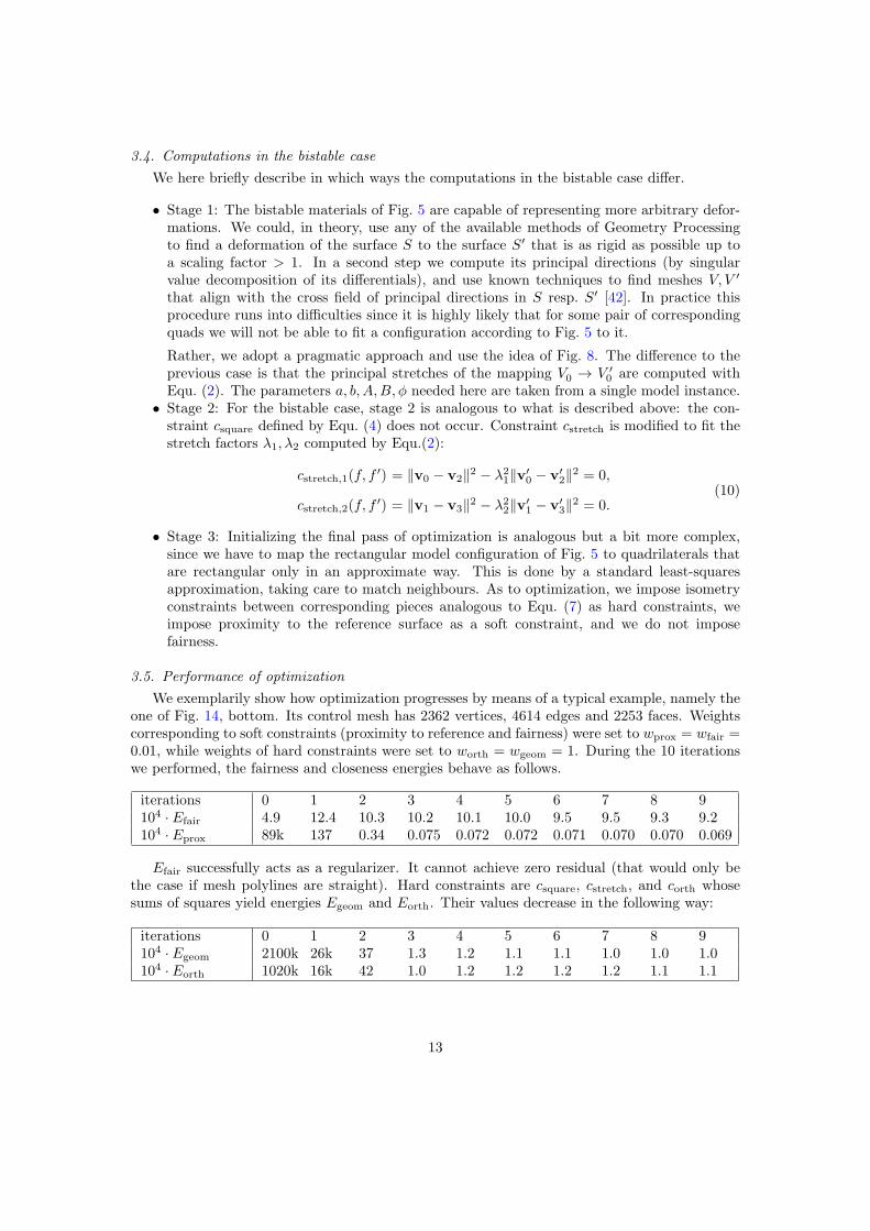
Shape morphs between a curved and a flat state may be more relevant for applications, butwe also applied the procedure to mappings from one double-curved surface to another. Figure 14shows two examples.
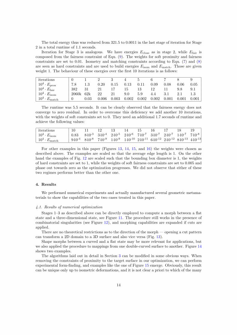
The algorithms laid out in detail in Section 3 can be modified in some obvious ways. Whenremoving the constraints of proximity to the target surface in our optimization, we can performexperimental form-finding, and examples like the one of Figure 15 emerge. Obviously, this resultcan be unique only up to isometric deformations, and it is not clear a priori to which of the many
14
Figure 14: Here we designed a mechanical metamaterial which morphs a double-curved surface (a paraboloid) toa given target surface. The example at the top is the surface of the roof of the Islamic Arts exhibition in theLouvre, Paris.
Figure 15: Form-finding. Here a cut pattern has been drawn on a given surface. When it opens fully, the exampleat right emerges. The computation uses the procedures of §3, but without the constraint that the result has tobe close to a given target surface.
possible isometric solutions the optimization converges. It would not be difficult to combine ouroptimization with user-guided isometries, as recently proposed by [43].
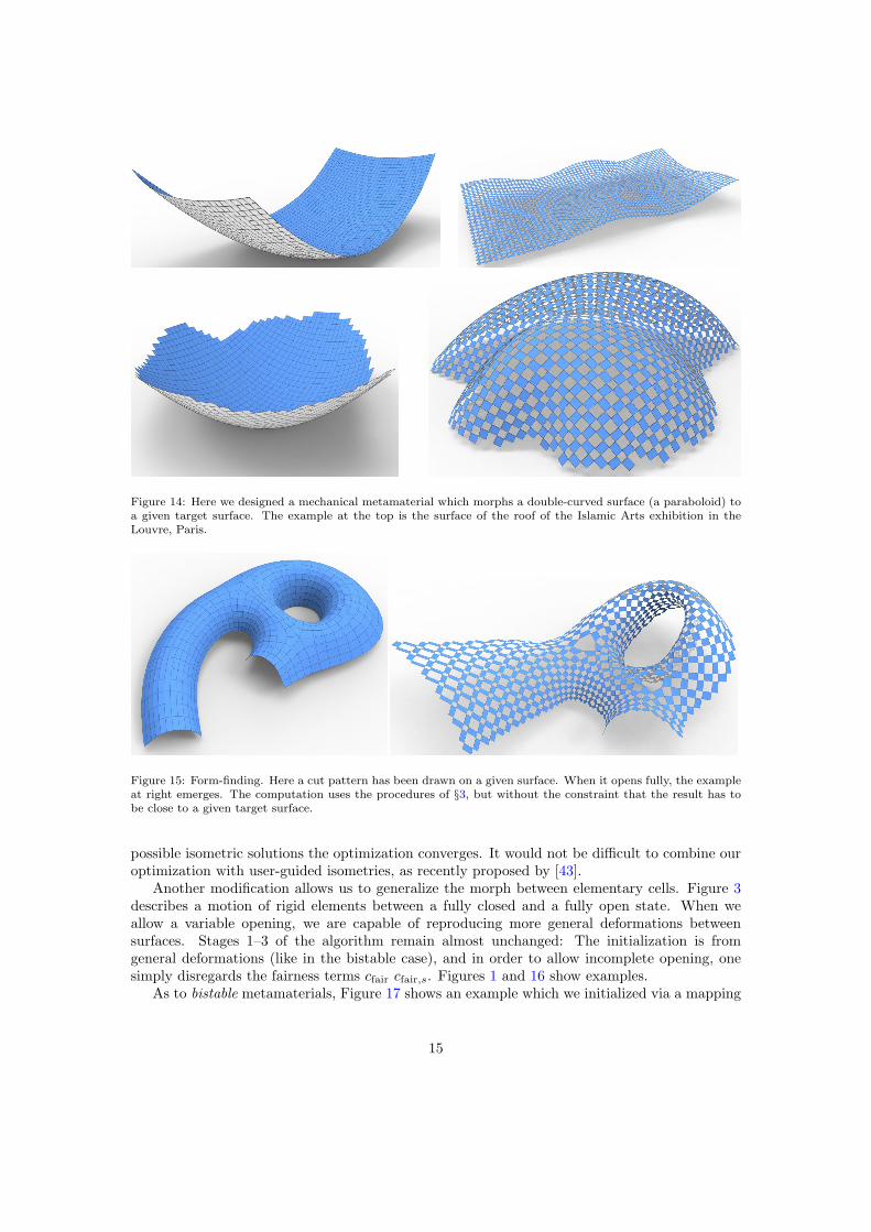
Another modification allows us to generalize the morph between elementary cells. Figure 3describes a motion of rigid elements between a fully closed and a fully open state. When weallow a variable opening, we are capable of reproducing more general deformations betweensurfaces. Stages 1–3 of the algorithm remain almost unchanged: The initialization is fromgeneral deformations (like in the bistable case), and in order to allow incomplete opening, onesimply disregards the fairness terms cfair cfair,s. Figures 1 and 16 show examples.
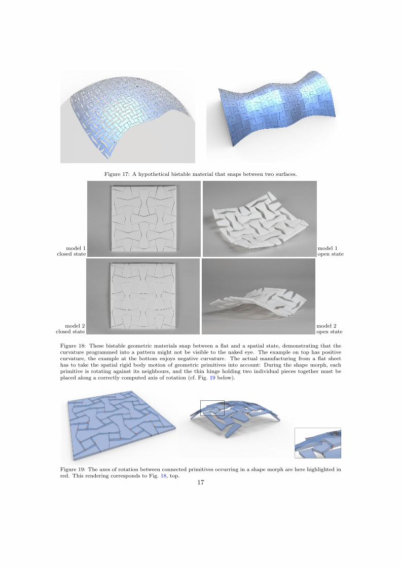
As to bistable metamaterials, Figure 17 shows an example which we initialized via a mapping
15
Figure 16: These examples show the capabilities of quad-based cut patterns that are similar to the constant-mean-stretch case, but exhibit a variable degree of expansion depending on the location.
from a sphere to a target surface.So far we have treated the rigid constituent elements of geometric metamaterials as two-
dimensional objects. This can be the case only approximately. In fact the two examples ofFigure 18 show that three-dimensional effects can be quite noticeable and must not be summarilyneglected. For each individual rigid member Mj our optimization yields an initial position anda final position which arises from the initial position by applying a rotation matrix Aj and atranslation. If piecesMj , Mk are connected, their relative movement is described by the rotationmatrix A−1
j Ak or A−1k Aj , depending on which piece is the observer. The axis of either of these
two relative rotations indicates the direction of the hinge that can exist between pieces Mj ,Mk.Hinges computed in this way are visualized by Fig. 19. We return to the topic of hinges below,in our discussion on fabrication.
4.2. Fabrication
We experimentally confirm the viability of the proposed geometric metamaterials by buildingmodels a person can handle with their hands — see videos
• https://vimeo.com/524221493/b7d951751c (corresponding to Fig. 2),
Figure 17: A hypothetical bistable material that snaps between two surfaces.
model 1closed state
model 1open state
model 2closed state
model 2open state
Figure 18: These bistable geometric materials snap between a flat and a spatial state, demonstrating that thecurvature programmed into a pattern might not be visible to the naked eye. The example on top has positivecurvature, the example at the bottom enjoys negative curvature. The actual manufacturing from a flat sheethas to take the spatial rigid body motion of geometric primitives into account: During the shape morph, eachprimitive is rotating against its neighbours, and the thin hinge holding two individual pieces together must beplaced along a correctly computed axis of rotation (cf. Fig. 19 below).
Figure 19: The axes of rotation between connected primitives occurring in a shape morph are here highlighted inred. This rendering corresponds to Fig. 18, top.
17
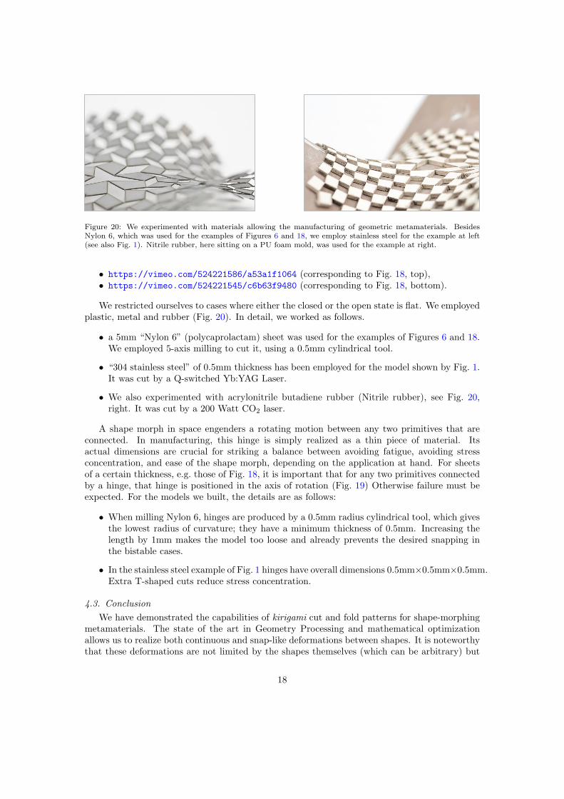
Figure 20: We experimented with materials allowing the manufacturing of geometric metamaterials. BesidesNylon 6, which was used for the examples of Figures 6 and 18, we employ stainless steel for the example at left(see also Fig. 1). Nitrile rubber, here sitting on a PU foam mold, was used for the example at right.
• https://vimeo.com/524221586/a53a1f1064 (corresponding to Fig. 18, top),• https://vimeo.com/524221545/c6b63f9480 (corresponding to Fig. 18, bottom).
We restricted ourselves to cases where either the closed or the open state is flat. We employedplastic, metal and rubber (Fig. 20). In detail, we worked as follows.
• a 5mm “Nylon 6” (polycaprolactam) sheet was used for the examples of Figures 6 and 18.We employed 5-axis milling to cut it, using a 0.5mm cylindrical tool.
• “304 stainless steel” of 0.5mm thickness has been employed for the model shown by Fig. 1.It was cut by a Q-switched Yb:YAG Laser.
• We also experimented with acrylonitrile butadiene rubber (Nitrile rubber), see Fig. 20,right. It was cut by a 200 Watt CO2 laser.
A shape morph in space engenders a rotating motion between any two primitives that areconnected. In manufacturing, this hinge is simply realized as a thin piece of material. Itsactual dimensions are crucial for striking a balance between avoiding fatigue, avoiding stressconcentration, and ease of the shape morph, depending on the application at hand. For sheetsof a certain thickness, e.g. those of Fig. 18, it is important that for any two primitives connectedby a hinge, that hinge is positioned in the axis of rotation (Fig. 19) Otherwise failure must beexpected. For the models we built, the details are as follows:
• When milling Nylon 6, hinges are produced by a 0.5mm radius cylindrical tool, which givesthe lowest radius of curvature; they have a minimum thickness of 0.5mm. Increasing thelength by 1mm makes the model too loose and already prevents the desired snapping inthe bistable cases.
• In the stainless steel example of Fig. 1 hinges have overall dimensions 0.5mm×0.5mm×0.5mm.Extra T-shaped cuts reduce stress concentration.
4.3. Conclusion
We have demonstrated the capabilities of kirigami cut and fold patterns for shape-morphingmetamaterials. The state of the art in Geometry Processing and mathematical optimizationallows us to realize both continuous and snap-like deformations between shapes. It is noteworthythat these deformations are not limited by the shapes themselves (which can be arbitrary) but
by their maximum and minimum principal stretches. In particular our method enables theprogramming of curvature into almost-regular flat patterns. Our method is based on mappingsbetween surfaces (shape morphs). In the process of optimization, this mapping emerges, andelementary material cells align with its principal stretch directions.
A limitation of our work is the need to find a deformation whose principal stretches lie between1 and the allowable maximum. In our implementation we did not make full use of previous work,e.g. [39, 44].
Future work includes a thorough differential-geometric analysis of the questions mentionedin §2.3. On the practical side, it would not be difficult to implement a more explicit relation-ship between mappings on the one hand, and metamaterials on the other hand. This wouldrequire remeshing along principal stretch directions and is treated e.g. by [45]. Future workalso includes extending the capabilities of our limited implementation, e.g. regarding mappingsbetween surfaces which respect their boundaries.
Acknowledgments
This work was supported by the Austrian Science Fund via grants I2978 (SFB-Transregioprogramme Discretization in geometry and dynamics), F77 (SFB grant Advanced ComputationalDesign); further by the Vienna Science and Technology Fund (WWTF) under grant ICT15-082.C. Jiang, F. Rist, and H. Wang were supported by KAUST baseline funding.
References
[1] Z. Wei, Z. V. Guo, L. Dudte, H. Liang, L. Mahadevan, Geometric mechanics of periodicpleated origami, Phys. Rev. Lett. 110 (2013) 215501:1–5.
[2] L. H. Dudte, E. Vouga, T. Tachi, L. Mahadevan, Programming curvature using origamitessellations, Nature Materials 15 (2016) 583–588.
[3] S. M. Felton, M. T. Tolley, B. Shin, C. D. Onal, E. D. Demaine, D. Rus, R. J. Wood,Self-folding with shape memory composites, Soft Matter 9 (2013) 7688–7694.
[4] T. Tachi, Generalization of rigid foldable quadrilateral mesh origami, in: Proc. IASS Sym-posium, U Politecnica Valencia, 2009, pp. 2287–2294.
[5] C. D. Santangelo, Extreme mechanics: Self-folding origami, Ann. Rev. Condensed MatterPhys. 8 (2016) 165–183.
[6] T. Mukhopadhyay, J. Ma, H. Feng, D. Hou, J. M. Gattas, Y. Chen, Z. You, Programmablestiffness and shape modulation in origami materials: emergence of a distant actuation fea-ture, Appl. Mater. Today 19 (2020) 100537:1–7.
[7] A. Islam, H. N. Hansen, P. T. Tang, J. Sun, Process chains for the manufacturing of moldedinterconnect devices, Int J. Adv. Manuf. Technol. 42 (2009) 831–841.
[8] J. T. Karras, C. L. Fuller, K. C. Carpenter, A. Buscicchio, D. McKeeby, C. J. Norman, C. E.Parcheta, I. Davydychev, R. S. Fearing, Pop-up Mars rover with textile-enhanced rigid-flexPCB body, in: IEEE Int. Conf. Robotics & Automation, 2017, pp. 5459–5466.
[9] J. Grima, K. Evans, Auxetic behavior from rotating squares, J. Mat. Sc. Lett. 19 (2000)1563–1565.
19
[10] J. Grima, A. Alderson, K. Evans, Auxetic behaviour from rotating rigid units, PhysicaStatus Solidi B 242 (2005) 561–575.
[11] J. Grima, E. Manicaro, D. Attard, Auxetic behaviour from connected different-sized squaresand rectangles, Proc. Royal Soc. A 467 (2011) 439–458.
[12] M. Konakovic, K. Crane, B. Deng, S. Bouaziz, D. Piker, M. Pauly, Beyond developable:Computational design and fabrication with auxetic materials, ACM Trans. Graph. 35 (4)(2016) 89:1–11.
[13] M. Konakovic-Lukovic, J. Panetta, K. Crane, M. Pauly, Rapid deployment of curved surfacesvia programmable auxetics, ACM Trans. Graph. 37 (4) (2018) 106:1–13.
[14] T. Chen, J. Panetta, M. Schnaubelt, M. Pauly, Bistable auxetic surface structures, ACMTrans. Graph. 40 (4) (2021) 39:1–9.
[15] F. Wang, X. Guo, J. Xu, Y. Zhang, C. Q. Chen, Patterning curved three-dimensionalstructures with programmable kirigami designs, J. Appl. Mech. 84 (2017) 061007:1–7.
[16] T. Castle, Y. Cho, X. Gong, E. Jung, D. M. Sussman, S. Yang, R. D. Kamien, Making thecut: Lattice kirigami rules, Phys. Rev. Lett 113 (2014) 245502,1–5.
[17] T. Castle, D. M. Sussman, M. Tanis, R. D. Kamien, Additive lattice kirigami, Sci. Advances2 (2016) e1601258:1–11.
[18] A. Rafsanjani, D. Pasini, Bistable auxetic mechanical metamaterials inspired by ancientgeometric motifs, Extreme Mechanics Lett. 9 (2016) 291–296.
[19] S. Callens, A. Zadpoor, From flat sheets to curved geometries: Origami and kirigami ap-proaches, Mater. Today 21 (2018) 241–264.
[20] G. Choi, L. Dudte, L. Mahadevan, Programming shape using kirigami tessellations, NatureMaterials 18 (2019) 999–1004.
[21] K. E. Evans, Auxetic polymers: a new range of materials, Endeavour 15 (4) (1991) 170–174.
[22] L. Mizzi, E. Salvati, A. Spaggiari, J.-C. Tan, A. M. Korsunsky, Highly stretchable two-dimensional auxetic metamaterial sheets fabricated via direct-laser cutting, Int. J. Mechan-ical Sc. 167 (2020) 105242:1–14.
[23] Y. Tang, Y. Li, Y. Hong, J. Yin, Programmable active kirigami metasheets with morefreedom of actuation, Proc. Nat. Acad. Sci. U.S.A. 116 (2019) 26407–26413.
[24] N. An, A. G. Domel, J. Zhou, A. Rafsanjani, K. Bertoldi, Programmable hierarchicalkirigami, Adv. Functional Mater. 30 (6) (2020) 1906711.
[25] P. Celli, C. Mcmahan, B. Ramirez, A. Bauhofer, C. J. Naify, D. C. Hofmann, B. Audoly,C. Daraio, Shape-morphing architected sheets with non-periodic cut patterns, Soft Matter14 (48) (2018) 9744–9749.
[26] L. Jin, A. E. Forte, B. Deng, A. Rafsanjani, K. Bertoldi, Kirigami-inspired inflatables withprogrammable shapes, Adv. Mater. (2020) 2001863.
[27] A. Rafsanjani, A. Akbarzadeh, D. Pasini, Snapping mechanical metamaterials under tension,Adv. Mater. 27 (2015) 5931–5.
20
[28] C. Jiang, C. Wang, F. Rist, J. Wallner, H. Pottmann, Quad-mesh based isometric mappingsand developable surfaces, ACM Trans. Graph. 39 (4) (2020) 128:1–13.
[29] P. Laskowski, The traditional and modern look at Tissot’s indicatrix, The American Car-tographer 16 (2) (1989) 123–133.
[30] K. Strubecker, Differentialgeometrie: Theorie der Flachenmetrik, Vol. 1179 of SammlungGoschen, De Gruyter, Berlin, 1969.
[31] M. Lai, E. Krempl, D. Ruben, Introduction to Continuum Mechanics, 4th Edition,Butterworth-Heinemann, 2010.
[32] G. K. Batchelor, An Introduction To Fluid Dynamics, Cambridge University Press, 1967.
[33] R. Sauer, Differenzengeometrie, Springer, 1970.
[34] W. Schief, A. Bobenko, T. Hoffmann, On the integrability of infinitesimal and finite defor-mations of polyhedral surfaces, in: A. Bobenko, et al. (Eds.), Discrete differential geometry,Vol. 38 of Oberwolfach Seminars, Springer, 2008, pp. 67–93.
[35] K. Sharifmoghaddam, G. Nawratil, A. Rasoulzadeh, J. Tervooren, Using flexible trapezoidalquad-surfaces for transformable design, in: S. A. Behnejad, et al. (Eds.), Proc. IASS AnnualSymposium 2020/21 and the 7th Int. Conf. on Spatial Structures, 2021.
[36] A. Bobenko, Y. Suris, Discrete differential geometry: Integrable Structure, American Math.Soc., 2009.
[37] C.-H. Peng, C. Jiang, P. Wonka, H. Pottmann, Checkerboard patterns with black rectangles,ACM Trans. Graph. 38 (6) (2019) 171:1–13.
[38] K. Madsen, H. B. Nielsen, O. Tingleff, Methods for non-linear least squares problems, 2ndEdition, Technical Univ. Denmark, 2004.
[39] O. Sorkine, M. Alexa, As-rigid-as-possible surface modeling, in: Proc. Symp. GeometryProcessing, 2007, pp. 109–116.
[40] L. Liu, L. Zhang, Y. Xu, C. Gotsman, S. Gortler, A local/global approach to mesh param-eterization, Comput. Graph. Forum 27 (5) (2008) 1495–1504.
[41] H. Pottmann, Q.-X. Huang, Y.-L. Yang, S.-M. Hu, Geometry and convergence analysis ofalgorithms for registration of 3D shapes, Int. J. Computer Vision 67 (3) (2006) 277–296.
[42] D. Bommes, H. Zimmer, L. Kobbelt, Mixed-integer quadrangulation, ACM Trans. Graph.28 (3) (2009) 77:1–10.
[43] C. Jiang, H. Wang, V. Ceballos Inza, F. Dellinger, F. Rist, J. Wallner, H. Pottmann, Usingisometries for computational design and fabrication, ACM Trans. Graph. 40 (4) (2021)42:1–12.
[44] L. Liu, L. Zhang, Y. Xu, C. Gotsman, S. J. Gortler, A local/global approach to meshparameterization, Computer Graphics Forum 27 (5) (2008) 1495–1504.
[45] C. Jiang, F. Rist, H. Pottmann, J. Wallner, Freeform quad-based kirigami, ACM Trans.Graph. 39 (6) (2020) 209:1–11.