INTRODUCTION Two of the following articles are reprinted from the CORSA COMMUNIQUE, March 1998. The third article is a critique of these articles by Bob Ballew in a letter dated 18 July, 1998. It must be remembered that everyone does things differently. All three are printed here for the infonnatioo contained in all three. With this information, anyone should be able to disassemble a differential, replace the bearings and seals, setup the proper tooth contact, and go!! Of course, it would be advantageous to have a shop manual too, but oot absolutely necessary.
Transcript
INTRODUCTION
Two of the following articles are reprinted from the CORSA COMMUNIQUE, March 1998. The third article is a critique of these articles by Bob Ballew in a letter dated 18 July, 1998. It must be remembered that everyone does things differently. All three are printed here for the infonnatioo contained in all three. With this information, anyone should be able to disassemble a differential, replace the bearings and seals, setup the proper tooth contact, and go!! Of course, it would be advantageous to have a shop manual too, but oot absolutely necessary.
FQr tho .. of you who are do-it-all Corvair mechanics, here are .orne ideas and belp jn se.tting up a differential. It doe.n't matter whethu the differential is built for limited slip. also known as !'osit:acti~. or noL
J want to ackoowledge Sylvan 'Zue,cJJer forhis tutoring and assistance duriog my leami'1l! process of rebuilding end selting up .my dlily driver differential. I rebuilt the differential on my own. but I could not haye set it up properly
.,.,;thout his help lad knowledge. lis a background. I eiperienced an
input shaft Jailure a while blck and )Vhe" I .s,-",ted to repair the failure. found I broken !'ositraction clutch pack carrier in.roy difTBeotiaJ. After receiving I new input abaft from one of our Cor~ vendo~, I replaced the ctiff~ntial ffith I n9n -Po~ spare that I had .• tored with the iotent (If building a new Posl.1r!Is:tion differential.
When I was It.the Great Western Fan Bdt:r9H and ,swap Meet in 1996, I fouod ~ ",new old" Odco early style Positrac·p.on clutch pack comer housing. I purch .. ed newTIrnkeo bearinss locally, dug 9ut .• ilifferential.eal and gasket set, and !!rp<rep ~ .new thfO)V-out bearing shaft .. nd !'nsar.ctioo ~~tch pack. I culled my collection of ctifferential parts for the best posj side gear and pinion shaft I
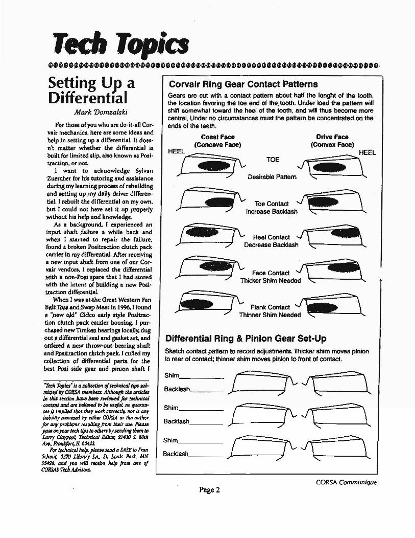
Corvair Ring Gear Contact Patterns Gears are cut with a contact panern about half the lenght 01 the tooth, the location favoring the t09 end 01 the. tooth. Under load the panern will shift somewhat toward the heel 01 the tooth, and will thus become more central. Under no circumstances must the panern be concentrated on the ends 01 the teeth.
Differential Ring & Pinion Gear Set-Up Sketch contact pattern to record adjustments. Thicker shim mOll9s pinion to rear of contact; thinner shim mOll9s pinion to lront 01 contact.
Shim ( ...... r J
\ ~ Backlash / '"
,
Shim ...... ..... ( r J
\ J Backlash .r '" '-
Shim ...... '-\ ( r J\ Backlash
", '" ,
CORSA Communique Page 2
h.d. The originll 3.55 ring .nd pinion g,." were in <xcellent .h.pe. The pinion shaft was i"'pected Ind deemed to be in 'early new condition. That is, the jnter.aI splin .. showed v.ry little (less th.n
5% in !lur vi.w) visible weat I built the diff.rential with the origi
nal shim between the pinion gear and be.ring. thinking that the ring and pinion contoct and bockla.h would b. clo.e for th.t shirn.1 also purth.sed new grade
Definitions
J\!R Backlash .005-.009·
Face { R ....... pnch
Ran~ ~Llne t .
Clearance
The heel of the gear tooth is the large end and the toe Is the small end.
8 bolts for the carrier •••• mbly. When pressing in the new throw·out
b •• ring .h.ft I was car.ful to as.ure th.t one of the notches in the shaft was aligned with the lubric.tion galley in the diffuential cast. This is even more important jf you try using an originaJ shaft with only one notch to mltch up with the lubrication glUey.
After lass.mbled the carrier using the shop manual and h.d pre .. ed the side bearings 0'; the assembly. I could not get the "pumpkin" into the c .... The Cidco cover that I used was just I little too rat. My solution was to pull the b •• ring from the non-Posi side of the pumpkin. in.toU the pumpkin. and press the bearing back on while balancing and holding the ca •• and pumpkin on my press. Tricky but do· able. After consultation with Llrry CI.y· pool and Steve Goodman. I lelrned that this was a unique problem. This was .pparently • very early or slightly thick carrier cover. Larry was very cleat that he has no problem installing the current CidC"u C'.lIrricr.c in the rn!lc with hC"nrin~ on the pumpkin.
Once everything was .... mbled into the spotlessly cle.n and painted c.se. it was time for the setup. When you re.d the shop manuallnd look .t your Corvoir dif· ferential you wiU notice that the orientation of the gear teeth is revened from he.1 to toe. Thia ia because the illustration is puiled from the full siu Chevy manu.1 which. if you remember. is revcrsed from
o Engine Rebuijding 0 Turtlo Rebuilding 0 Cartl Rebuilding 0 Suspension Rebuilding 0 o ~
. ~ .flMfl I. • ·:tJ ~ I ~~ .. :.
~ : Engine Rebuilding Our Specialty i :g All used parts iii .
~ Winter Cleanup Time 20% Off ~ ~ Ask about quantity prices! a c ~ iii reg. \79" ~ ffi Ignitor Electronic Ignition $5995 ~ : Send your ord.r by FAX with your credit card number and expiration da" and we will ~ .E send your order immediately by UPSI Questions? The Right Answersl Contact UI during 0 ~ busin ... hOUri. i 5 larry Shapiro .·mail: ValrPartsOaol.com 3101970·9233 ~ l:! 13224 S. PrairIe Avenue, Hawthorne, CA 90250 FAX 310197~9851 -a ~ Mon.~Frl. 9 AM to 6 PM, Sal 10 AM to 5 PM, Closed Sunday ~ o Complete Service &. Realoradon Dept. 0 Rechrome Bumpe", a Upholslery Kits 0
Page 3
the Corvair because the mgines in OUf
vehicles .re behind the axle. Time for .ome desktop publishing
magic. A little scanning of the Corv.ir shop manua/, I differential setup sheet from GI.ason. Inc., courtesy of Sylvan. .nd presto. we hi ... a graphically accurate COrYsir differential setup des(:ription with contact pattern descriptions and a worksheet to record your s.tup.
A machinist'. bluing compound and • dial indicator are the basic tools needed to .dju.t the shimming .nd set the bocklash for the ring and pinion g.on. I could h .... used feeler gauges for the backlash, but the dial indicator is much more con¥ wnient and leIS prone to the subjective feel of clearance between the gear teeth.
I stort.d with a 0.012" shim on the pinion shan. Ind worked to • final shim Ihickne .. of 0.021" and I backlash. mel' sured with. dial indicator, of 0.003". The contact pattern was center-forward to the toe of the teeth which will allow for maximum life and beat wear on the ring and (lininn gcnrlC.
I suppo .. it would ha ... be.n nice to h.ve the correct GM tools desctibed in the shop manual. like Larry CI.ypool has. but this process does the same job. With patience, a good tutor, some common sen.e, and ordinary mechanic', tools. you can perform a differential setup thlt is textbook perf eeL
The setup and worksheets have been tested by local folks out here in the high desert and work well. They seem 10 make the entire differential rebuild experience even more enjoyable .
After mating the dilTerential to a thoroughly cle.ned trlnsmission. I swopped .... mbli .. on my Ramp.ide. filled the differential and transmiosion. added the whale oil (limited slip treatment). and got back on the road. I am still ple •• ed with the driveabUily. There w ... slight wear-in whine that disappeared after about 35 miles. The transmission and dilTerentill are .till as smooth as sUk. [ am stillamlZed It how much better I can hear the engine with I quiet differential and lranlmission.
Rebuilding a diff.""ntial •• ems to b. a daunting .nd myst.rious challeng ••• wn to Corveir owners who have rebuilt .ngines and other major .ssembUes. The Chevrolet shop manual procedure is filled with obscure and confusing jnstructiona. and seems to flNluire I VIIst
array of sp.ciaUudJ-tools and precision measuring devices_ I beli .... that a simple overhaul can be p.rformed by an amateur mechanic with mode.t tools. That is. if the diff ..... ntial to be r.built is intact and operable, or at worst has one thing wrong with iL If it has suffered c.t.strophic damage. or if you mer.ly have a collection of mism.tch.d parts which y~u want to usembJe. please reconsider. It would be easier. fas~r. and chelper in the long run to put ewrything in a basket and taJce it to an experienced mechanic who h.s done this b.fore. But if you want to I •• rn. by .U means go .head and try.
The advice in this article is not a lub· stitute for the shop manual. it i. a sup' plemerit to iL M with any ""pair job. you should lim study the f.ctory procedures to learn as much .s you can. The shop manual doea contain lome errors and omissiona, but it is an elaentW resource. M for tool.. a well-equipped am.teur m.chanic should have wh.t is n.cessary to dis .... mbl.. r ..... mbl.. and adjult the differential. A parts washer tank would be very us.fullf pinion shims or b.aring raceo must be changed. you will n.ed a hydraulic pr ... and the tools th.t go with iL A dial indicator would be good to have, but is not required.
The most common repair task. on a Corvair differential are r.placement of the throwout b.aring shaft on m.nu.1 Ihift lranaaxl.s. r.p1.c.ment of spider g •• rs. and replacement of. bad bearing. If the failure of a g.ar or b.aring is .ever. .nough that hard .te.l d.bris has circulated through the gears. it may not b. worth r.pairing. On the oth.r hand. many diffs are candidato. for overhaul b.cau .. they are 100 ••• whining. or leu-
ing. Because the removal and install"tion of. differential in a Corvlif is • biS job. t encourage you to make certain your difT is in top condition before installing iL
Next unscrew the side adjuster sleeves. starling wjth the one on the right side (as installed in the car; the starter motor is onl the I.ft sid.~ Chevrol.t made a special
The tricki.st part of the job is setting up the relationship between the ring g •• r and the pinion gtaf. There are several adju.tm.nts .t right angl.s to .ach oth.~ forming a thre.e-dim.nsional puzzle. They are intHactive. which mea"s that making one better may make the other one worse. One adjustment is just the tum of a screw. but the oth.r .djustment requir •• di ..... mbly. pr.ssing off a be.ring. and changing shims. The good n.ws is th.t if your .ssembly is factoryoriginal and no key parts have b •• n chang.d or bldly worn. the setup should not r.quire changing thos. shims. Th. k.y parts you must keep tog.th.r.re the differential clse. the ring and pinion gear set (they .re a marri.d p.ir; you should never mix I ring and a pinion (rom dif· ferent ICU, not even with nn identical p.rt number). the shims b.tween the pinion gear and rear pinion bearing. the throwout b.oring shaft or stator sh.ft, and the rur pinion bearing. Throwout b •• ring shafts should b. manufactured with the same thickn.... so changing that will not disrupt your s.tup. I have been told that roller b.aring .... mbli •• are built to ve.ry tight tolerances •• nd so should b. int.rchangeabl.. but th.t might d.pend on where you buy your bearings.
So now th.t you und.ratand what to expect, let's go ah.ad and r.build your differential.
Th. first step is dis .... mbly. Scrape the major crud off the outside of the cas. so you can g.t wrench.s on all of the bolts. R.move the top cover and drain the fluid into a pan. Undo the locking bolts and tab. on the three big adjusting .I ..... s b.fore you try to tum th.m. On ' an •• rly model or Fe. withdraw the speedometer drive gear .... mbly. On I
I.te mod.l. r.move the axI. yokes by b.nding down the lock tlb. and unscrewing the center bolts; I find a big pip. wrench to be a u&eful tool for holding the yoke while turning the boIL Order new locking tab.. b.c.u.. the on •• you took off are prob.bly rusted. b.nt, .nd tom.
Page 4
tool with four tabs that engage the cast.llated luga .round the edG". but you don't h.yt! to u .. thaL Try I.ying a Corvoir lug wrench handl. or other pry bar across the lug. to tum iL You might wish you had soaked it in pen.tr.ting oil. sine. it may b. yt!ry h.rd to tum. reqUire. many turns to remow. and does not get easier .s you turn iL Resist the urge to shock it 100 .. by hamm.ring on tho .. lugs; they will bro.k off before they move. My .olution w"; to make I tool from a scrap aide adjuster .1...., .nd the biggest socket wrench that fits into the axle hole; I arc-welded the .ocket into the middl •• and now I have I
big tool th.t engages all the luga .nd c.n be driven with in air impact wrench or break.r bat
Once the right .ide adjuster is orr. un~crcw the pinion ~han ndjuAl.cr AiccW'. This is ,;maUer and will come ocr easier. but again you will have to improvise a tool. Now you can withdraw the pinion shaft and put it .. fely •• ide before the ring and pinion gears chip each other while tumbJingaround loose in that case.
R.moving the other sid. adju.t.r .1 ..... m.y not be ••• i.r. but .t lea.t you know how to do iL B.fore you take it out, mark one of them and no~ which .ide it goes on. 10 that you don't mix th.m up I.ter. This il so that the aide b.aring races .nd roll.rs will be k.pt with their mates. You don't need to do this if you are going to repl.c. the sid. b.aring •• and it's not necessary on pg,ilraction axle. becau.e the right side adjuster sl...., ia obviously thinner th.n thel.n.
Now you can remove the ring g.ar carri.r asaernbly through the top of the c .... Thil m.y s •• m like • puul •• 'Ip'cially with Poailraction. but it can be done. Ori.nt the carri.r .... mbly with the ring gear bolts upward • • nd the oppo.ite .ide be.ring pointing downward toward the bottom corner of the c ... which il n •• re.t the starter motor fl.nge. This will place the ring gear diagonally in the top cover opening. Tip on. edge of the ring gear out the top .nd toward the ltarter motor fl.nge .• nd the r •• t of the .... mbly .hould follow. If the
CORSA Communique
widest Plrt of the clrri~r catch~s on the odge of the openiog. and you think you need on~ mor~ fraction of an inch to dear. notice that the side COver assem bly ~as three Imall clearance notches on its odge. Rotate the assembly until one of these face. the COSe odge. then tryag.in.
Once you have the differentialassembty ·pumpkin" out of the c ..... I recommend that you unbolt the ring gear and tlke the clrrier Ip.rt completely to inspect the .pider ge.rs inside. Punch matching marks on th~ two halves of the carrier so that you can reatsemble them in the same orientation.
Further disassembly is optional, depending on what parta you plan 1.0 replace. If the throwout bearing shaft is cracked (a common reason for undertaking this rebuild). pound it out now. If you weren't going 1.0 replace it. in.pect it carefully for hairline cracka at the end. If you have .ny doubta about ita quality. this is the time 1.0 change it. Aftermarket shafts are ~ilable of stronger material, anu some con he fitted WiUl two inPut. sbafts .. ls.
If any bearinp are obviously due for replacement. p.... them oft The shop manual says that removal of the side bear'.g races requires driUing holes in the
eeve 1.0 punch through. but I have always bee, able 1.0 work out the old race by angling a punch through the axle hole and tapping in circles until it faU. out. Of COUl=ae the axJ~ side sraJa must be ~moved first. but you should replace the .. anyway unless they are in excellent shipe.
Cleaning all the parta i. the next step. Se sure you hive removed all O-rings and scraped off any remaining glsk~t material Notice that the spider gu~ and side ge.~ hue washe .. under them which usually stick to one surface or the other; pick them off before they faU off .nd get losL aean all the internal parts in a .. fety solvent until they are .potl .... Don't forget the inside of the pinion gear shalt; a toothbru.h or shotgun bore brush works well. a.aning the caSe i. the biggest part of the job. I use a parts washer tub .nd a stiff bristle brush. and it stiD takes a long time. The outside of the case is usually encrusted with a mixture of road dirt and gear oil. Even if this is not a concoura project. you must elran the exterior or I guarantee the grit will find its way inside during the assembly
process. When you think the case is c1e.n on the inside. dry it and probe the bottom corners and interior casting webs with your fingertip. If it doesn't pass the white glove test. clean it again.
what to usr and where to instan it. but now is the timr to do it.
You can .lso install a dipstick tube using 1964-65 parts; there is • boss on the right side of aU later cases. Of cour ... the car firewall will have to be cut also. At this point I usually do some prep
work on the c .... • Ithough you m.y not be so fussy. If your hands are bleeding from the jagged iron casting nash. you will undentand why I USe a small grinder 1.0 knock down an the sharp edges. This savel more pain later when you are instilling it in the ar. J also chase the thread holes with a bottoming tap. and dre .. the gasket surfaces on the top .nd front with a large nat file. You should use a wire brush or wire wheel to clean the thread. and polish the O-ring lurfaces of the adjuster .1 .... bore •. Lastly. make sure the lubrication f111l1ey 1.0 the rear pinion bearing is dear: there is a gutter which collects spl •• h lube from the meshing ge .... nd a bore which dr.ins it down to the bearins- This bore is hard to inspect, especially if the rear b~aring race has not been rcmoYe<l. but try to prohc it with • wire or nush cleaning solvent through it 1.0 verify th.t there is no obltruction.
If you have a 1964·69 cas. with no drsin plug. think about installing one. I use a magnetic plug which i. the sam. size u the engine oil drain; Chevrolet usod a large pipe plug before 1964. Other tech articles have been written about
From one CorulIlr lover to a.nother ...
Corvair
Embrold~
on * Jackets * Caps * Swe.t Shirts *
* Knit Shirts. etc. * * Most Models Available * Send For Free Literature
Gran4 JUIIdlon. co IJl506 e-mail: Mr.ltInVabitjullo.com
,.,ember of CORSA. PIle .. Pal<, and 1iu:son COl'Da" As.s'"
PageS
When all this is done. clean the C .. e one more time. Paint it if you wish.
Inspection is the next .tep. Look at each part in good light. If you don't know the difference between good and bad bearings and ge.n. take questionable parts to a club meeting. In my exprri· ence. the differenti.1 (spider) gears are usually very stressod. lfthey fail later. you can see how much Jabor will be required to ftx them. At this mom~nt it is pur~Jy a parts cost. so think carefully about replacing them with new. I pr~fer the four·spider gear conversion which is even more reliable. but that i. S200-$3oo in new parts (carrier. gea ... shafts) so many Corvair owners wiJl not consider it .. en though it is weD known as the weakest link in the differential. Four gears orc mandatory for any competition u.e. and highly recommended' for vehicl~s that see heavy load. or increased polW'r, elpecially with manual transmissions.
If the spider gear shaft is worn enough that you can catch your fingornail where the edge of the gear rid ... replace iL Side ge~ are usually sound. but look for spalling or other obvious defects in addi· tion to lerious we~lIr. If equipped with Pasitraction. the clutch plate. may be scratched and heat spottod. If you are in doubt about whether to spend the money for new clutch ... go ahead and assemble the old parts and test the breakaway torque by twi.ting the axles against one anothet Chevrolet says that the Posi ,hould hold 50-100 foot-pound. of torque. The other thing 1.0 watch for with Positraction i. the integrity of the carrier housing itself. The clutch .ide housing tends to fracture into pieces, .. peei.lly on the J 962-64 model ..
The ring and pinion gu ... hould be serviceable unl.ss something broke or the mileage i. very high. but look at them tooth by tooth for chips or damage. While you have the pinion shaft in your hand. look through the tube toward a good light to judge the splines which engage the uansmissjon. Good splines are SO/50 lugs and spaces; if the lugs are
noticeably narfower than the apaces between them. they Ire being pounded away. Failure of th.se spline. would be catastrophic. but r.placement ofth. pinion .hart is a big job. 10 if the .plin .. look marginal get a lecond opinion.
The b.arings should be .ervic.abl. unless the lube wal contaminated with water or chi"" but insp.ct ov.rything. The reaf pinion bearing is the most highly str.ssed becaule the g •• rs h •• t it and thrust against it. If any bearing warranta replacement. that win be the one.
If you have a 1965 car. the axle yak •• have undersize V-joint bolts which are infamous for breakJng. Consider replacing them with the 1966·69 style.
When you have acquired replacement parts for any which failed insp.ction. along with a new s.t of gaskets and .e.I •• you are r •• dy for ·r.assembly. It i ••• s the .aying goes. the revers. of di ..... mbly. Your careful prepar.tion up to this point .hould m.ke it ••• y. )Ult fOllow the Ihnp m8nual, use a torque wrcnch on Lhe ring gear bolts. and remember to wet aU 0-rings and moving parts with 90W g.ar lube. I use a synthetic oil becau.e on. jug of it will last the lif.tim. ofth .... embly. make my good machinery last longer, • av. fu.1 through reduced friction. and .... manual .hifting on cold morninga. Consider it.
The best advice I can give at this stage is to watch your parts inventory, and check off everything on the exploded view before proceeding to the next .tep. It is very frustrating to finish as.embly, dial in your adjustm.nts. and then remember that you forgot to in.taII the . pider gear shaft retaining pin. or the side gear washer •• or the axle nuts. I hate wh.n that happ.ns.
Final a .. embly includ., •• tting the bearing preload. and the gear backlash. The shop manual describe. procedures for this, which most peopl. find very confusing. It also requires j-tools. an inch· pound torque wrench. and a dial indica· tor with .tand. Thes. tools make the adjustments more accurate,.o ule them if you have them. But if you do not. the following procedure will g.t you very close.
To ,et the preload for the pinion bearings. lubricate the pinion b.arings and inatall the pinion shaft into the ca ..
before you install the ring gear carrier. Screw in the pinion bearing adjusting sleeve and tighten it until the pinion .hart i. difficul, to tum by hand. Now looscn it onc notch at a l ime while lurning the pinion sharl with your fingers. Th •• pec for turning torque is 4·6 inch· pound. with us.d b.arings or 9·11 inch· pounds with new be.rings. If you do not have an inch-pound torque wrench. jU8L c.,Limalc. The pinion gcnr is "bout t.hrcC! inches in diameter. 50 if you exert a force of two pounds with your fingers on each side to lurn it. LhaLi six inch-pounds. It should turn .moothly .nd Cr .. ly. neith.r binding up nor rattling laos •. When you are ,s. tisfied with the seUing, mike sure that the locking tab can engage the adjusting sleeve. or move the adjuster slightiy. Mark the position of the .1 .... in the case, then remove the pinion shan.
To .. t the pr.load Cor the side be.rings, lube the bearings .nd in.tall the ring g •• r c.,rricr QA.~mhly in the cn~c. Scn:>W in thC" s ide acJjuftLcr Idccvcs (rcmcmher, yuu m.rked which sid. tiley go l>ock on) by roughly equal .mounts until the ring g.ar is hard to tum. Now loosen one adjuster whil. turning the ring gear with your fm· gers until the turning torque feels correct. o,eck for lock tab alignm.nt. then mark both .id~ .dju,ters.
Remo .. the right sid. adju.ter so that you can move the carrier aside and reinstall the pinion shan and ita: adjuster sleeve. Tighten the pinion bearing adjuster .Ieeve to its m.rk and install the lock tab and bolt. Then re-install the right .ide bearing adjuster .1.... and tighten it down to its mark. Whil. doing this. mike sure that .ome clearance remains between the ring and pinion gears. If they jam together. stop tighten· ing the right.ide adjuster, back it out one or more full tum. to its mark. then tighten the left sid. adju.ter sleeve to its mark. If the side adjulters are tight but there is • Jot of clearance between the g.a ... loosen the left side adju.ter and tighun the right side .djuster by full turns until the gear clearance is minimal. Wh.n you are done. both .id. adjusters should be at th.ir marks, you should not be .bl. to tighten .ith.r side by a full tum. and there should b. some c1.arance between the ring and pinion g.ars.
Page 6
Now you can set the gear b.ckl.sh. Lubricate the ring and pinion gears. and put a 9/16- box wrench on one oCth. riOW gear bolts to turn the .... mbly. Loos.d the len side acJju~Ler by • counted number or notches from itA mark. and tighLen the right sid. adju.ter by the same num· b.r of noteh .. from its mark. This pre· ~r""s the side bearingprelood which you •• t up, while moving the ring R.ar toWlrd llle pinion Rcar. RuloLc the rin~ RCnr hack ond fortil. f •• ling the backl~.h . Keep moving the .ide adjust .... alway. by equal amounts. until the backl.~h
reaches zero. At this point there will be no back-and-rorth play in the gears. Ind you will.tart to Ce.l.n invea.ed ./Tort in turning the ring gear. The backla.h specification il .003"-.OUr. pm.rably in til' middl. of that range. One full notch on the adju.ting II.." .. is .003". so loosen the riRht sid. adju.ter hy t.wo nnteh .. .nd tighten the left .id. adjuster by two l1ol.cht'1l. 111cre Ahnuld he II ~Ji~hL mu.le hCLwt.ocll Lhe t::cllr~ nnw. If you Imyc u feeler gauge around .005", Ule it to dlcck the gap. Tum the ring gear through 8 full rotation to check for d.fects or high .pots; it should tum .moothly.
If pOMibl •• check your work by mork· • ing the ge.r .ngag.m.nt pattern. Thfl accompanying article and workaheeta can help uplain this procedur •. Th. p.ttern may indicate that JIOU should adjult the backlash. th.n check the pattern again. A word of comfort abouts •• r patt.m.: in my .xperi.nce. they .eldom look e .. cUy Iik. the pictures. Th. impor· tant thing i. that the engagement i. fairly centert'd. and don not run off the ends of the teeth. If making on •• id. b.tter makes the other side worse, remember that the drive sid. (the side of the ring g.ar you push on to m.ke the axl. roll forward) carries a bigger load more of the time, so favor the drive side ir you have to compromise.
Finish the .... mbly by in.talling locking tab. and bolts on the sid. adjuster Ii ...... plus speedomet.r drive (early model.). axle yokes (lat. mod.I.) •• nd top cover; Don't forget to fill it with lubricant alter it i. in.talled.
CORSA Communique
PRE LOADING DIFFERENTIAL BEARINGS WHY???
16 July 1998 by Bob Ballew
Lets start with a procedure just about everybody in CORSA is familiar with, such as torquing down a Cylinder Head. Let us suppose you have a copy of an article written by a fellow CORSA member describing engine rebuilding and you get to the part of torquing the Head. He writes in the torque numbers required but describes the way to do it as, "Tighten up the nuts until the torque feels correct". TORQUE FEELS CORRECT?? As most everyone knows, the Head torque has to be absolutely right on the numbers using a torque wrench; too much, pulled studs; too little, blown gaskets!! This would make one wonder about the rest of the information in the article.
Some time back there was article in the Communique about freshening up a Differential and during the procedure for setting up the bearing Preload by hand the instructions were, "until the turning torque feels .correct". FEELS CORRECT???
Most of the articles on the Differential the last few years are quite ·cavalier about this bearing Preloading to the point of almost ignoring it all together. Preloading is sort of like putting twelve pounds into a ten pound bag. You pull up the adjusting nuts to the bearings till all end play of the bearings is gone and then tighten the adjusting nuts up another two or three notches to Preload the bearings. In effect you are putting .the bearings in a bind which "causes enough friction to require quite a bit of inch pounds of torque to turn them. Sounds kind of stupid to the unknowing, but it will create a differential that will go one or two hundred thousand miles with ease. There's very few who can explain why.
Before I let the well kept secret out, lets go to another assembly that contains a set of taper roller bearings just like our differential has. The axle shafts of the 1965 Corvair are connected to the rear wheel Spindle Assemblies. These Assemblies like our Differential requires a very complicated adjustment which allows it to go that one or two hundred thousand miles without attention also. Let me quote a couple of lines from the 1965 chassis manual page 4-26. .
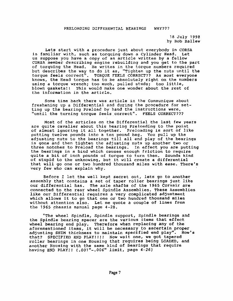
"The wheel Spindle, Spindle support, Spindle bearings and the Spindle bearing spacer are the various items that effect wheel bearing end play. Therefore when replacing any of the aforementioned items, it will be necessary to ascertain proper adjusting SHIM thickness to maintain specified end play". HoW's that? SPECIFIED END PLAY!!!! Now wait one, we got tapered roller bearings in one Housing that requires being LOADED, and another Housing with the same kind of bearings that require having END PLAY!! (.001"-.006" limit, page 4-26)
Page 7
Would you believe there is one thing that causes them to require these two different adjustments. Yep, that's right, and that one thing is HEAT. When you're tooling down the freeway these two Housings (Diff.& Spindle) get unbelievably HOT!I This will cause these Housings to expand more than what is inside. To counter this, we LOAD one and have END PLAY in the other. Now don't shoot, I will explain this seemingly contradiction. The following two rather simplified drawings will show the difference between the construction of the two Assemblies •
....... -- HEAT EXPANSION
SPINDLE
BEARING
F'R.EE PLAY
SPACE1t ~
• HEAT EXPAltSlON
DIFrZREH'rIAI..
IEAltINCS -==I~~..LOADED
You will notice the bearings are installed 180· different from each other. The HEAT will cause one Housing to squeeze the stuff inside, and the other will allow the inside stuff to get quite loose. Now the secret is out. Let's look at it in more detail.
First the difference in the numbers of the adjustments. The numbers for the Differential are from .006" to .009" (that" how much we LOAD the bearings, remember it's two or three of the notches, .003" each) The Spindles END PLAY of it's bearings is only .001"-.006". And of course the reason for the difference in the numbers is because the Differential Housing is much much bigger than the Spindle Housings and will expand about two times more than the relatively smal~ Spindle Housings.
The expansion of the Spindle Housing tries to spread the bearings apart, but they are held together by the shoulder of the Spindle and the Spindle Retaining Nut. But since the bearings were set up with the END PLAY required at the time of assembly, the HEAT expansion of the Housing will just snug up the bearings to take the play out of the Rollers to produce a nice smooth full contact of the .Rollers at freeway speed all day long. without that END PLAY to begin with the Rollers would be squeezed tightly together and bearing failure would be in your future.
The drawing of the Differential Housing shows just the opposite, the expansion of the Housing will create a looseness in the bearings. The Loading of the Bearings at assembly is designed to just UNLOAD the bearing preload at freeway speeds as the Housing expands due to HEAT just to the point where the
PageS
bearings are now just running in a snug mode. It doesn't take a rocket engineer to figure out that if the guy who put the Differential together only snug to begin with, would now at freeway speeds and HEAT, find himself with bearings and gears loose as a goose and pounding themselves to pieces.
How loose would the bearings end up?? Here's a ,test to find out. Put a spare Differential together with the side adjusters and the pinion shaft adjuster all just snug enough to remove all free play from the bearings. Now back out the side adjusting nuts one notch on the left side and one notch on the right side. Now back out the pinion shaft adjusting nut about one and a half notches. What you have done is approximately how much the housing would expand when it reached the HEAT generated at freeway speeds. Now reach in and see how much you can wiggle the pinion shaft and the ring gear assembly. That's how bad the insides of your Differential will be banging around at freeway speeds!!! I predict a short lived set of gears and bearings in your future.
The design engineers know exactly how much the housing will expand at the HEAT of freeway speeds and have gone to a lot of trouble to "tell you how to counteract that with the list of torque readings to come up with the exact amount of bearing PRELOAD to end up with a 200 thousand mile unit!! Now you just go ahead and put your Differential together with the TORQUE SORTA FEELING CORRECT!!!
Don't be stupid, get a 1/4" torque wrench and read the Chassis Manual, after a while it'll make sense. These wrenches are not at the corner market, it takes some hunting around to find them. The torque wrench you need to use on a Differential is a 'Beam' type to be able to measure turning torque. The cute little one that goes "click" won't work, however it's great for oil pans and rocker covers and other small bolts. The 'Beam' type 1/4" torque wrench is shown in use in Fig. 48, page 4-19, in your 1965 Chassis Manual. The catch is, it requires some sort of an adapter to attach it. To solve that problem I have welded 'a 1/4" drive socket onto a spare Governor Drive Gear to use on
, P.G. differential's to measure the turning torque. For three or four speed differential's you need an old spare Mainshaft from the transmission that will fit the splines inside the pinion shaft and weld a 1/4" drive socket to the Mainshaft to measure that Differential's turning torque.
My 1/4" 'Beam' type torque wrench is a DURO/INDESTRO '8091A, made in USA, I ordered it through one of our local auto parts stores here in 29 Palms. If I could get one here, you folks in the big cities should have no trouble. By the way, you can get the 1/4" cute one that "Clicks" from J.e. Whitney for S25.99 for your light work.
I hope I have put the fear of God into you regarding what will happen if you don't pay exact attention to the Preload
Page 9
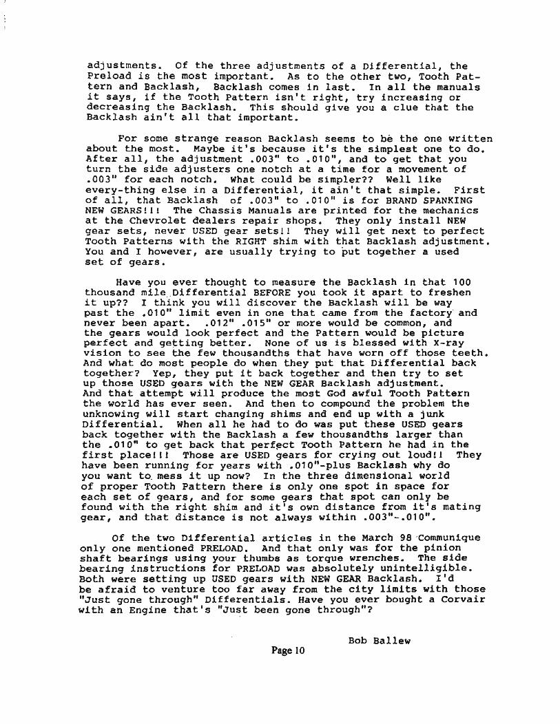
adjustments. Of the three adjustments of a Differential, the Preload is the most important. As to the other two, Tooth Pattern and Backlash, Backlash comes in last. In all the manuals it says, if the Tooth Pattern isn't right, try increasing or decreasing the Backlash. This should give you a clue that the Backlash ain't all that important.
For some strange reason Backlash seems to be the one written about the most. Maybe it's because it's the simplest one to do. After all, the adjustment .003" to .010", and to get that you turn the side adjusters one notch at a time for a movement of .003" for each notch. What could be simpler?? Well like every-thing else in a Differential, it ain't that simple. First of all, that Backlash of .003" to .010" is for BRAND SPANKING NEW GEARS!!! The Chassis Manuals are printed for the mechanics at the Chevrolet dealers repair shops. They only install NEW gear sets, never USED gear sets!! They will get next to perfect Tooth Patterns with the RIGHT shim with that Backlash adjustment. You and I however, are usually trying to put together a used set of gears.
Have you ever thought to measure the Backlash in that 100 thousand mile" Differential BEFORE you took it apart to freshen it up?? I think you will discover the Backlash will be way past the .010" limit even in one that came from the factory ' and never been apart. .012" .015" or more would be common, and the gears would look perfect and the Pattern would be picture perfect and getting better. None of us is blessed with X-ray vision to see the few thousandths that have worn off those teeth. And what do most people do when they put that Differential back together? Yep, they put it back together and then try to set up those USED gears with the NEW GEAR Backlash adjustment. And that attempt will produce the most God awful Tooth Pattern the world has ever seen. And then to compound the problem the unknowing will start changing shims and end up with a junk Differential. When all he had to do was put these USED gears back together with the Backlash a few thousandths larger than the .010" to get back that perf!,!ct Tooth Pattern he had in the first place!!! Those are USED gears for crying out loud!! They have been running for years with .010"-plus Backlash why do
, you want t~ mess it up now? In the three dimensional world of ' proper , Tooth Pattern there is only one spot in space for each set of gears, and for some gears that spot can only be found with the right shim and it's own distance from it's mating gear, and that distance is not always within .003"-.010".
Of the two Differential articles in the March 98 'Communlque only one mentioned PRELOAD. And that only was for the pinion shaft bearings using your thumbs as torque wrenches. The side bearing instructions for PRELOAD was absolutely unintelligible. Both were setting up USED gears with NEW GEAR Backlash. I'd be afraid to venture too far away from the city limits with those "Just gone .through" Differentials. Have you ever bought a Corvair with an Engine that's "Just been gone through"?
Bob Ballew Page 10
ADDENDUM Bob Galli .
It has come to my attention that in the pre,ceding articles, no mention is given specifically to Automatic transm}ssion differentials. One thing that I know that needs attention is the stator shaft. This should be inspected for wear where the converter rides. I try to use a shaft that has no more than .005 wear. I have taken them out that have as much as .010+. Converter seal leaks are possible with this much wear. Also, check for wear inside the stator shaft where the ring seal on the pinion shaft rides, if it catches your fingernail, it is too much. A failed pinion bearing cali cause destruction of this surface.
There are two different slalor shafts, '60·'62, and '63-69. I. '60-'62 stator shafts have I slot on the surface the pinion bearing presses against.
They are also shorter from this surface to the surface that bares against the case, than the '63· '69 stator shaft.
2. '63·'69 stator shafts have six slots on the surface the pinion bearing presses against.
3. Differential cases are machined differently to accept the proper stator shaft, i.e., '60·'62 stator shafts must be used in '60·'62 cases, etc., etc. Pinion setting is impossible in mixed stator shaft/case assemblies. (don't ask me how I know)
4. '60·'61 cases can be identified by code letters beginning with "B", '62·'63 cases can be identified by the code letter "H", '64 cases are obvious by the spring mounting pad underneath.
5. WheJf disassembling '62·'63 differentials, take note which style stator shaft is in it. .
, One other tip I have on differentials, the book shows to remove Ihe carrier bearing races
from· the side adjusting sleeves by drilling a hole to punch them out. I find that if an arc welder is available, a couple of 1 112 inch beads in the center of the race will cause it to shrink when it cools, and it will fall out.
SUBJE<:- DiPltow' RW AXLE HlIIOlt SWING LUBRICATION - 1962 CORVAIl AND CORVAIR "9S" A. I, 62-13
DAn: March lll, 1962.
A del1gn change 11 io process to ra1le the lubricsnt level 5/8" on all 1962 Corvair and Corvair 95 differential carrier asseBblie. aDd threespeed transmissions. Thi. i. being acco.plished by re-locatiog the oil filler plug ' location on these unita. Pour-speed transDission filler plug location vas previously one. inch above the old differential lube level and viII therefore, not require any uodification. . , . Bf.fective 2-19-62 . and· continuing until . 'new parts are available, aaaembly plants are in.talUng 450 Street ''L" exteneion. at the fUler plug "location to 'effectively accomplieh the same reault •• Xn addition to raiaing ' the lube level, all trans-axle a8semblie. are being aotored to 3,000 RPM after initial f111 to "pre-lubricate" tha pinion bearing.
Serial numbers of the first vehicle. incorporating these revisioas .are .as fol1011SI
PUnt 108833 Oakland 138117
St. Loull W111011 Run
109859 207404 .
We request thac you notify all Zone. to be alert for all .eized pinioa bearinge on vehicle. after the abovs .erial .numbers. If any auch failure. are encountered, they should be investigated' in detail for proper 011 level, operating conditions and any other ' pertinent facts. Report. should .be forwarded in the u.ual manner"
If you are personally present prior to the time the repairs are attempted on one of'these failures and are able to in8ure that · 1011 lube level is not the cause, then it would be'desireable to forward the complete rear axle assembly without .it being disassembled. Each of you .hould be alert for one such example. '--- .
TOWING & ROAD SERVICE
B(!)6- ~~~ \~0 dV\ ~ ~ <:.au
~. {4{;O- (CfG). Ct.rAL ~~. d 'I o~/ 63 A:f J~,
.....-__ cx.;r so~.r 4,4Q.-r
(708) 226-1436 (708) 226-1788 FAX
Page 13
Additional change. to be incorporated along with the deaign change to relocate the filler plug include:
1. Piller plug on the 3-apaed tranami .. ion will be changed fr_ 1/2'.0 pipe thread to a 7/8" - 18 plul uling a n)' IOn gaaltat.
2. The filler plug gaaltat common to both 3 and 4-apeed tranaai •• iona. will be red nylon imprinted with a note '~ran •• Fill Only - Check Oil Level at Axle Piller Plul".
3. Rear axle filler plug will be chansed for 1/2" piP. thread to 3/4" pipe threed. .
Extra copiea of thh letter ara being forwarded to . . each Resional Service· Eugi"".r··for dUtribUttOb · to ZofiIl"Ii~I:'tertuil.iiera. .
TlU'ldr:
IlaB . . Jr.:nice1 ~ce Dep . t .. ",t
CCI ·Regional Service Managera .. Pield Service Engineer.
Page 14
Hal you're not going to stick me with that question. Let's iook at another drawing which is in all the manuals and supposed to explain, Heel, Toe, Flank, Face, and Backlash. The drawings are shown with Generic teeth which bear no resemblance to real life Ring Gear teeth. So, for the novice, listen up, The DRIVE (Convex) side is 10· from vertical. The COAST (Concave) side is the slanted side 30· from vertical. (See my drawing on right) On the drawings in the rectangle, I have added dashed lines to show real life ring gear teeth shape. Notice the dashed lines are backwards from my drawing. Reason? Everything in the rectangle is from a Front Eng. car ·with a Ring Gear opposite from CORVAIR.
~~_ 'AC~ I I (.- FLANK
t: .,... PIlCH LINE I 1-'.- .
Cl=A.RA"'C~
THE HEEL OF THE GEA~ TCOOH IS THE LARGE END ANO THE rOE IS i~~ .3MALL END
Rinq qear te~tli froln a f"ll')NT ENGUm c,~ r.
TOE
Or, I should say, since we are the minori ty, WE: are OPPOS I'fr:: all Front Eng. cars. Shown on the bottom of the page is a photo of a CORVAIR Ring Gear, lying teeth up on a bench. Notice COAST surface (White) shows on the left, and DRIVE (White striped) surface shows on the right. Further notice, painted tooth at 6 O'clock is the same shape as my drawing at upper right. Our Ring Gear turns counterclockwise. (What else?) Our pinion gear being behind the axle and at the single painted tooth, and turning counterclockwise as our ·engine, will turn the axle moving our CORVAIR forward. The rest of the world with their pinion gear in front of the axle and ring gear on the drivers side, turns things the other way to go forward. Our problem, we have inherited all their tooth patterns.
COAST surface.-.. showing
!lIGH
LOW
The COR'!AIR Ring Gear shmm flat on ben-:h.
The f"!lONT Eng. Ring Gea= is opposite in ~ !. I details, and turns Clockwise. It is loca ted on the Drivers side of the car.
Page 17
Now the question here is, should the patterns on .Page 2 be reversed qr just the titles be reversed, or both? Who can say with certainty that the patterns on the left is f.or the DRIVE side or the COAST side? Let's add another puzzle; as you look at your Ring Gear on the bench, notice the HEEL (Outer) end ·of the teeth are lower than the TOE (Inner) end. NOw, look at the manuals drawings. They show the HEp-r. (Outer) end as the hiqhest? Puzzling?
Well, the Author of the article in the March, 1998 Communique, came up with his solution to the problem of which side is Drive or Coast, just' reverse the Titles, and since I don't know which of the Manuals Patterns he started out with, I'mOnot sure if he moved the columns of them over also. His drawin9s still show the HEELS higher than the TOES which ain't so in real life. He mention! that Front Eng. cars have their Ring Gears reversed from our Corvairs, that's true. If you have a ring gear from one of them and laid it flat on the bench, next to our CORVAIR rin9 Gear, you would see that the nearest tooth would have the DRIVE side opposit. from our CORVAIR. I mentioned on page 3 that the Rin9 Gear from a Front En9. car is. on the Drivers side, whereas the CORVAIR Ring Gear is on the passenger's side. (I'm goin9 to ask a question and then answer it) Question? Why didn't they put the CORVAIR Ring Gear over there on the Drivers side also?? Since they had to machine an opposite one to move it, why move it?? You would still have the Pinion Gear behind the axle, which would now have an engine that would turn clockwise. (From the rear) It will run just as g?qd that way?? So, Why move the darn Ring Gear over???
Why?? It's because of the crown in the roadll Almost all of our roads are higher in the middle to allow the rain water to run off which requires designers to compensate for that constant leanin9 to the ri9ht. Our little CORVAIRS with most of the weight in the rear are skitterish enough as is, without added wei9ht over on the right with the leanin9. How to move the en9ine wei9ht over to the high side? (Left) Simple, move the Ring Gear over on the Passengers side of the differential and it will allow moving the Engine centerline to the left of the centerline of the Car, One and Three quarters inches!!! !+- this much ~
Of course, in so doing, it requires a Counterclockwise turning Engine. We have to push the back of the Rin9 Gear, UP, to make us go Forward. Elementary Watson!l 1 3/4" doesn't sound like much but we are moving the crankshaft, the P.G., diff. housing, Gen., Starter, Etc., that 1 3/4" further to the left. That results in a hell of a lot of wei9ht 'helping the traction 'of the left rear wheel. They put the battery over there to help also.
On the next page is something I have wanted to do for a long time. Spend a few days changing shims and backlash, and come up with all manner of tooth patterns above and beyond the normal to see just what happens to the patterns. So here are 40 DRIVE tooth patterns for your perusal. Looks like .018" Shim and .00(," Backlash is about · right. Hope to do it again with New Gearso It's possible that New Gears will come up with patterns that look better than the ones I got from these used Gears. Although they didn't look worn, they might of been set up wrong for that short mileage.
Page 18
BACKLASH --~ . '006'"
CORVAIR Real life Patterns
One notch Preload
:1 Pat~erns
Early . 3.55-1 Ring & Pinion showing little
wear.
What you see, is what I got.
SHIM .;:
"1 "'iJ .. . ·,""11 !)
,
Page 19
.009" .012" .015"
Now a word about the size and shape of the Tooth patterns on page 5. I mentioned that I use the Bench Vise position for my Ring Gear tooth pattern work. As I look down into the Diff. case and turn the Drive side of the Ring Gear teeth back to inspect the pattern, what I see is the exact same size, shape and position of the Drive teeth. I can · then draw the pattern more accurately in my true scale tooth outline than if I have to guess just where the pattern would be on a tooth outline a different size or at a different angle, or completely different shape.
Oh, by the way, if you are lucky enough to have the NJ-3289 Holding Fixture or the hole in your bench, and yqu use that positiol for your patterns, you can use these tooth outlines by simply turning them upside down. That is exactly what you will see when you look at your Drive tooth surface, the same size, shape and angle.
Some more interesting things about the patterns on page 5 is the directions the patterns go . According to the information from the book patterns on page 2, changing Shims is supposed to move you to either the Face or the Flank, or visa-versa. However, when 'X added Shims, the pattern went from the HEEL to the TOE, with only a very slight move to the Flank. As far as Backlash goes, the book patterns say, 'Toe Contact, Increase Backlash'. Where I used the thinner Shims, and added Basklash, there wasn't a great deal of movement. However, with the lower group with the thicker Shims, there was quite a bit of movement towards the HEEL, but that was only where the Backlash was up to .012" to .015".
Another interesting result, I have drawn a dashed line with arrows down at an 45° angle from the .015" Shim pattern, those three patterns with different Shims and Backlash, would meet most folks standards, 1f they were the first pattern they ran across. So it's not all cut and dried that there's only one pattern you could come up with. That 45° line runs kinda true for others. '
Now, before we get to the mundane part about setting up a differential, here's an intriguing para. in our books, which most likely drives the novice repairperson up the wall.
RING GEAR AND PINION CONTACT PATTERN
Upon completion of the ring gear.to-pinion backlash adjustment previously described. a check of the gear teeth contact pattern should be made to insure' gea: life and minimite bearing noise from the carrier.
Bad pattern causes pearing noise ??1
1. Thoroughl)· clean the ring g.ar and pinion teeth +-I'll buy tha t. with solvent and air-~y. .
2. Paint rin, gear teeth only with a light and ~ All of them ??? coating 0 a mixture of iron oxide gear marking compound and axle lubricant of a suita,bJe con· sistency to produce a contact pattern on the pinion ~ gear. - - --:- On the WHAT ! I I
3. While firmly holding the pinion v..;th a rag to form a frlction brake, turn the ring gear back and forth ""ith a wrench (Ila, 6C .. S2) on the ring gear mount .. ine bolts until a definite ~ pattern is (ormed on the pinion.
God help us, they said it AGAIN
Page 20
! ! !
4. Inspect the ~ P8tU:rn produced and analvze the results relative to t e following data. Figure 6C-53 provides gear tooth nomenclature and figure 6C-5~ illustrates the varjous contact patterns which may be experienced .. Note; Fig. 6C-54, 60-61 Books
65 book, Fig. 52, page 4-20
Okay, Let's analyze the contact pattern produced on the PINION, just like the last two para. has said. Now we are referred to a drawing-01 RING ~ patternsl Do you get ~feeling that the instructor writing this, hasn't the slightest idea what in the
world he's talking about? At this point the novice most likely will go out and buy a Ford! Or maybe write an article on differential set up.
Of course we old hands of Corvair Manuals, are used to this. We know it's the contact pattern on the Ring Gear Teeth, not the Pinion that we are checking. (Hey, you don't suppose that this clown has got the Pinion Gear mixed up with the Coast side Ring Gear tooth patterns?) (Ya-know, where they show 'Coast Side Patterns' and call it 'Drive Side.') I think this guy that writes in our manuals, is the same guy that translates Japanese motor manuals into English. .
Let's move on to TOOLS. No, let's check out something else in our books. I've got you conditioned to most anything now, so just one last fig. showing getting that contact Pattern on the PINION. I didn't .plan this, really? But I just happen to have that Book Fig. on the upper right on page 1 . So, flip back.
This picture is in all our 60-61-65 Main Books. This is the operation on the bench with a hole in the middle. It's the procedure using a wrench on a bolt head and holding the Pinion Shaft to get a definite pattern on the Pinion Gear Teeth. The person who took the picture, took great pains to add perfect tooth patterns with his air brush on the Ring Gear teeth, and also on the Pinion Gear Teeth. (Shows better in the Books) However, if you look closely the Patterns on the Pinion Teeth are on it's Drive side, but the perfect patterns on the Ring Gear teeth are on the (You guessed it) COAST SIDE. In the picture the Drive Side of the Ring Gear Teeth, are the top three, don't show nothing, only a black shadow all .. cross the surface. You don't suppose that this clown is trying to fool us with these perfect Patterns on the Coast side, to make it appear therefore the Drive side must be perfect too??? Remember the Ring Gear Teeth are supposed to be painted on the Coast side and Drive side also. "Where!s The Paint?" "Where's the Pattern?"