8
INTRODUCTION

INTRODUCTION

Congratulations on your purchase of the Stealth Power Amplifier. The Stealth Power Amplifier was designed to provide a new level of power amplifier performance. The Stealth Power Amplifier is based on both ISP Technologies patented D-CAT (Dynamic Current Amplifier Technology) and the new Dynamic Adaptive Amplifier Technology which is covered under patents pending. The Stealth is designed for use as a dual channel stereo or mono power amplifier to drive your guitar speaker cabinet with a minimum load impedance of 4 ohms in stereo mode and minimum load impedance of 8 ohms in mono bridged mode. The Stealth is powered from an external laptop style switch mode power adaptor. The design provides excellent sonic performance for the guitar rig with excellent clipping characteristics. Please read this manual carefully for a through explanation of the Stealth Power Amplifier and its functions.
IMPORTANT SAFTEY INSTRUCTIONS
Please read the following very carefully before operating this unit
Read ALL instructions carefully before using this unit. Keep these instructions for future reference.
Heed all warnings and follow all instructions.
Do not use this unit near water, in the rain, or where there is moisture. If this warning is ignored a
serious electrical shock or death may occur.
Do not attempt to service this unit. No user serviceable parts inside. Refer servicing to qualified, ISP
approved personnel. Servicing is required when the unit is damaged in any way, such as power
adaptor is damaged, liquid has been spilled into the unit, the unit has been exposed to rain or
moisture, does not operate normally, or has been dropped.
Care should be taken to avoid spilling any foreign objects or liquid into this unit. Avoid exposure of
this equipment to dripping or splashing and ensure that no objects filled with liquid, such as vases,
are placed on the equipment.
Only use accessories or attachments that are specified by the manufacturer.
Failure to follow these instructions may void the warranty.
NO UER SERVICABLE PARTS INSIDE. REFER SERVICING TO
QUALIFIED ISP TECHNOLOGIES SERVICE PERSONNELL.
The lightning bolt triangle is used to alert the user to the risk of electric shock.
The exclamation point triangle is used to alert the user to important operating or
maintenance instructions.
POWER REQUIREMENTS This unit requires the connection of the external AC Power Adaptor to a 120 volt AC outlet. Do not attempt to connect this unit to any power source other than the one supplied with the Stealth Power Amplifier. The Stealth Power Amplifier will typically draw on the order of 2 amps of current off the AC line when in use.
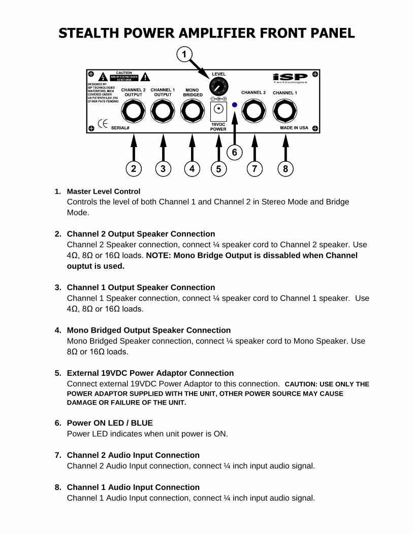
STEALTH POWER AMPLIFIER FRONT PANEL
1. Master Level Control
Controls the level of both Channel 1 and Channel 2 in Stereo Mode and Bridge
Mode.
2. Channel 2 Output Speaker Connection
Channel 2 Speaker connection, connect ¼ speaker cord to Channel 2 speaker. Use
4Ω, 8Ω or 16Ω loads. NOTE: Mono Bridge Output is dissabled when Channel
ouptut is used.
3. Channel 1 Output Speaker Connection
Channel 1 Speaker connection, connect ¼ speaker cord to Channel 1 speaker. Use
4Ω, 8Ω or 16Ω loads.
4. Mono Bridged Output Speaker Connection
Mono Bridged Speaker connection, connect ¼ speaker cord to Mono Speaker. Use
8Ω or 16Ω loads.
5. External 19VDC Power Adaptor Connection
Connect external 19VDC Power Adaptor to this connection. CAUTION: USE ONLY THE
POWER ADAPTOR SUPPLIED WITH THE UNIT, OTHER POWER SOURCE MAY CAUSE
DAMAGE OR FAILURE OF THE UNIT.
6. Power ON LED / BLUE
Power LED indicates when unit power is ON.
7. Channel 2 Audio Input Connection
Channel 2 Audio Input connection, connect ¼ inch input audio signal.
8. Channel 1 Audio Input Connection
Channel 1 Audio Input connection, connect ¼ inch input audio signal.

STEALTH POWER AMPLIFIER TECHNOLOGY
The Stealth Power Amplifier is based on a new Power Amplifier Technology developed by ISP Technologies. The Stealth uses ISP Technologies patented “Dynamic Current Amplifier Technology” (D-CAT) controlled by a new patent pending “Adaptive Dynamic Amplifier Technology” which provides a novel Class H power amplifier topology with improved efficiency and Dynamic Voltage Multiplication. This allows the Stealth Power Amplifier to operate on a low voltage19 volt DC power adaptor and provide extremely high output voltage swing well in excess of the 19 volts DC.
The graph below shows the output voltage waveform and adaptive power supply rails. At low power the Stealth operates as a normal class A-B power amplifier. When the output signal approaches the nominal 19 volt power supply rail the Dynamic Adaptive Amplifier Technology provides two functions, a dynamic multiplication or lifting of the power supply rails and an adaptivly tracking power supply where the power supply rails will continuously track the output signal within a fixed ratio. The net result is a class A-B power amplifier with excellent sonic performance and very musical clipping charecteristics with greatly increased power efficiency and higher output voltage swing.
STEALTH POWER AMPLIFIER OPERATION
The Stealth power amplifer is designed to operate like any other power amplifier with a line level input signal and allow operation in Stereo or Mono Bridge mode. The Stealth amplifier ships with an external switch mode power adaptor, which connects to normal AC power. The supplied Power Adaptor will operate between 100 VAC and 240VAC input and will connect to the Stealth Power connector providing 19VDC @ 7.9 amps output power for the Stealth. Do not attempt to power the Stealth with any other power source than the one supplied from ISP Technologies. On power up, the Stealth will mute all outputs for a Turn On time of approximatly 4 seconds. If power is removed the Stealth will instantly mute the output before any audible pop can occur. Connect the Stealth into your system as shown below for either Stereo or Mono operation. For high power rigs multiple Stealth Power Amplifiers can be used with multiple speakers. NOTE: The minimum load impedance allowed in Stereo Operation is 4 ohms and the minimum allowed load impedance in Mono Bridged mode is 8 ohms. If lower load impedance is used the Stealth will shut down when the demand for current exceeds the maximum allowed in each configuration. If shutdown occurs check your speaker load impedange
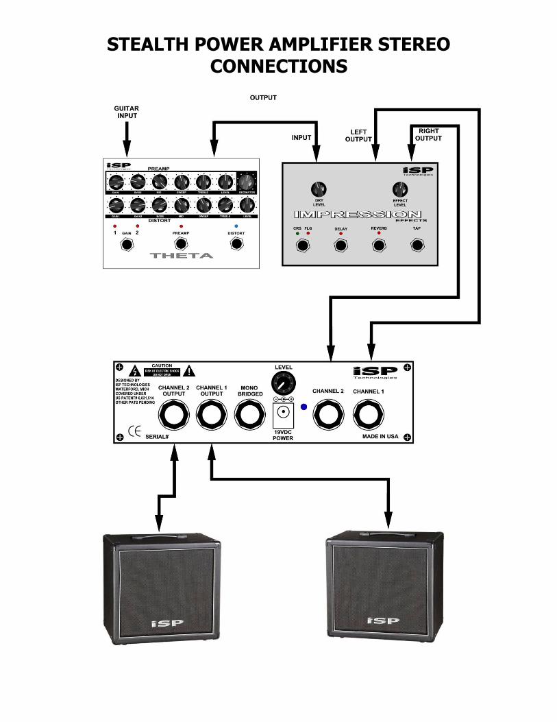
STEALTH POWER AMPLIFIER STEREO CONNECTIONS

STEALTH POWER AMPLIFIER MONO BRIDGED
CONNECTIONS
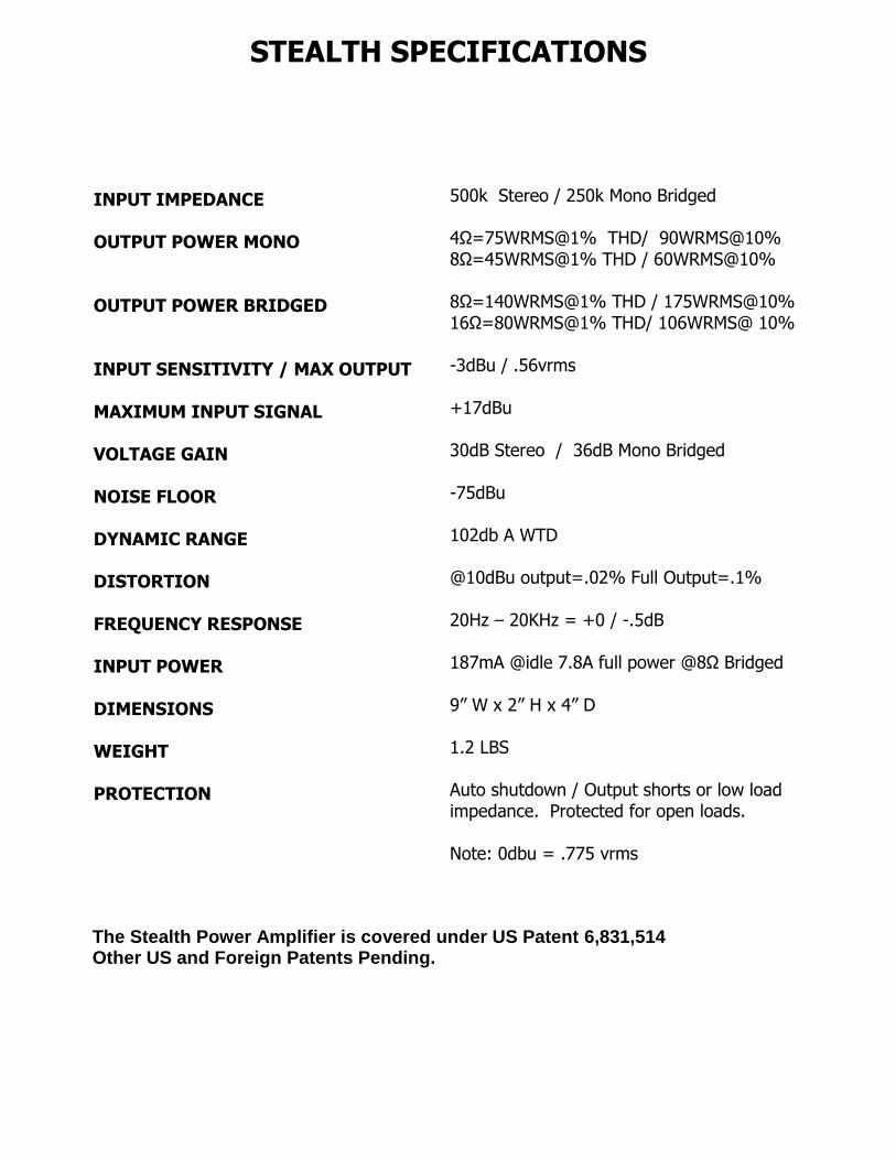
STEALTH SPECIFICATIONS
INPUT IMPEDANCE OUTPUT POWER MONO OUTPUT POWER BRIDGED INPUT SENSITIVITY / MAX OUTPUT MAXIMUM INPUT SIGNAL VOLTAGE GAIN NOISE FLOOR DYNAMIC RANGE DISTORTION FREQUENCY RESPONSE INPUT POWER DIMENSIONS WEIGHT PROTECTION
500k Stereo / 250k Mono Bridged 4Ω=75WRMS@1% THD/ 90WRMS@10% 8Ω=45WRMS@1% THD / 60WRMS@10% 8Ω=140WRMS@1% THD / 175WRMS@10% 16Ω=80WRMS@1% THD/ 106WRMS@ 10% -3dBu / .56vrms +17dBu 30dB Stereo / 36dB Mono Bridged -75dBu 102db A WTD @10dBu output=.02% Full Output=.1% 20Hz – 20KHz = +0 / -.5dB 187mA @idle 7.8A full power @8Ω Bridged 9” W x 2” H x 4” D 1.2 LBS Auto shutdown / Output shorts or low load impedance. Protected for open loads. Note: 0dbu = .775 vrms
The Stealth Power Amplifier is covered under US Patent 6,831,514 Other US and Foreign Patents Pending.

WARRANTY AND SERVICE
The Internal Circuitry is fully guaranteed to be free of defects under normal use and service for a period of three years from the date of purchase. Any damage resulting from the misuse or the failure to follow the precautions and instructions will void the warranty. In the event that the unit needs to be repaired, please return the unit to ISP Technologies directly. Simply repack the unit, send a copy of the original receipt, a note stating the problem, and send it to: ISP Technologies, LLC 5479 Perry Drive Unit B Waterford, MI 48329 Attn: Repair Dept. All shipping charges must be fully prepaid. ISP will not be responsible for any damages incurred in shipping of any unit. Any claim will need to be settled with the shipping company. The warranty will be voided if the serial number has been tampered with in any way. The warranty card must also be filled out and returned in order to activate the warranty. Should you have any questions for the repair department prior to returning the product please call 1-(248)-673-7790
ISP TECHNOLOGIES, LLC 5479 PERRY DRIVE UNIT B WATERFORD, MI. 48329 Phone: 248-673-7790 www.isptechnologies.com


