P1: OTA/XYZ P2: ABC c01 JWBK431/Hsu January 21, 2010 22:18 Printer Name: Yet to Come 1 Introduction 1.1 Overview A reinforced concrete structure may be subjected to four basic types of actions: bending, axial load, shear and torsion. All of these actions can, for the first time, be analyzed and designed by a single unified theory based on the three fundamental principles of mechanics of materials: namely, the stress equilibrium condition, the strain compatibility condition, and the constitutive laws of concrete and steel. Because the compatibility condition is taken into account, this theory can be used to reliably predict the strength of a structure, as well as its load–deformation behavior. Extensive research of shear action in recent years has resulted in the development of various types of truss model theories. The newest theories for shear can now rigorously satisfy the two-dimensional stress equilibrium, Mohr’s two-dimensional circular strain compatibility and the softened biaxial constitutive laws for concrete. In practice, this new information on shear can be used to predict the shear load versus shear deformation histories of reinforced concrete structures, including I-beams, bridge columns and low-rise shear walls. Understanding the interaction of shear and bending is essential to the design of beams, bridge girders, high-rise shear walls, etc. The simultaneous application of shear and biaxial loads on a two-dimensional (2-D) ele- ment produces the important stress state known as ‘membrane stresses’. The 2-D element, also known as ‘membrane element’, represents the basic building block of a large variety of structures made of walls and shells. Such structures, including shear walls, submerged containers, offshore platforms and nuclear containment vessels, can be very large with walls several feet thick. The information in this book provides a rational way to analyze and to design these wall-type and shell-type structures, based on the three fundamental principles of the mechanics of materials for two-dimensional stress and strain states. The simultaneous application of bending and axial load is also an important stress state prevalent in beams, columns, piers, caissons, etc. The design and analysis of these essential structures are presented in a new light, emphasizing the three principles of mechanics of materials for the parallel stress state, i.e. parallel stress equilibrium, the Bernoulli linear strain compatibility and the uniaxial constitutive laws of materials. Unified Theory of Concrete Structures Thomas Hsu and Yi-Lung Mo C 2010 John Wiley & Sons, Ltd 1 COPYRIGHTED MATERIAL
Transcript
P1: OTA/XYZ P2: ABCc01 JWBK431/Hsu January 21, 2010 22:18 Printer Name: Yet to Come
1Introduction
1.1 Overview
A reinforced concrete structure may be subjected to four basic types of actions: bending,axial load, shear and torsion. All of these actions can, for the first time, be analyzed anddesigned by a single unified theory based on the three fundamental principles of mechanicsof materials: namely, the stress equilibrium condition, the strain compatibility condition, andthe constitutive laws of concrete and steel. Because the compatibility condition is taken intoaccount, this theory can be used to reliably predict the strength of a structure, as well as itsload–deformation behavior.
Extensive research of shear action in recent years has resulted in the development of varioustypes of truss model theories. The newest theories for shear can now rigorously satisfy thetwo-dimensional stress equilibrium, Mohr’s two-dimensional circular strain compatibility andthe softened biaxial constitutive laws for concrete. In practice, this new information on shearcan be used to predict the shear load versus shear deformation histories of reinforced concretestructures, including I-beams, bridge columns and low-rise shear walls. Understanding theinteraction of shear and bending is essential to the design of beams, bridge girders, high-riseshear walls, etc.
The simultaneous application of shear and biaxial loads on a two-dimensional (2-D) ele-ment produces the important stress state known as ‘membrane stresses’. The 2-D element,also known as ‘membrane element’, represents the basic building block of a large varietyof structures made of walls and shells. Such structures, including shear walls, submergedcontainers, offshore platforms and nuclear containment vessels, can be very large with wallsseveral feet thick. The information in this book provides a rational way to analyze and todesign these wall-type and shell-type structures, based on the three fundamental principles ofthe mechanics of materials for two-dimensional stress and strain states.
The simultaneous application of bending and axial load is also an important stress stateprevalent in beams, columns, piers, caissons, etc. The design and analysis of these essentialstructures are presented in a new light, emphasizing the three principles of mechanics ofmaterials for the parallel stress state, i.e. parallel stress equilibrium, the Bernoulli linear straincompatibility and the uniaxial constitutive laws of materials.
P1: OTA/XYZ P2: ABCc01 JWBK431/Hsu January 21, 2010 22:18 Printer Name: Yet to Come
2 Unified Theory of Concrete Structures
The three-dimensional (3-D) stress state of a member subjected to torsion must take intoaccount the 2-D shear action in the shear flow zone, as well as the bending action of the concretestruts caused by the warping of the shear flow zone. Since both the 2-D shear action and thebending action can be taken care of by the simultaneous applications of Mohr’s compatibilitycondition and Bernoulli’s compatibility condition, the torsional action becomes, for the firsttime, solvable in a scientific way. This book provides all the necessary information leading upto the rational solution of the problem in torsion.
Because each of the four basic actions experienced by reinforced concrete structures hasbeen found to adhere to the fundamental principles of the mechanics of materials, a unifiedtheory is developed encompassing bending, axial load, shear and torsion in reinforced as wellas prestressed concrete structures. This book is devoted to a systematic integration of all theindividual theories for the various stress states. As a result of this synthesis, the new rationaltheories should replace the many empirical formulas currently in use for shear, torsion andmembrane stress.
The unified theory is divided into six model components based on the fundamental principlesemployed and the degree of adherence to the rigorous principles of mechanics of materials. Thesix models are: (1) the struts-and-ties model; (2) the equilibrium (plasticity) truss model; (3) theBernoulli compatibility truss model; (4) the Mohr compatibility truss model; (5) the softenedtruss model; and (6) the softened membrane model. In this book the six models are presentedas rational tools for the solution of the four basic actions: bending, axial load, and particularly,2-D shear and 3-D torsion. Both the four basic actions and the six model components ofunified theory are presented in a systematic manner, focusing on the significance of theirintrinsic consistencies and their inter-relationships. Because of its inherent rationality, thisunified theory of reinforced concrete can serve as the basis for the formulation of a universaland international design code.
In Section 1.2, the position of the unified theory in the field of structural engineeringis presented. Then the six components of the unified theory are introduced and defined inSection 1.3, including a historical review of the six model components, and an explanation ofhow the book’s chapters are organized. The conceptual introduction of the first model – thestruts-and-ties model – is given in Section 1.4. Detailed study of the struts-and-ties model isnot included in this book, but is available in many other textbooks on reinforced concrete.
Chapters 2–7 present a systematic and rigorous study of the last five model components ofthe unified theory, as rational tools to solve the four basic actions (bending, axial load, shear andtorsion) in concrete structures. The last three chapters, 8–10, illustrate the wide applications ofthe unified theory to prestressed I-beams, ductile frames, various types of framed shear walls,bridge columns, etc., subjected to static, reversed cyclic, dynamic and earthquake loadings.
1.2 Structural Engineering
1.2.1 Structural Analysis
We will now look at the structural engineering of a typical reinforced concrete structure, andwill use, for our example, a typical frame-type structure for a manufacturing plant, as shown inFigure 1.1. The main portal frame, with its high ceiling, accommodates the processing work.The columns have protruding corbels to support an overhead crane. The space on the right,
P1: OTA/XYZ P2: ABCc01 JWBK431/Hsu January 21, 2010 22:18 Printer Name: Yet to Come
Introduction 3
Figure 1.1 A typical frametype reinforced concrete structure
with the low ceiling, serves as offices. The roof beams of the office are supported by spandrelbeams which, in turn, are supported by corbels on the left and columns on the right.
The structure in Figure 1.1 is subjected to all four types of basic actions – bending M, axialload N, shear V and torsion T . The columns are subjected to bending and axial load, while thebeams are under bending and shear. The spandrel beam carries torsional moment in additionto bending moment and shear force. Torsion frequently occurs in edge beams where the loadsare transferred to the beams from one side only. The magnitudes of these four actions areobtained by performing a frame analysis under specified loads. The analysis can be based oneither the linear or the nonlinear material laws, and the cross-sections can either be uncrackedor cracked. In this way, the four M, N, V and T diagrams are obtained for the whole structure.This process is known as ‘structural analysis’.
Table 1.1 illustrates a four-step general scheme in the structural engineering of a reinforcedconcrete structure. The process of structural analysis is the first step as indicated in row 1of the table. While this book will not cover structural analysis in details, information on thistopics can be found in many standard textbooks on this subject.
1.2.2 Main Regions vs Local Regions
The second step in the structural engineering of a reinforced concrete structure is to recognizethe two types of regions in the structure, namely, the ‘main regions’ and the ‘local regions’. Thelocal regions are indicated by the shaded areas in Figure 1.1. They include the ends of a columnor a beam, the connections between a beam and a column, the corbels, the region adjacent to aconcentrated load, etc. The large unshaded areas, which include the primary portions of eachmember away from the local regions are called the main regions.
P1: OTA/XYZ P2: ABCc01 JWBK431/Hsu January 21, 2010 22:18 Printer Name: Yet to Come
4 Unified Theory of Concrete Structures
Tabl
e1.
1U
nifie
dth
eory
ofre
info
rced
conc
rete
stru
ctur
es
P1: OTA/XYZ P2: ABCc01 JWBK431/Hsu January 21, 2010 22:18 Printer Name: Yet to Come
Introduction 5
From a scientific point of view, a main region is one where the stresses and strains aredistributed so regularly that they can be easily expressed mathematically. That is, the stressesand strains in the main regions are governed by simple equilibrium and compatibility con-ditions. For columns that are under bending and axial load, the equilibrium equations comefrom the parallel force equilibrium condition, while the compatibility equations are governedby Bernoulli’s hypothesis of the plane section remaining plane. In the case where beams aresubjected to shear and torsion, the stresses and strains should satisfy the two-dimensionalequilibrium and compatibility conditions, i.e. Mohr’s stress and strain circles.
In contrast, a local region is one where the stresses and strains are so disturbed and irregularthat they are not amenable to mathematical solution. In particular, the compatibility conditionsare difficult to apply. In the design of the local regions the stresses are usually determinedby equilibrium condition alone, while the strain conditions are neglected. Numerical analysisby computer (such as the finite element method), can possibly determine the stress and straindistributions in the local regions, but it is seldom employed due to its complexity.
The local region is often referred to as the ‘D region’. The prefix D indicates that the stressesand strains in the region are disturbed or that the region is discontinuous. Analogously, themain region is often called the ‘B region’, noting that the strain condition in this bending regionsatisfies Bernoulli’s compatibility condition. This terminology does not take into account thestrain conditions of structures subjected to shear and torsion, which should satisfy Mohr’scompatibility condition. Therefore, the term ‘B–M region’ would be more general and tech-nically more accurate, including both the Bernoulli and the Mohr compatibility conditions.However, since the term ‘B region’ has been used for a long time, it could be thought of as asimplification of the term ‘B–M region’.
The second step of structural engineering is the division of the main regions and localregions in a structure as indicated in row 2 of Table 1.1. On the one hand, the main regionsof a structure are designed directly by the four sectional actions, M, N, V and T , according tothe four sectional action diagrams obtained from structural analysis. On the other hand, thelocal regions are designed by stresses acting on the boundaries of the regions. These boundarystresses are calculated from the four action diagrams at the boundary sections. A local regionis actually treated as an isolated free body subjected to external boundary stresses.
The third step of structural engineering is the determination of the design actions for thetwo regions. This third step of finding the sectional actions for main regions and the boundarystresses for local regions is indicated in row 3 of Table 1.1. Once the diagrams of the fouractions are determined by structural analysis and the two regions are identified, all the mainregions and local regions can be designed.
1.2.3 Member and Joint Design
This fourth step of structural engineering is commonly known as the member and joint design.More precisely, it means the design and analysis of the main and local regions. By this processthe size and the reinforcement of the members as well as the arrangement of reinforcement inthe joints are determined.
The unified theory aims to provide this fourth and most important step with a rationalmethod of design and analysis for all of the main and local regions in a typical reinforcedconcrete structure, such as the one in Figure 1.1. It serves to synthesize all the rational theoriesand to replace all the empirical design formulas for these regions.
P1: OTA/XYZ P2: ABCc01 JWBK431/Hsu January 21, 2010 22:18 Printer Name: Yet to Come
6 Unified Theory of Concrete Structures
The position of the unified theory in the scheme of structural engineering is shown in row4 of Table 1.1. The six model components of the unified theory are distinguished by theiradherence to the three fundamental principles of the mechanics of materials (the equilibriumcondition, the compatibility condition and the constitutive laws of materials). The six modelsare named to reflect the most significant principle(s) embodied in each as listed in thefollowing section.
1.3 Six Component Models of the Unified Theory
1.3.1 Principles and Applications of the Six Models
As shown in Table 1.1, some of the six models are intended for the main regions and some forthe local regions. Others may be particularly suitable for the service load stage or the ultimateload stage. The six models are summarized below, together with their basic principles and thescope of their applications:
1.3.1.1 Struts-and-ties Model
Principles: Equilibrium condition onlyApplications: Design of local regions
1.3.1.2 Equilibrium (Plasticity) Truss Model
Principles: Equilibrium condition and the theory of plasticityApplications: Analysis and design of M, N, V and T in the main regions at the ultimate
load stage
1.3.1.3 Bernoulli Compatibility Truss Model
Principles: 1-D Equilibrium condition, Bernoulli compatibility condition and 1-D or uni-axial constitutive law for concrete and reinforcement. The constitutive lawsmay be linear or nonlinear
Applications: Analysis and design of M and N in the main regions at both the serviceabilityand the ultimate load stages
1.3.1.4 Mohr Compatibility Truss Model
Principles: 2-D Equilibrium condition, Mohr compatibility condition and 1-D or uniaxialconstitutive law (Hooke’s Law is preferred) for both concrete and reinforce-ment
Applications: Analysis and design of V and T in the main regions at the serviceabilityload stage
P1: OTA/XYZ P2: ABCc01 JWBK431/Hsu January 21, 2010 22:18 Printer Name: Yet to Come
Introduction 7
1.3.1.5 Softened Truss Model
Principles: 2-D Equilibrium condition, Mohr’s compatibility condition and the 2-D soft-ened constitutive law for concrete. The constitutive law of reinforcement maybe linear or nonlinear
Applications: Analysis and design of V and T in the main regions at both the serviceabilityand the ultimate load stages
1.3.1.6 Softened Membrane Model
Principles: 2-D Equilibrium condition, Mohr’s compatibility condition and the 2-D soft-ened constitutive law for concrete. The constitutive law of reinforcement maybe linear or nonlinear. The Poisson effect is included in the analysis
Applications: Analysis and design of V and T in the main regions at both the serviceabilityand the ultimate load stages
1.3.2 Historical Development of Theories for Reinforced Concrete
1.3.2.1 Principles of mechanics of materials
The behavior of a beam subjected to bending was first investigated by Galileo in 1638. In hisfamous book Dialogues on Two New Sciences, he studied the equilibrium of a stone cantileverbeam of rectangular section and found that the beam could support twice as much load at thecenter as at the free end, because a same magnitude of ‘bending moment’ was produced at thefixed end. Using the rudimentary knowledge of equlibrium, he observed that, for beams ‘ofequal length but unequal thickness, the resistance to fracture increases in the same ratio as thecube of the thickness (provided the thickness-to-width ratio remains unchanged)’. Galileo’swork represented the beginning of a scientific discipline known as the ‘mechanics of materials’.
Since Galileo’s beam was considered a rigid body, the deflections of the beam couldnot be evaluated, thus creating the mystery known as ‘Galileo’s problem’. The solution toGalileo’s problem required two additional sources of information in addition to the principleof equilibrium. The first source came from an understanding of the mechanical properties ofmaterials, summarized as follows: In 1678, Hooke measured the elongations of a long, thinmetal wire suspended from a high ceiling at one end and carrying a weight at the bottomend. By systematically varying the weight, he reported that the ‘deformation is proportional toforce’ for wires of various materials under light loads. In 1705, James Bernoulli, a member ofa prominent family of Swiss scholars, defined the concept of stress (force divided by area) andstrain (displacement divided by original length). This was followed by Euler’s postulation in1727 of ‘stress is proportional to strain’. The proportionality constant between stress and strainE was measured by Young in 1804 for many materials and was known as Young’s modulus. Ittook 166 years to develop the well-known Hooke’s law.
The second source of information came from the observation of deformations in beams. Inrelating the radius of curvature of a beam to the bending moment, Jacob Bernoulli, James’brother, postulated in 1705 the well-known ‘Bernoulli’s hypothesis’, i.e. ‘a plane sectionremains plane’. It should be noted that Jacob Bernoulli misunderstood the neutral axis and tookit at the concave surface of the beam. As a result, his derived flexural rigidity EI was twice thecorrect value. Nevertheless, based on Bernoulli’s hypothesis and assuming the proportionality
P1: OTA/XYZ P2: ABCc01 JWBK431/Hsu January 21, 2010 22:18 Printer Name: Yet to Come
8 Unified Theory of Concrete Structures
between curvature and bending, Euler correctly derived in 1757 the elastic deflection curveof a beam by using the newly developed mathematical tool of calculus. Although Euler wasunable to theoretically derive the flexural rigidity, he was able to correctly use Bernoulli’sstrain compatibility condition.
As history bears out, the correct derivation of the flexural rigidity EI, the key to the solutionof Galileo’s problem, requires the integration of all three sources of information on stressequilibrium, strain compatibility and Hooke’s law of materials. These three principles wereput together correctly by a French professor, Navier, in 1826. In his landmark book (Navier,1826), he systematically and rigorously derived the bending theory using these three principles,thus solving Galileo’s problem after almost two centuries. Indeed, Navier’s comprehensivebook was the first textbook on the mechanics of materials, because these three principleswere also applied to shear and torsion (circular sections only). The book showed that acorrect load–deformation relationship of a beam must be analyzed according to Navier’s threeprinciples of the mechanics of materials.
1.3.2.2 Bending Theory in Reinforced Concrete
Reinforced concrete originated four decades after Navier’s book. Its birth was credited toJoseph Monier, a French gardener, who obtained a patent in 1867 to reinforce his concreteflower pots with iron wires. The concept of using metal reinforcement to strengthen concretewas quickly used in buildings and bridges, and reinforced concrete became widely acceptedin the last quarter of the 19th century. Such growth in applications gave rise to the demand fora rational theory to analyze and design reinforced concrete. By the end of the 19th century alinear bending theory for reinforced concrete began to emerge. In this theory, Navier’s threeprinciples for one-dimensional stresses and strains were used to analyze the beam. Theseprinciples include the equilibrium of parallel, plane stresses, Bernoulli’s compatibility ofstrains, and Hooke’s law. Not surprisingly, this theory was developed by French engineers,including Hennibique’s firm (Delhumeau, 1999).
The linear bending theory was incorporated into the first ACI Code (1910) and was usedfor more than half a century. In the 1950s a nonlinear bending theory was developed usinga nonlinear constitutive law for concrete obtained from tests (Hognestad et al., 1955), ratherthan Hooke’s law. This nonlinear theory was incorporated into the 1963 ACI Code and hasbeen used up to the present time. The analytical tools for both the linear and nonlinear bendingtheories are given by the Bernoulli compatibility truss model. This model can be expandedto analyze and design members subjected to combined bending and axial loads, because it isfounded on Navier’s three principles of the mechanics of materials.
The linear and nonlinear bending theories, as well as the Bernoulli compatibility trussmodel, are elaborated in Chapter 3.
1.3.2.3 Struts-and-ties Model (or Truss Model)
Concrete is a material that is very strong in compressive strength but weak in tensile strength.When concrete is used in a structure to carry loads, the tensile regions are expected to crackand, therefore, must be reinforced by materials of high tensile strength, such as steel. Theconcept of utilizing concrete to resist compression and steel reinforcement to carry tensiongave rise to the struts-and-ties model. In this model, concrete compression struts and the
P1: OTA/XYZ P2: ABCc01 JWBK431/Hsu January 21, 2010 22:18 Printer Name: Yet to Come
Introduction 9
Figure 1.2 Plane truss model of a concrete beam with bottom longidutinal rebars and stirrups resistingshear and bending
steel tension ties form a truss that is capable of resisting applied loadings. The struts-and-tiesmodel has been used, intuitively, by engineers to design concrete structures since the advent ofreinforced concrete. At present, it is used primarily for the difficult local regions (D regions).Examples of the struts-and-ties model will be given in Section 1.4.
When the struts-and-ties concept was applied to a main region (B region), it is known as atruss model. For a reinforced concrete beam, truss model can be applied, not only to bendingand axial loads, but also to shear and torsion. Two examples will be discussed, namely, a beamsubjected to shear and bending as shown in Figure 1.2, and a beam subjected to torsion asshown in Figure 1.3.
The first application of the concept of truss model to beam shear was proposed by Ritter(1899) and Morsch (1902) as illustrated in Figure 1.2. In their view, a reinforced concrete beamacts like a parallel-stringer truss to resist bending and shear. Due to the bending moment, theconcrete strut near the upper edge serves as the top stringer in a truss and the steel bar near thelower edge assumes the function of the bottom stringer. From shear stresses, the web regionwould develop diagonal cracks at about 45◦ inclination to the longitudinal steel. These crackswould separate the concrete into a series of diagonal concrete struts. To resist the applied shear
P1: OTA/XYZ P2: ABCc01 JWBK431/Hsu January 21, 2010 22:18 Printer Name: Yet to Come
10 Unified Theory of Concrete Structures
Figure 1.3 Space truss model of a concrete beam with longitudinal and hoop steel resisting torsional
forces after cracking, the transverse steel bars in the web would carry tensile forces and thediagonal concrete struts would resist the compressive forces. The transverse steel, therefore,serves as the tensile web members in the truss while the diagonal concrete struts become thediagonal compression web members.
The plane truss model for beams was extended to treat members subjected to torsion asshown in Figure 1.3 (Rausch, 1929). In Rausch’s concept, a torsional member is idealized asa space truss formed by connecting a series of component plane trusses capable of resistingshear action. The circulatory shear stresses, developed in the cross-section of the space truss,form an internal torsional moment capable of resisting the applied torsional moment.
Although the truss models developed by Ritter (1899), Morsch (1902) and Rausch (1929)provided a clear concept of how reinforced concrete resists shear and torsion, these modelstreated the concrete struts and steel ties as lines without cross-sectional dimensions. Con-sequently, these models did not allow us to treat the beams as a continuous material andto calculate the stresses and strains in the beam. In other words, the precious knowledgedeveloped by the scientific discipline of mechanics of materials could not be applied.
In this book, only a brief, but conceptual, introduction of the struts-and-ties model will begiven in Section 1.4.
1.3.2.4 Equilibrium (Plasticity) Truss Model
In the 1960s the truss model of members with dimensionless linear elements to resist shearand torsion was replaced by members made up of more realistic 2-D elements. By treatinga 2-D element after cracking as a truss made up of compression concrete struts and tensilesteel ties, Nielson (1967) and Lampert and Thurlimann (1968, 1969) derived three equilibrium
P1: OTA/XYZ P2: ABCc01 JWBK431/Hsu January 21, 2010 22:18 Printer Name: Yet to Come
Introduction 11
equations for a 2-D element. The steel and concrete stresses in these three equations shouldsatisfy the Mohr stress circle.
By assuming that all the steel bars in the 2-D element will yield before the crushing ofconcrete, it is possible to use the three equilibrium equations to calculate the stresses in thesteel bars and in concrete struts at the ultimate load stage. This method of analysis and designis called the equilibrium (plasticity) truss model.
Since the strain compatibility condition is irrelevant under the plasticity condition, theequilibrium truss model becomes very powerful in two ways: First, it can be easily applied toall four types of actions (bending, axial loads, shear and torsion) and their interactions. Theinteractive relationship of bending, shear and torsion were elegantly elucidated by Elfgren(1972). Second, this model can easily be incorporated into the strength design codes, such asthe ACI Code and the European Code.
Looking at the weakness side of not utilizing the compatibility condition and the constitutivelaws of materials, the equilibrium (plasticity) truss model could not be used to derive the load-deformation relationship of RC beams subjected to shear and torsion. More sophisticatedtheories will have to be developed for shear and torsion that takes care of all three principlesof the mechanics of materials.
In this book, the equilibrium (plasticity) truss model will be presented in detail inChapter 2.
1.3.2.5 Shear Theory
The derivation of three equilibrium equations for 2-D elements was soon followed by thederivation of the three strain compatibility equations by Bauman (1972) and Collins (1973).The steel and concrete strains in these three compatibility equations should satisfy Mohr’sstrain circle.
Combining the 2-D equilibrium equations, Mohr’s compatibility equations, and Hooke’slaw, a linear shear theory can be developed for a 2-D element. This linear model has been calledthe Mohr compatibility truss model. It could be applied in the elastic range of a 2-D elementup to the service load stage. Nonlinear shear theory is required to describe the behavior of 2-Dshear elements up to the ultimate load stage.
When an RC membrane element is subjected to shear, it is essentially a 2-D problem becausethe shear stress can be resolved into a principal tensile stress and a principal compressive stressin the 45◦ direction. The biaxial constitutive relationship of a 2-D element was a difficult task,because the stresses and strains in two directions affect each other.
The most important phenomenon in a 2-D element subjected to shear was discoveredby Robinson and Demorieux (1972). They found that the principal compressive stress wasreduced, or ‘softened’, by the principal tensile stress in the perpendicular direction. However,without the proper equipment to perform biaxial testing of 2-D elements, they were unable toformulate the softened stress-strain relationship of concrete in compression.
Using a biaxial test facility called a ‘shear rig’, Vecchio and Collins (1981) showed that thesoftening coefficient of the compressive stress–strain curve of concrete was a function of theprincipal tensile strain ε1, rather than the principal tensile stress. Incorporating the equilibriumequations, the compatibility equations, and using the ‘softened stress–strain curve’ of concrete,Collins and Mitchell (1980) developed a ‘compression field theory’ (CFT), which could predictthe nonlinear shear behavior of an element in the post-cracking region up to the peak point.
P1: OTA/XYZ P2: ABCc01 JWBK431/Hsu January 21, 2010 22:18 Printer Name: Yet to Come
12 Unified Theory of Concrete Structures
Later, Vecchio and Collins (1986) proposed the modified compression field theory (MCFT)which included a constitutive relationship for concrete in tension to better model the post-cracking shear stiffness.
In 1988, a universal panel tester was built at the University of Houston (Hsu, Belarbiand Pang, 1995) to perform biaxial tests on large 2-D elements of 1.4×1.4×0.179 m(55×55×7 in.). By confirming and establishing the softening coefficient as a function ofprincipal tensile strain ε1, Pang and Hsu (1995) and Belarbi and Hsu (1994, 1995) developedthe rotating-angle softened truss model (RA-STM). This model made two improvements overthe CFT: (1) the tensile stress of concrete was taken into account so that the deformationscould be correctly predicted; and (2) the smeared (or average) stress–strain curve of steel barsembedded in concrete was derived on the ‘smeared crack level’ so that it could be correctlyused in the equilibrium and compatibility equations which are based on continuous materials.
Shortly after the development of the rotating-angle model, Pang and Hsu (1996) and Hsuand Zhang (1997) reported the fixed-angle softened truss model (FA-STM) that is capable ofpredicting the ‘concrete contribution’ Vc by assuming the cracks to be oriented at the fixedangle, rather than the rotating angle. Zhu, Hsu and Lee (2001) derived a rational shear modulusthat is a function of the compressive and the tensile stress–strain curves of concrete. Using thissimple shear modulus, the solution algorithm of fixed-angle model became greatly simplified.
In 1995, a servo-control system (Hsu, Zhang and Gomez 1995) was installed on the universalpanel tester at the University of Houston, so that it could perform strain control tests. Using thisnew capability, Zhang and Hsu (1998) studied high-strength concrete 2-D elements up to 100MPa. They found that the softening coefficient was not only a function of the perpendiculartensile strain ε1, but also a function of the compressive strength of concrete f ′
c . More recently,Wang (2006) and Chintrakarn (2001) tested 2-D shear elements with large longitudinal totransverse steel ratios. These tests showed that the softening coefficient was a function of thedeviation angle β. Summarizing all three variables, the softening coefficient become a functionof ε1, f ′
c and β.All the above shear theories, based either on rotating-angle or fixed-angle, could predict
only the pre-peak branch of the shear stress vs shear strain curve, but not the post-peak branchof the curves, because the Poisson effect of cracked reinforced concrete was neglected. Usingthe strain-control feature of the universal panel tester, Zhu and Hsu (2002) quantified thePoisson effect and characterized this property by two Hsu/Zhu ratios. Taking into account thePoisson effect, Hsu and Zhu (2002) developed the softened membrane model (SMM) whichcould satisfactorily predict the entire monotonic response of the load–deformation curves,including both the pre-cracking and the post-cracking responses, as well as the ascending andthe descending branches.
Mansour and Hsu (2005a,b) extended the SMM for application to reversed cyclic loading.This powerful theory, called the cyclic softened membrane model (CSMM), includes newconstitutive relationships of concrete and mild steel bars in compressive and tensile directionsof cyclic loading, as well as in the unloading and reloading stages. Consequently, CSMM iscapable of predicting the hysteretic loops of RC 2-D elements subjected to cyclic loading,particularly their pinching characteristics. Furthermore, CSMM could be used to evaluate theshear stiffness, the shear ductility and the shear energy dissipation of structures subjected todominant shear (Hsu and Mansour, 2005).
The fundamentals of shear are presented in Chapters 4. The rotating-angle shear theories,including the Mohr compatibility truss model and the rotating-angle softened truss model
P1: OTA/XYZ P2: ABCc01 JWBK431/Hsu January 21, 2010 22:18 Printer Name: Yet to Come
Introduction 13
(RA-STM), will be treated in Chapter 5. The fixed-angle shear theories are given in Chapter6, including the fixed-angle softened truss model (FA-STM), the softened membrane model(SMM), and the cyclic softened membrane model (CSMM). CSMM are used in Chapter 9 and10 to predict the static, dynamic and earthquake behavior of shear-dominant structures, suchas framed shear walls, low-rise shear walls, large bridge piers, and wall-type buildings.
1.3.2.6 Torsion Theories
Torsion is a more complicated problem than shear because it is a three-dimensional (3-D)problem involving not only the shear problem of 2-D membrane elements in the tube wall,but also the equilibrium and compatibility of the whole 3-D member and the warping of tubewalls that causes bending in the concrete struts. The effective thickness of the tube wall wasdefined by the shear flow zone (Hsu, 1990) in which the concrete strain varies from zero to amaximum at the edge, thus creating a strong strain gradient.
By incorporating the two compatibility equations of a member (relating angle of twist to theshear strain, and to the curvature of concrete struts), as well as the softened stress–strain curveof concrete, Hsu and Mo (1985a) developed a rotating-angle softened truss model (RA-STM)to predict the post-cracking torsional behavior of reinforced concrete members up to the peakpoint. Hsu and Mo’s model predicted all the test results available in the literature very well, andwas able to explain why Rausch’s model consistently overestimates the experimental ultimatetorque. In essence, the softening of the concrete increases the effective thickness of the shearflow zone and decreases the lever arm area. This, in turn, reduces the torsional resistance ofthe cross-section (Hsu, 1990, 1993).
The softened membrane model (SMM) for shear was recently applied to torsion (Jeng andHsu, 2009). The SMM model for torsion made two improvements. First, it takes into accountthe bending of a 2-D element in the direction of principal tension, as well as the constitutiverelationship of concrete in tension. This allows the pre-cracking torsional response to bepredicted. Second, because the SMM takes into account the Poisson effect (Zhu and Hsu,2002) of the 2-D elements in the direction of principal compression, the post-peak behaviorof a torsional member can also be accurately predicted. The Poisson effect, however, must bediluted by 20% to account for the strain gradient caused by the bending of the concrete struts.As a result of these two improvements, this torsion theory become very powerful, capableof predicting the entire torque–twist curve, including the pre-cracking and post-crackingresponses, as well as the pre-peak and post-peak behavior.
The rotating-angle softened truss model (RA-STM) for shear will be applied to torsion inChapter 7. The softened membrane model (SMM), however, will not be included. Readersinterested in the application of SMM to torsion are referred to the paper by Jeng andHsu (2009).
1.4 Struts-and-ties Model
1.4.1 General Description
As discussed in Section 1.2.2, the ‘local regions’ of a reinforced concrete structure are thoseareas where stresses and strains are irregularly distributed. These regions include the kneejoints, corbels and brackets, deep beams, dapped ends of beams, ledgers of spandrel beams,
P1: OTA/XYZ P2: ABCc01 JWBK431/Hsu January 21, 2010 22:18 Printer Name: Yet to Come
14 Unified Theory of Concrete Structures
column ends, anchorage zone of prestressed beams, etc. The struts-and-ties model can be usedfor the design of local regions by providing a clear concept of the stress flows, following whichthe reinforcing bars can be arranged. However, the struts-and-ties model does not provide aunique solution. Since this model provides multiple solutions, the best solution may eludean engineer. The best solution is usually the one that best ensures the serviceability of thelocal region and its ultimate strength. Such service and ultimate behavior of a local region aredifficult to predict, because they are strongly affected by the cracking and the bond slippingbetween the reinforcing bars and the concrete.
Since the 1980s, the struts-and-ties model has received considerable interest. Much researchwas carried out to study the various types of D regions. As a result, the struts-and-ties modelhas been considerably refined. The improvements include a better understanding of the stressflow, the behavior of the ‘nodes’ where the struts and ties intersect, and the dimensioning ofthe struts and the ties.
In the modern design concept, the local region is isolated as a free body and is subjectedto boundary stresses obtained from the four action diagrams (see Section 1.2 and rows 1–3 ofTable 1.1) The local region itself is imagined to be a free-form truss composed of compressionstruts and tension ties. The struts and ties are arranged so that the internal forces are inequilibrium with the boundary forces. In this design method the compatibility condition isnot satisfied, and the serviceability criteria may not be assured. Understanding of the stressflows, the bond between the concrete and the reinforcing bars (rebars), and the steel anchoragerequirement in a local region can help to improve serviceability and to prevent undesirablepremature failures. A good design for a local region depends, to a large degree, on theexperience of the engineer.
Proficiency in the application of this design method requires practice. An excellent treatmentof the struts-and-ties model is given by Schlaich et al. (1987). This 77-page paper providesmany examples to illustrate the application of this model. Appendix A of the ACI Code (2008)also provides good guidance for the design of some D regions.
For structures of special importance, design of local regions by the struts-and-ties modelmay be supplemented by a numerical analysis, such as the finite element method, to satisfyboth the compatibility and the equilibrium conditions. The constitutive laws of materials maybe linear or nonlinear. Although numerical analysis can clarify the stress flow and improve theserviceability, it is quite tedious, even for a first-order linear analysis.
1.4.2 Struts-and-ties Model for Beams
A struts-and-ties model has been applied to beams to resist bending and shear, as shown inFigure 1.2. Another model simulating beams to resist torsion is given in Figure 1.3. Theseelegant models convey clearly the message of how the internal forces are mobilized to resistthe applied loads.
The cracking pattern of a simply supported beam reinforced with longitudinal bottombars and vertical stirrups is shown in Figure 1.2(a). The struts-and-ties model for this beamcarrying two symmetrical concentrated loads V is given in Figure 1.2(b). The shear and bendingmoment diagrams are indicated in Figure 1.2(c) and (d). To resist the bending moment, thetop and bottom stringers represent the concrete compression struts and the steel tension ties,respectively. The distance between the top and bottom stringers is designated as dv . To resist theshear forces, the truss also has diagonal concrete compression struts and vertical steel tension
P1: OTA/XYZ P2: ABCc01 JWBK431/Hsu January 21, 2010 22:18 Printer Name: Yet to Come
Introduction 15
ties in the web. The concrete compression struts are inclined at an angle of α, because thediagonal cracks due to shear is assumed to develop at this angle with respect to the longitudinalaxis. Each cell of the truss, therefore, has a longitudinal length of dv cot α, except at the localregions near the concentrated loads where the longitudinal length is (dv cot α)/2.
The forces in the struts and ties of this idealized truss can be calculated from the equilibriumconditions by various procedures. According to the sectional method, a cut along the sectionA–A on the right-hand side of the truss will produce a free body, as shown in Figure 1.2(e).Equilibrium assessment of this free body shows that the top and bottom stringers are each sub-jected to a force of (1/2) V cot α and (3/2) V cot α, respectively. The force in the compressionstrut is V/ sin α. From the vertical equilibrium of the node point a, the force in the vertical tieis V . The results from similar calculations are recorded on the left-hand side of the truss forall the struts and ties.
Figure 1.3 gives a much simplified struts-and-ties model for a beam to resist torsion. Thelongitudinal and hoop bars are assumed to have the same cross-sectional area and are bothspaced at a constant spacing of s. The concrete compression struts are inclined at an angle of45◦. Since each hoop bar is treated as a series of straight ties of length s, a long plane truss isformed in the longitudinal direction between two adjacent longitudinal bars. A series of thiskind of identical plane trusses is folded into a space truss with an arbitrary cross-section, asshown in Figure 1.3(b). Because each plane truss is capable of resisting a force F , a series of Fthus form a circulatory shear flow, resulting in the torsional resistance T . It has been proven byRausch (1929), using the equilibrium conditions at the node points, that the force F is relatedto the torsional moment T by the formula, F = T s/2Ao, where Ao is the cross-sectional areawithin the truss or the circulatory shear flow (see derivation of Equation (2.46) in Section2.1.4, and notice the shear flow q = F/s).
1.4.3 Struts-and-ties Model for Knee Joints
The knee joint, which connects a beam and a column at the top left-hand corner of the frame,as shown in Figure 1.1, will be used to illustrate how the struts-and-ties model are utilized tohelp design the reinforcing bars (rebars). Under gravity loads the knee joint is subjected to aclosing moment, as shown in Figure 1.4(a). The top rebars in the beam and the outer rebars inthe column are stretched by tension, while the bottom portion of the beam and the inner portionof the column are under compression. If the frame is loaded laterally, say by earthquake forces,the knee joint may be subjected to an opening moment, as shown in Figure 1.4(b). In this casethe bottom rebars of the beam and the inner rebars of the column are stretched by tension,while the top portion of the beam and the outer portion of the column are under compression.For simplicity, the small shear stresses on the boundaries of the knee joint are neglected.
Three rebar arrangements are shown in Figure 1.4 (c–e). Figure 1.4(c) gives a type of rebararrangement frequently utilized to resist a closing moment. In this type of arrangement the topand bottom rebars of the beam are connected to form a loop in the joint region. A similar loop isformed by the outer and inner rebars of the column. This type of arrangement is very attractive,because the separation of the beam steel from the column steel makes the construction easy.Unfortunately, tests (Swann, 1969) have shown that the strength of such a joint can be as low as34% of the strength of the governing member (i. e. the beam or the column, whichever is less).
Two examples of incorrect arrangements of rebars to resist an opening moment are shownin Figure 1.4(d) and (e). In Figure 1.4(d) the bottom tension rebars of the beam are connected
P1: OTA/XYZ P2: ABCc01 JWBK431/Hsu January 21, 2010 22:18 Printer Name: Yet to Come
16 Unified Theory of Concrete Structures
Figure 1.4 Knee joint moments and incorrect reinforcement
to the inner tension rebars of the column, while the top compression steel of the beam isconnected to the outer compression steel of the column. This way of connecting the tensionrebars of the beam and the column is obviously faulty, because the bottom tensile force ofthe beam and the inner tensile force of the column would produce a diagonal resultant thattends to straighten the rebar and to tear out a chunk of concrete at the inner corner. In fact, thestrength of such a knee joint is only 10% of the strength of the governing member accordingto Swann’s tests.
In Figure 1.4(e), the bottom tension rebars of the beam are connected to the outer com-pression rebars of the column, while the top compression rebars of the beam are connected tothe inner tension rebars of the column. Additional steel bars would be needed along the outeredge to protect the concrete core of the joint region. Such an arrangement also turns out to beflawed. The compression force at the top of the beam and the compression force at the outerportion of the column tend to push out a triangular chunk of concrete at the outer corner ofthe joint after the appearance of a diagonal crack. The strength of such a knee joint could beas low as 17% of the strength of the governing member (Swann, 1969).
1.4.3.1 Knee Joint under Closing Moment
The struts-and-ties models will now be used to guide the design of rebars at the knee joint.The most important idea in the selection of the struts-and-ties assembly is to recognize thestress flow in the local region. The concrete struts should follow the compression trajectories
P1: OTA/XYZ P2: ABCc01 JWBK431/Hsu January 21, 2010 22:18 Printer Name: Yet to Come
Introduction 17
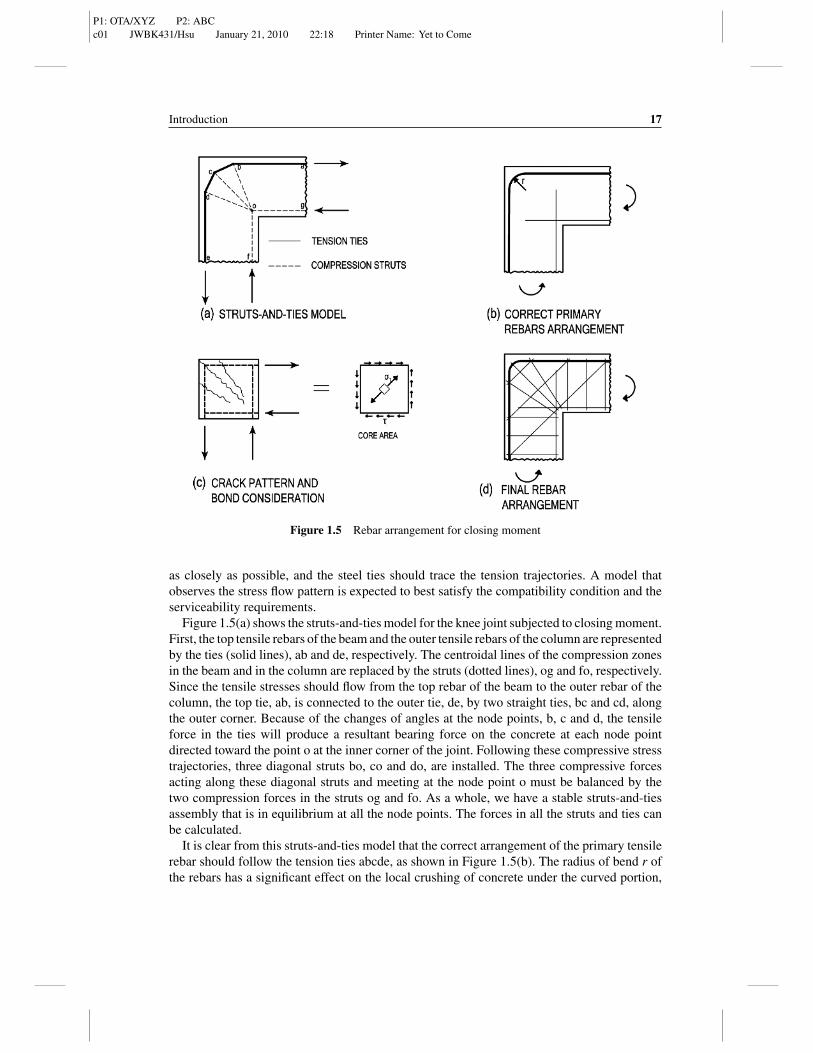
Figure 1.5 Rebar arrangement for closing moment
as closely as possible, and the steel ties should trace the tension trajectories. A model thatobserves the stress flow pattern is expected to best satisfy the compatibility condition and theserviceability requirements.
Figure 1.5(a) shows the struts-and-ties model for the knee joint subjected to closing moment.First, the top tensile rebars of the beam and the outer tensile rebars of the column are representedby the ties (solid lines), ab and de, respectively. The centroidal lines of the compression zonesin the beam and in the column are replaced by the struts (dotted lines), og and fo, respectively.Since the tensile stresses should flow from the top rebar of the beam to the outer rebar of thecolumn, the top tie, ab, is connected to the outer tie, de, by two straight ties, bc and cd, alongthe outer corner. Because of the changes of angles at the node points, b, c and d, the tensileforce in the ties will produce a resultant bearing force on the concrete at each node pointdirected toward the point o at the inner corner of the joint. Following these compressive stresstrajectories, three diagonal struts bo, co and do, are installed. The three compressive forcesacting along these diagonal struts and meeting at the node point o must be balanced by thetwo compression forces in the struts og and fo. As a whole, we have a stable struts-and-tiesassembly that is in equilibrium at all the node points. The forces in all the struts and ties canbe calculated.
It is clear from this struts-and-ties model that the correct arrangement of the primary tensilerebar should follow the tension ties abcde, as shown in Figure 1.5(b). The radius of bend r ofthe rebars has a significant effect on the local crushing of concrete under the curved portion,
P1: OTA/XYZ P2: ABCc01 JWBK431/Hsu January 21, 2010 22:18 Printer Name: Yet to Come
18 Unified Theory of Concrete Structures
as well as the compression failure of the diagonal struts near the point o. According to anextensive series of full-scale tests by Bai et al. (1991), the reinforcement index, ω = ρ fy/ f ′
c ,of the tension steel at the end section of the beam should be a function of the radius ratio r/d,and should be limited to:
ω = 2.2r
d(1.1)
and
ω = 0.33 + 0.2r
dfor
r
d≤ 0.6 (1.2)
where d is the effective depth at the end section of the beam. The compressive strength of thestandard cylinder f
′c has been taken as 77% of the compressive strength of the 20 cm cubes
used in the tests to define the reinforcement index ω. Equation (1.1) is governed by the localcrushing of concrete directly under the curved portion of the tension rebars, and Equation (1.2)by the compression failure of the diagonal struts near the point o.
In addition to the primary tension rebars, the two compression rebars should first followthe compression struts, og and fo, and then each be extended into the joint region for a lengthsufficient to satisfy the compression anchorage requirement, Figure 1.5(b).
A comparison of Figure 1.4(c) with Figure 1.5(b) reveals why the rebar arrangement inFigure 1.4(c) is deficient. Instead of connecting the top rebar of the beam and the outer rebarof the column by a single steel bar, these two rebars in Figure 1.4(c) are actually splicedtogether along the edge of the outer corner. This kind of splicing is notoriously weak becausethe splice is unconfined along the edge of the outer corner and its length is limited. If splicesare desired, they should be located away from the joint region and be placed in a well-confinedregion of the member, either inside the column or inside the beam.
In addition to the primary rebars, we must now consider the secondary rebar arrangement.Secondary rebars are provided for two purposes. First, they are designed to control cracks, andsecond, they are added to prevent premature failure. The crack pattern of a knee joint undera closing moment is shown in Figure 1.5(c). The direction of the cracks is determined by thestress state in the joint region. To understand this stress state, we notice that the four tensionand compression rebars introduce, through bonding, the shear stresses τ around the core area.The shear stress produces the principal tensile stress σ 1, which determines the direction ofthe diagonal cracks as indicated. To control these diagonal cracks, a set of opposing diagonalrebars perpendicular to the diagonal cracks are added, as shown in Figure 1.5(d).
Figure 1.5(d) also includes a set of inclined closed stirrups which radiate from the innercorner toward the outer corner. This set of closed stirrups is added to prevent two possible typesof premature failure. First, since the curved portion of a primary tension rebar in Figure 1.5(b)exerts a severe bearing pressure on the concrete, it could split the concrete directly beneath,along the plane of the frame. The outer horizontal branches of the inclined stirrups, whichare perpendicular to the plane of the frame, would serve to prevent such premature failures.Second, concrete in the vicinity of point o is subjected to extremely high compression stressesfrom all directions. The three remaining branches of the inclined closed stirrups would serveto confine the concrete in this area.
P1: OTA/XYZ P2: ABCc01 JWBK431/Hsu January 21, 2010 22:18 Printer Name: Yet to Come
Introduction 19
1.4.3.2 Knee Joint under Opening Moment
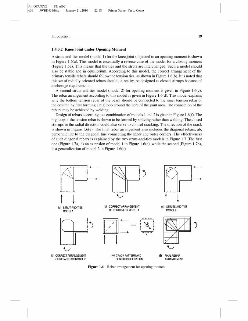
A struts-and-ties model (model 1) for the knee joint subjected to an opening moment is shownin Figure 1.6(a). This model is essentially a reverse case of the model for a closing moment(Figure 1.5a). This means that the ties and the struts are interchanged. Such a model shouldalso be stable and in equilibrium. According to this model, the correct arrangement of theprimary tensile rebars should follow the tension ties, as shown in Figure 1.6(b). It is noted thatthis set of radially oriented rebars should, in reality, be designed as closed stirrups because ofanchorage requirements.
A second struts-and-ties model (model 2) for opening moment is given in Figure 1.6(c).The rebar arrangement according to this model is given in Figure 1.6(d). This model explainswhy the bottom tension rebar of the beam should be connected to the inner tension rebar ofthe column by first forming a big loop around the core of the joint area. The connection of therebars may be achieved by welding.
Design of rebars according to a combination of models 1 and 2 is given in Figure 1.6(f). Thebig loop of the tension rebar is shown to be formed by splicing rather than welding. The closedstirrups in the radial direction could also serve to control cracking. The direction of the crackis shown in Figure 1.6(e). The final rebar arrangement also includes the diagonal rebars, ab,perpendicular to the diagonal line connecting the inner and outer corners. The effectivenessof such diagonal rebars is explained by the two struts-and-ties models in Figure 1.7. The firstone (Figure 1.7a), is an extension of model 1 in Figure 1.6(a), while the second (Figure 1.7b),is a generalization of model 2 in Figure 1.6(c).
Figure 1.6 Rebar arrangement for opening moment
P1: OTA/XYZ P2: ABCc01 JWBK431/Hsu January 21, 2010 22:18 Printer Name: Yet to Come
20 Unified Theory of Concrete Structures
Figure 1.7 Struts-and-ties models showing effectiveness of diagonal rebars
1.4.3.3 Knee Joint under both Closing and Opening Moments
The rebar arrangement in a knee joint subjected to both closing and opening moments, as inearthquake loadings, is shown in Figure 1.8. This arrangement is a combination of the twoschemes designed separately for a closing moment (Figure 1.5d) and for an opening moment(Figure 1.6f).
Knee joints can also be strengthened by adding a fillet, as shown in Figure 1.8(b). The rebararrangement could be simplified in such a joint, because the stresses at the joint region aresignificantly reduced.
1.4.4 Comments
Despite the clear concepts inherent in the struts-and-ties models, they are difficult to use in theactual design of the main regions of beams for three reasons.
Figure 1.8 Knee-joint rebar arrangement for both closing and opening moments (earthquake loading)
P1: OTA/XYZ P2: ABCc01 JWBK431/Hsu January 21, 2010 22:18 Printer Name: Yet to Come
Introduction 21
First, the design can be very tedious, since the forces in every strut and tie must be calculatedand scaled proportionally. Instead of treating a beam as a whole to simplify the design, thestruts-and-ties model is heading in the opposite direction by treating a beam as an assemblyof a large number of struts and ties.
Second, there are no definite objective criteria for the selection and the proportioning of thestruts and ties, even though recommendations have been made.
Third, and probably of most importance, there are indeed better and more sophisticatedmodels for the design of beams, which can take into account the compatibility conditionand the constitutive laws of materials. As mentioned in Section 1.2.2, Bernoulli’s linearcompatibility can be used for bending and axial loads in the main regions, and Mohr’s circularcompatibility can be used for shear and torsion. Detailed study of these better models is themain objective of this book.
Nevertheless, struts-and-ties models are well suited to guide the design of local regions,such as knee joints, for two reasons. First, the strain compatibility conditions in the localregions are usually too complicated to be employed. We have no choice but to rely on thestress equilibrium condition. Second, the local regions are of limited lengths compared withthe main regions (see Figure 1.1). Since the number of struts and ties in a local region islimited, the process of designing struts and ties is relatively easy.
P1: OTA/XYZ P2: ABCc01 JWBK431/Hsu January 21, 2010 22:18 Printer Name: Yet to Come