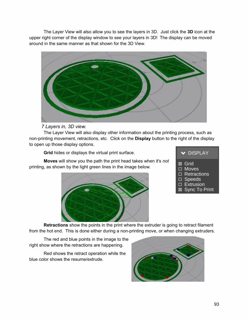
Orion Delta™ 3D Printer Manual Third Edition – Firmware 0.91 and Higher V3.05, September 28 th , 2016 MatterControl v1.2.2 Copyright 2015 By Gene Buckle – [email protected]Licensed as Creative Commons, Attribution-ShareAlike 3.0 This guide will take you through the steps to set up and operate your new 3D printer from SeeMeCNC. You’ll find instructions on calibration, software, maintenance and more all in this manual. As a new SeeMeCNC™ owner, you’ll also find a ton of great resources on the forums at forum . seemecnc . com 1
Transcript
Orion Delta™ 3D Printer ManualThird Edition – Firmware 0.91 and Higher
V3.05, September 28th, 2016MatterControl v1.2.2
Copyright 2015 By Gene Buckle – [email protected] as Creative Commons, Attribution-ShareAlike 3.0
This guide will take you through the steps to set up and operate your new 3D printer from SeeMeCNC. You’ll find instructions on calibration, software, maintenance and more all in this manual. As a new SeeMeCNC™ owner, you’ll also find a ton of great resources on the forums at forum . seemecnc . com
This document is your instruction manual for your new SeeMeCNC® 3D printer machine.Before using your new 3D printer, thoroughly read and understand this manual for safe and effective operation of the machine.
2
Warning
Adult supervision required. Children under 18 years of age require supervision.
Risk of Fire. Do not leave machine unattended.
Use genuine parts manufactured or designated by SeeMeCNC.
Keep a copy of this manual near the machine, easily accessible to all operators.
Use of this machine is at your own risk.
Personal property damage, serious injury or death can result from not following instructions or warning in the manual or misuse of the machine.Automatic machine can start unexpectedly. Pay close attention and keep clear while power is connected to the machine
The machine power supply is connected to AC voltage and can be hazardous. Disconnect power before servicing this machine.
The hot end of the machine can reach very high temperatures of 700F and can cause serious burns. The heated print surfaces (heated bed) can also reach temperatures high enough to cause severe burns. Allow both to cool for 20 minutes after turning off power.
Use caution near moving parts of the machine. Keep body and loose articles clear.
Poisonous gas, smoke, or fumes could be emitted by some materials you could use with the machine. In such case, you should install ventilation.
Choking Hazard. This machine contains small parts and can produce small parts which can be a choking hazard to children.
Visit http://www.seemecnc.com to contact us if you have any questions.
Table of Contents
Un-Boxing your new Orion Delta™ 3D Printer.............................................................................5Installing the LCD Control Panel, USB Cable and SD Card.........................................................9Installing the Power Cord and Spool Holder..............................................................................14Loading Filament.......................................................................................................................18Powering Up your new Orion Delta™ 3D Printer for the First Time............................................21The LCD Control Panel..............................................................................................................22Setting the Z height....................................................................................................................25Leveling your new Orion Delta™ 3D Printer (The Easy Way!)...................................................27A Simple Guide to Hot End Priming...........................................................................................32Printing from the SD Card..........................................................................................................34Changing Filament.....................................................................................................................37Printing From Your Computer.....................................................................................................40MatterControl Basics: Slicing.....................................................................................................48MatterControl Basics: Loading and Printing an Object...............................................................61Advanced MatterControl: Configuration.....................................................................................67Advanced MatterControl: Settings – Print..................................................................................71Advanced MatterControl: Settings – Filament............................................................................81Advanced MatterControl: Settings – Printer...............................................................................85Using the 3D View and Layer View............................................................................................88A Strategy for Successful (and Great!) Prints.............................................................................96
3
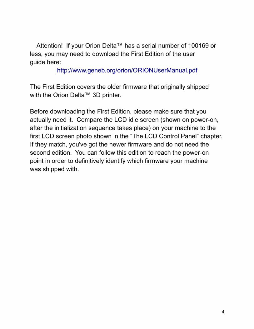
Attention! If your Orion Delta™ has a serial number of 100169 or less, you may need to download the First Edition of the user guide here:
http://www.geneb.org/orion/O RIONUserManual.pdf
The First Edition covers the older firmware that originally shipped with the Orion Delta™ 3D printer.
Before downloading the First Edition, please make sure that youactually need it. Compare the LCD idle screen (shown on power-on,after the initialization sequence takes place) on your machine to thefirst LCD screen photo shown in the “The LCD Control Panel” chapter.If they match, you've got the newer firmware and do not need the second edition. You can follow this edition to reach the power-onpoint in order to definitively identify which firmware your machinewas shipped with.
With your box standing in the upright position, carefully cut the packing tape along the top edges and across the taped seam in the box.
After you’ve cut the tape, open the top of the box being careful of any packaging staples.You’ll find the machine tucked inside and wrapped in a protective expanding foam shell. Remove the machine and foam all as one by pulling straight up out of the box. Be careful not todrop the machine once it’s out of the box and the foam is still around it.
5
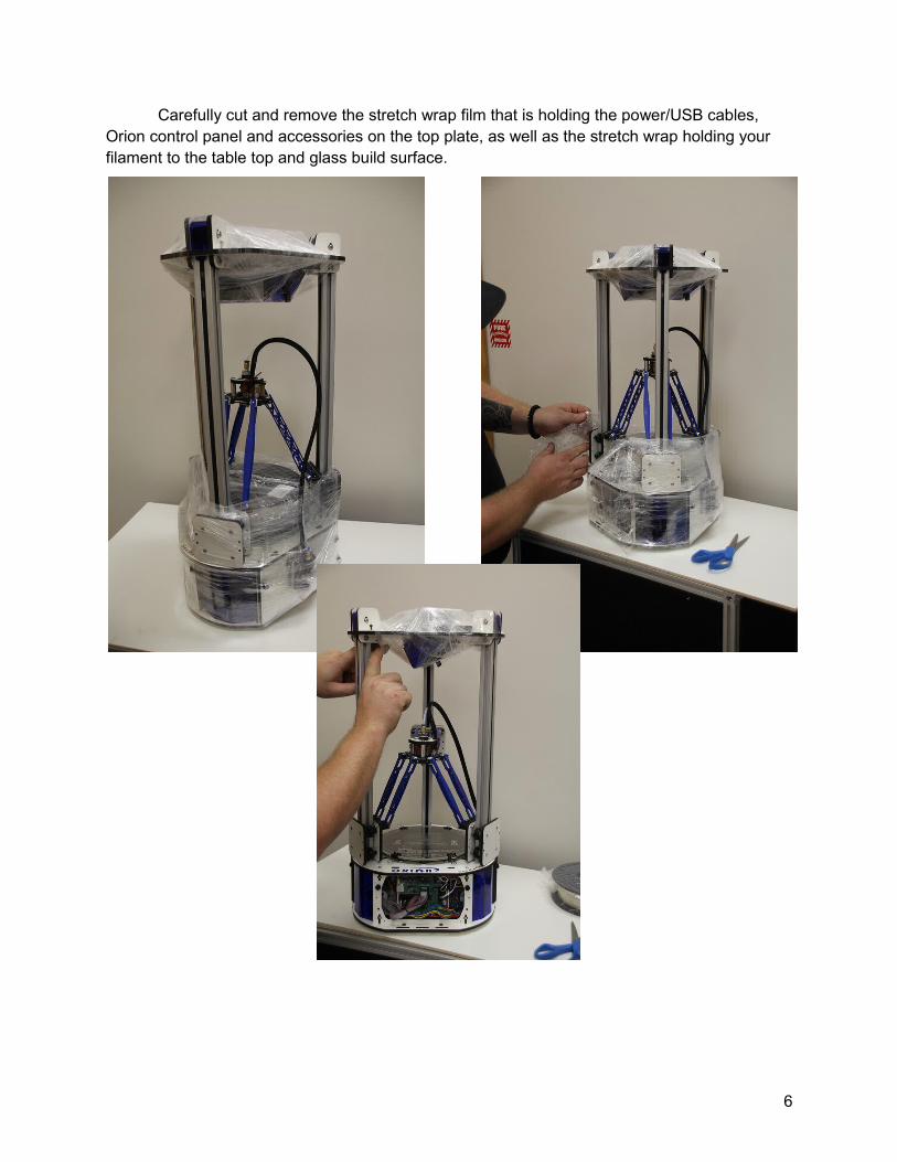
Carefully cut and remove the stretch wrap film that is holding the power/USB cables, Orion control panel and accessories on the top plate, as well as the stretch wrap holding your filament to the table top and glass build surface.
6
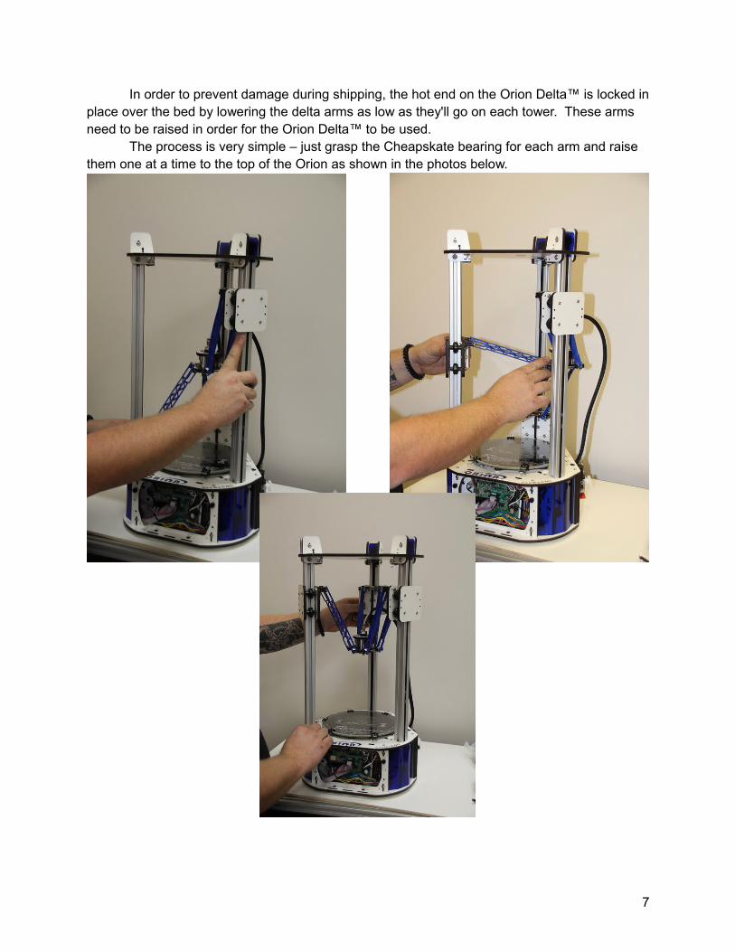
In order to prevent damage during shipping, the hot end on the Orion Delta™ is locked inplace over the bed by lowering the delta arms as low as they'll go on each tower. These arms need to be raised in order for the Orion Delta™ to be used.
The process is very simple – just grasp the Cheapskate bearing for each arm and raise them one at a time to the top of the Orion as shown in the photos below.
7
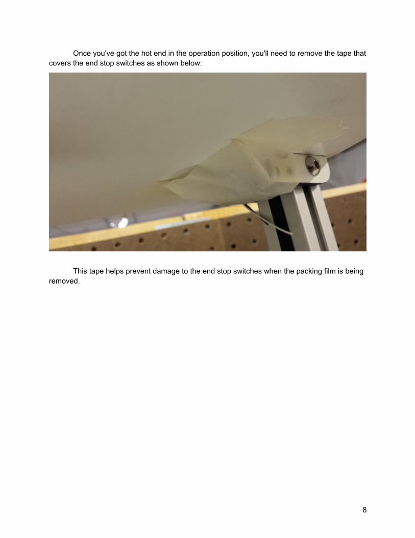
Once you've got the hot end in the operation position, you'll need to remove the tape thatcovers the end stop switches as shown below:
This tape helps prevent damage to the end stop switches when the packing film is being removed.
8
Installing the LCD Control Panel, USB Cable and SD Card
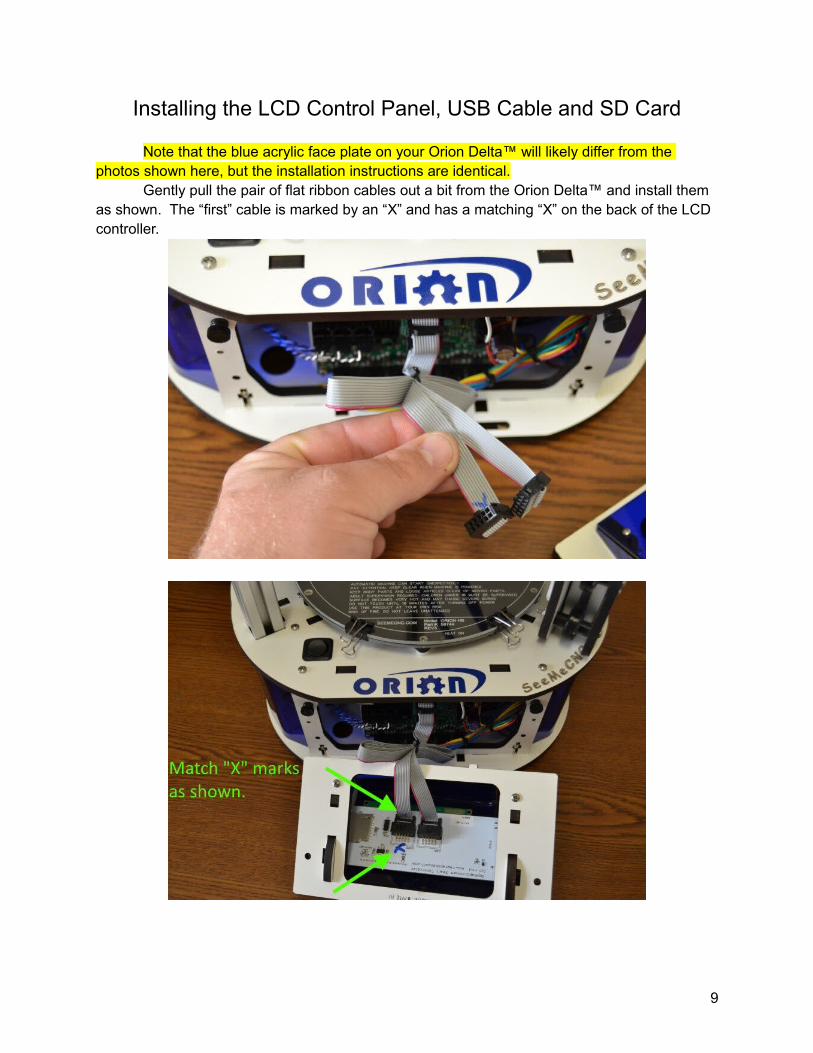
Note that the blue acrylic face plate on your Orion Delta™ will likely differ from the photos shown here, but the installation instructions are identical.
Gently pull the pair of flat ribbon cables out a bit from the Orion Delta™ and install them as shown. The “first” cable is marked by an “X” and has a matching “X” on the back of the LCD controller.
9
The USB cable only needs to be used if you wish to manually control the machine from the software on your PC. You can print and do most calibration standalone, without the USB cable attached. We recommend hooking it up now, so if you need to connect it to your computer to make changes etc., the cable is already installed.
Pass the end of the USB cable up through the hole in the bottom left of the base and plug it into the USB input on the electronics board.
10
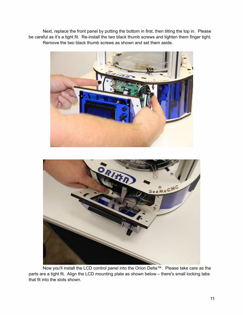
Next, replace the front panel by putting the bottom in first, then tilting the top in. Please be careful as it’s a tight fit. Re-install the two black thumb screws and tighten them finger tight.
Remove the two black thumb screws as shown and set them aside.
Now you'll install the LCD control panel into the Orion Delta™. Please take care as the parts are a tight fit. Align the LCD mounting plate as shown below – there's small locking tabs that fit into the slots shown.
11
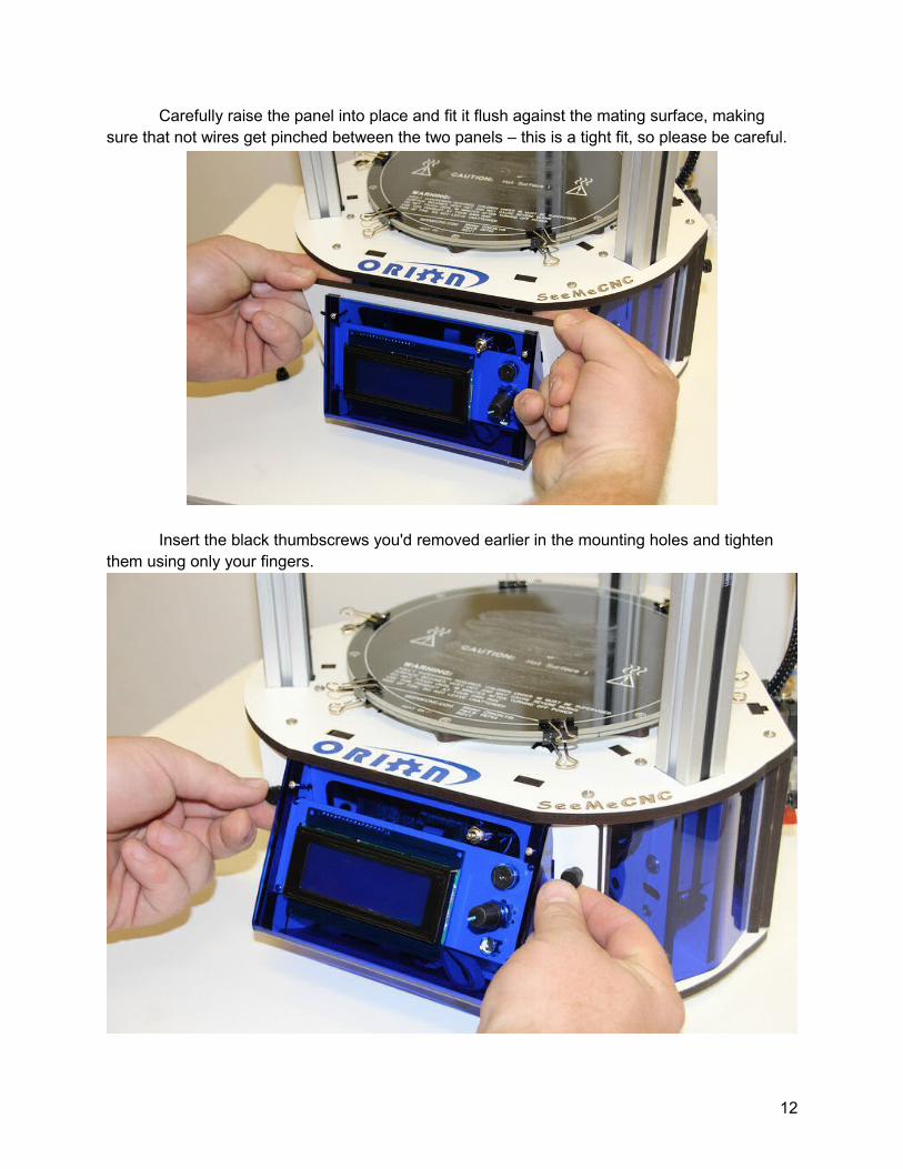
Carefully raise the panel into place and fit it flush against the mating surface, making sure that not wires get pinched between the two panels – this is a tight fit, so please be careful.
Insert the black thumbscrews you'd removed earlier in the mounting holes and tighten them using only your fingers.
12
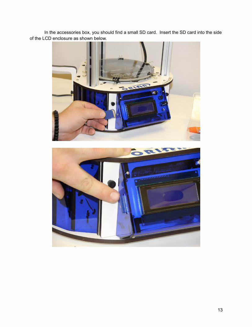
In the accessories box, you should find a small SD card. Insert the SD card into the sideof the LCD enclosure as shown below.
13
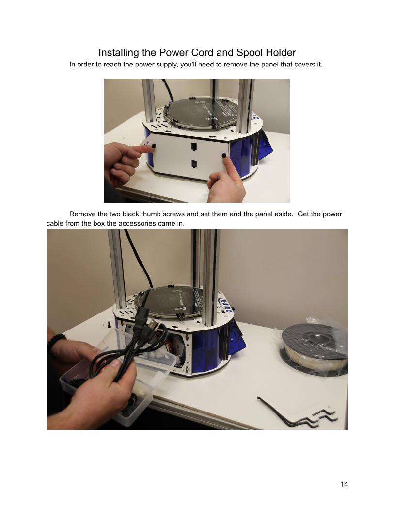
Installing the Power Cord and Spool HolderIn order to reach the power supply, you'll need to remove the panel that covers it.
Remove the two black thumb screws and set them and the panel aside. Get the power cable from the box the accessories came in.
14
If you're outside the USA and live in a country where the A/C electrical power is 240V, you'll need to flip the switch on the power supply to its 240V setting. This switch is located right below the power socket as shown. You can use a flat tip screwdriver to change its position.
The power cable is installed by routing it through the hole in the base of the Orion Delta™ and plugging it into the socket on the power supply. It's a tight fit, so take your time.
15
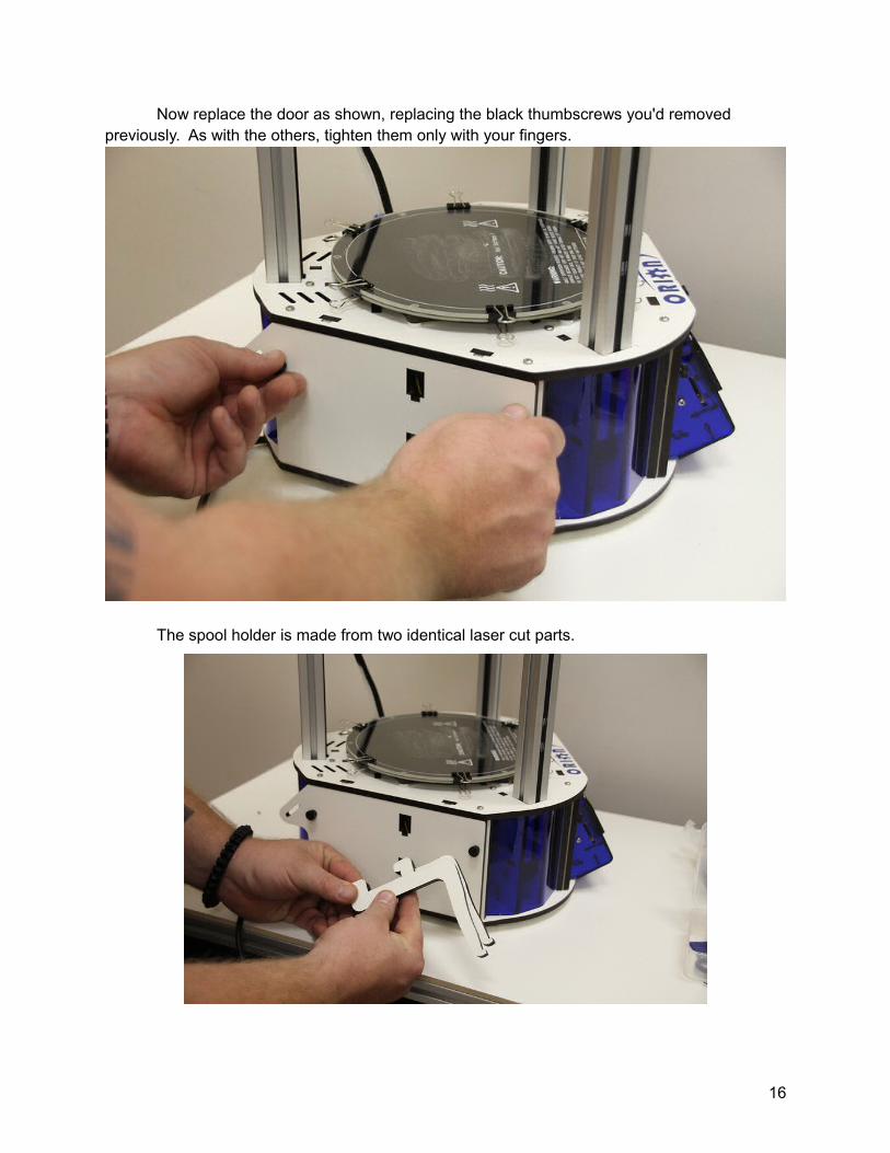
Now replace the door as shown, replacing the black thumbscrews you'd removed previously. As with the others, tighten them only with your fingers.
The spool holder is made from two identical laser cut parts.
16
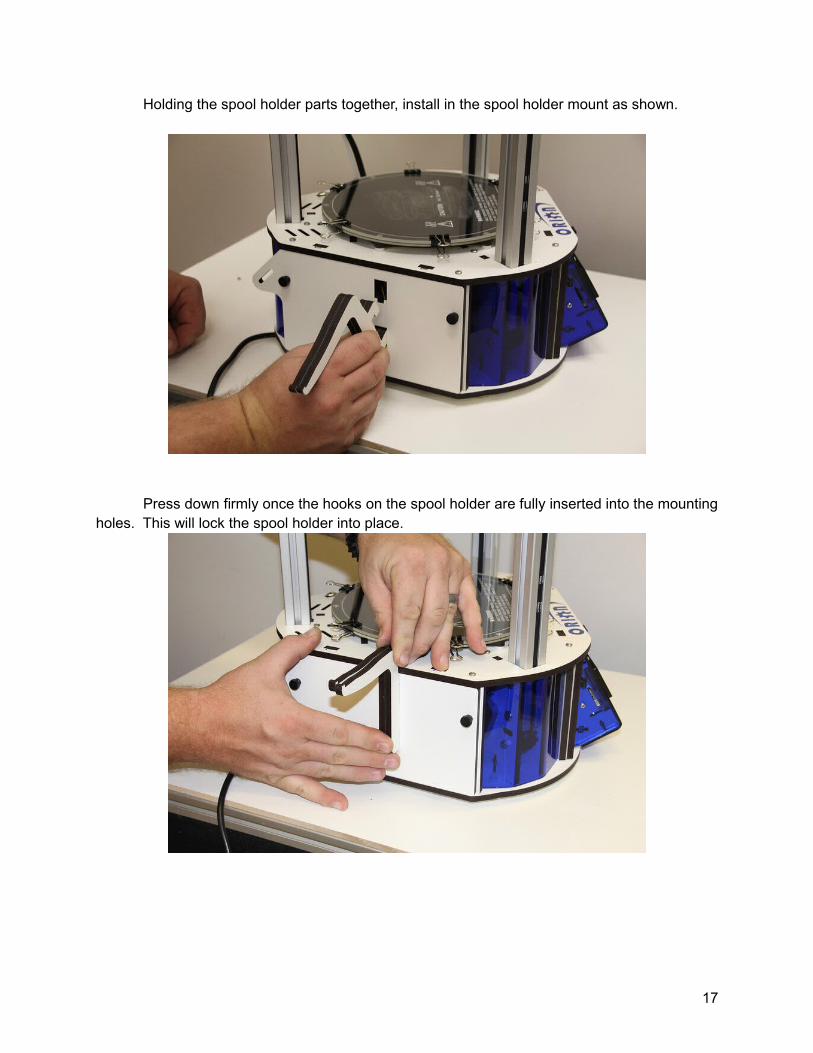
Holding the spool holder parts together, install in the spool holder mount as shown.
Press down firmly once the hooks on the spool holder are fully inserted into the mountingholes. This will lock the spool holder into place.
17
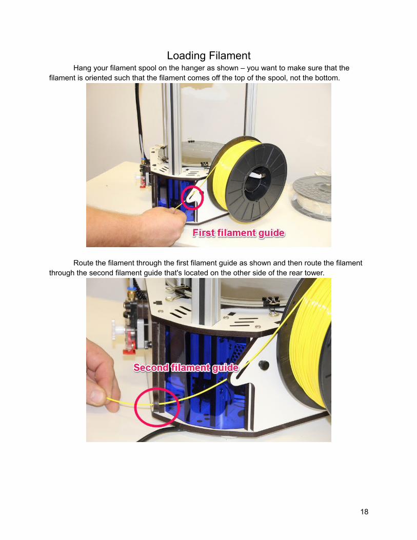
Loading FilamentHang your filament spool on the hanger as shown – you want to make sure that the
filament is oriented such that the filament comes off the top of the spool, not the bottom.
Route the filament through the first filament guide as shown and then route the filament through the second filament guide that's located on the other side of the rear tower.
18
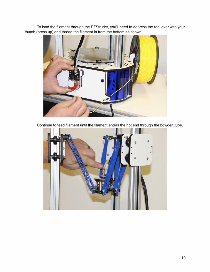
To load the filament through the EZStruder, you'll need to depress the red lever with yourthumb (press up) and thread the filament in from the bottom as shown.
Continue to feed filament until the filament enters the hot end through the bowden tube.
19
Finally, you'll want to remove the protective plastic sheet that covers the LCD.
20
Powering Up your new Orion Delta™ 3D Printer for the First Time
Plug the power cord into a grounded, three prong outlet. Orient the Orion Delta™ to face you and flip the power switch to the right.
You should be briefly greeted by a power on message similar to the one shown below.
After a short delay, the “front page” of the LCD should be displayed.
Now that you've got your Orion powered up, let's learn what it's all about!
21
The LCD Control PanelBefore we get into doing final configuration and printing with your new Orion Delta™ 3D
printer, let's take a moment to go over the LCD “home” screen so you'll understand what information is being presented to you.
1. Hot end Temperature. This is the temperature at the nozzle as measured by the thermistor in the hot end. It reads degrees Celsius – you'll quickly find that just about everything to do with 3D printing is done in Metric units of measure. FYI, 17.5C is 63.5F.
2. Bed Temperature. This is the temperature of the heated bed as measured by the thermistor in the center of the bed. Just like the nozzle, it reads in degrees Celsius.
3. Speed Rate. This is the speed multiplier field. Normally it will read 100%, but if you've changed the speed control from the host software, this number will
display what that setting is. We'll get into this in more detail later.
22
4. Target Hot End Temperature. When you're printing a part, this field will show you what temperature you've set the hot end to.
5. Target Bed Temperature. This shows what temperature you've set the heated bed to.
6. Extrusion Flow Multiplier. This shows the flow rate of the extruder.
The current hot end and bed temperatures may differ from what you see above – it's entirely dependent on the temperature of the room that your Orion Delta™ is currently in.
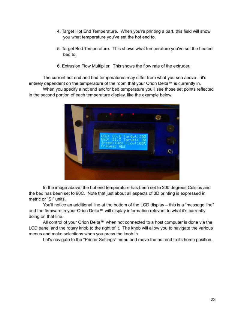
When you specify a hot end and/or bed temperature you'll see those set points reflected in the second portion of each temperature display, like the example below.
In the image above, the hot end temperature has been set to 200 degrees Celsius and the bed has been set to 90C. Note that just about all aspects of 3D printing is expressed in metric or “SI” units.
You'll notice an additional line at the bottom of the LCD display – this is a “message line” and the firmware in your Orion Delta™ will display information relevant to what it's currently doing on that line.
All control of your Orion Delta™ when not connected to a host computer is done via the LCD panel and the rotary knob to the right of it. The knob will allow you to navigate the various menus and make selections when you press the knob in.
Let's navigate to the “Printer Settings” menu and move the hot end to its home position.
23
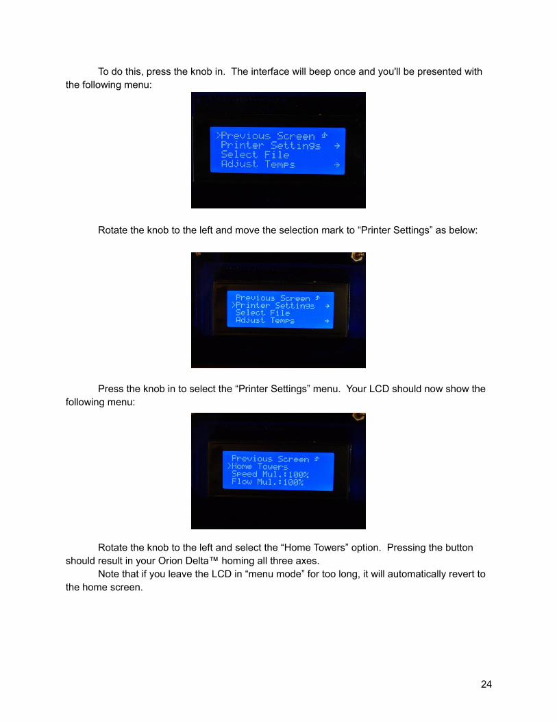
To do this, press the knob in. The interface will beep once and you'll be presented with the following menu:
Rotate the knob to the left and move the selection mark to “Printer Settings” as below:
Press the knob in to select the “Printer Settings” menu. Your LCD should now show the following menu:
Rotate the knob to the left and select the “Home Towers” option. Pressing the button should result in your Orion Delta™ homing all three axes.
Note that if you leave the LCD in “menu mode” for too long, it will automatically revert to the home screen.
24
Setting the Z height
Congratulations! Your new Orion Delta™ 3D printer is alive! But before we get to printing lets take a minute to set the Z height of the machine as it could have been bumped during shipping and it needs to be super accurate to get the best first-layer adhesion of your prints.
Using the control panel on the machine to set the Z height is really easy. You’ll find you may need to do this from time to time or after changing to a new build plate or nozzle etc. Prettymuch anything that could change the height as measured from the tip of the nozzle to the built plate.
To set the Z height you want to warm the bed and hot end to close to printing temperature to let any heat expansion take place. To do so, click on the knob and scroll to “Printer Settings” then “Preheat ABS” and press the knob. This will set the heated bed to 90c and the hot end to 200c. This is less than the melt temp for ABS, but a good holding temperature that will make sure that any ABS filament doesn’t burn as it sits in the hot end waiting for the bed to heat up. It may take up to 15 minutes to heat the bed to 90c depending on the room temperature, but it’s important to let it heat up before setting the Z height.
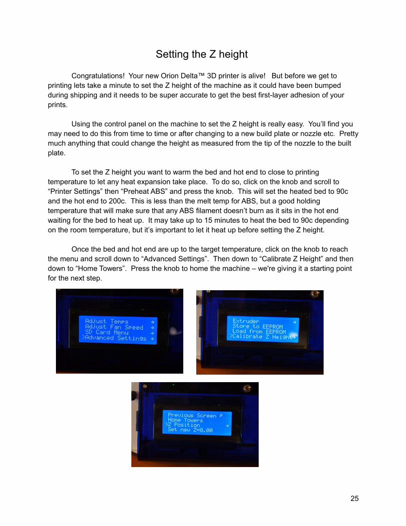
Once the bed and hot end are up to the target temperature, click on the knob to reach the menu and scroll down to “Advanced Settings”. Then down to “Calibrate Z Height” and then down to “Home Towers”. Press the knob to home the machine – we're giving it a starting point for the next step.
25
After the machine is homed, scroll to “Z Position” and click.
You'll see the display change to what is similar to the photo above. In order to move the platform down, you'll turn the knob counter-clockwise. If you turn it quickly, you'll get large movements and when you turn it very slowly, you'll get a .01mm per-click change.
Use the knob to lower the platform so that the nozzle tip is about 1/2” above the glass build surface.
Make sure the nozzle is clean and there is no filament hanging from the nozzle (Be careful, it’s hot now!). Take a single sheet of notebook paper and place it under the nozzle.
Turn the knob slowly and jog down until the nozzle just begins to “snag” on the paper. Now press the knob to return to the menu and scroll down to “Set new Z=0.00” to store the new Z height to memory. That’s it! You’ve now set the Z height to the table and you're now ready to prime the hot end and begin your first print!
26
Leveling your new Orion Delta™ 3D Printer (The Easy Way!)
Sometimes the abuse the Orion can experience during shipping can adversely effect the factory calibration. If that's the case with your printer, you can use this easy to follow guide in order to re-calibrate your Orion. This procedure was written by the gentleman that built and calibrated your printer, so there literally is no more authoritative source for the process.
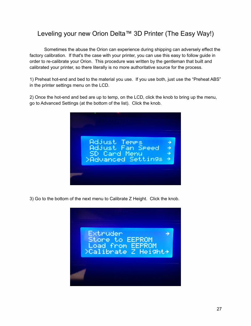
1) Preheat hot-end and bed to the material you use. If you use both, just use the “Preheat ABS”in the printer settings menu on the LCD.
2) Once the hot-end and bed are up to temp, on the LCD, click the knob to bring up the menu, go to Advanced Settings (at the bottom of the list). Click the knob.
3) Go to the bottom of the next menu to Calibrate Z Height. Click the knob.
27
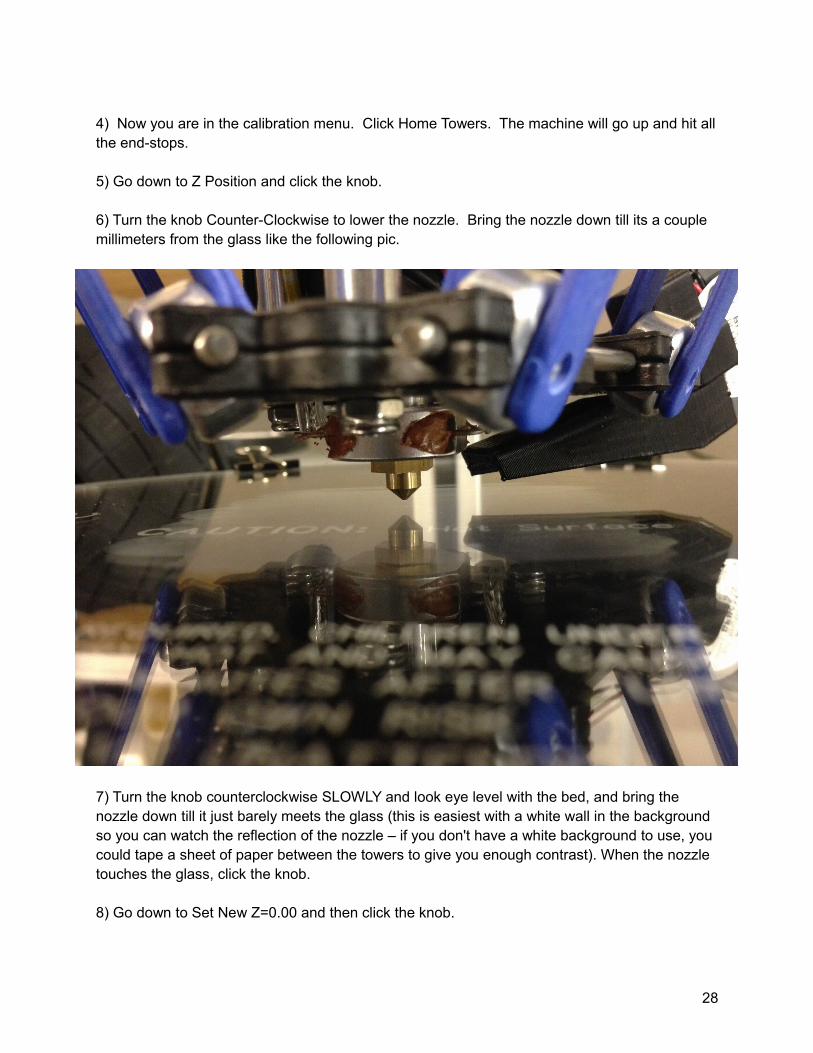
4) Now you are in the calibration menu. Click Home Towers. The machine will go up and hit allthe end-stops.
5) Go down to Z Position and click the knob.
6) Turn the knob Counter-Clockwise to lower the nozzle. Bring the nozzle down till its a couple millimeters from the glass like the following pic.
7) Turn the knob counterclockwise SLOWLY and look eye level with the bed, and bring the nozzle down till it just barely meets the glass (this is easiest with a white wall in the background so you can watch the reflection of the nozzle – if you don't have a white background to use, you could tape a sheet of paper between the towers to give you enough contrast). When the nozzle touches the glass, click the knob.
8) Go down to Set New Z=0.00 and then click the knob.
28
9) Go to Home Towers. Click the knob. You have now set the z height, and now it is time to calibrate the towers.
10) Using the selector knob on the Orion, scroll to the Select File menu option and choose the CALIBRATIONS sub-directory:
Then chose the TOWERS.GCO file:
This will run the tower calibration routine. Watch closely as the machine will home, then the nozzle will drop to 0.2mm ABOVE the glass. The gap will look like the following image.
After it drops to the center position, it will travel to the X tower. DO NOT pay attention to what the nozzle does while traveling, what you must pay attention to is when it pauses.
29
The nozzle will pause at the X corner, then return to the center, and move to the Y tower and pause. After the pause, it will again move to the center, and move to the Z tower, pause, and return to the center.
Your focus should be is on the nozzle when it pauses. You want to compare the gap at the tower to the gap at the center.
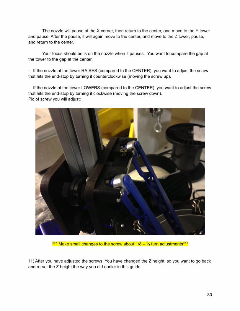
– If the nozzle at the tower RAISES (compared to the CENTER), you want to adjust the screw that hits the end-stop by turning it counterclockwise (moving the screw up).
– If the nozzle at the tower LOWERS (compared to the CENTER), you want to adjust the screwthat hits the end-stop by turning it clockwise (moving the screw down).Pic of screw you will adjust:
*** Make small changes to the screw about 1/8 – ¼ turn adjustments***
11) After you have adjusted the screws, You have changed the Z height, so you want to go backand re-set the Z height the way you did earlier in this guide.
30
12) Re-run the TOWERS.GCO file and watch as you did before, again noting the changes in the nozzle at each pause. You will run through these steps till the nozzle remains the same height at each tower when compared to the center.
If the nozzle goes the same direction on all 3 towers (such as you have the gap in the center, and at every tower the nozzle lowers. Or you have the gap at the center and at all 3 pauses the nozzle raises), you will adjust the radius in the following way.
13a) If from the center gap, the nozzle goes DOWN toward the glass at ALL 3 TOWERS, load your host software and bring up the EEPROM information. You will look for Horizontal Radius. You want to RAISE that number. I suggest raising it by 0.2 and run towers.gcode to see the change, and keep raising the number till the gap evens out (changing this number will not make you need to re-set your z height, it will just raise the outer edges where the nozzle pauses).
13b) If from the center gap, the nozzle goes UP away from the glass at ALL 3 TOWERS, load your host software and bring up the EEPROM information. You will look for Horizontal Radius. You want to LOWER that number. I suggest raising it by 0.2 and run towers.gcode to see the change, and keep raising the number till the gap evens out (changing this number will not make you need to re-set your z height, it will just lower the outer edges where the nozzle pauses).
After doing this, you will see any changes where one tower may be higher than another, if this isthe case, go back to adjusting the end-stop screws as before.
Typically it can take anywhere from 5-10 or so re-runs of the tweaks to get the gap to remain thesame at all 3 pauses compared to the center of the machine. Once the gap is the same at each tower compared to the center, your machine is calibrated and ready to print!
The guys at SeeMeCNC produced a really nice video that illustrates the entire calibrationprocess. You can view it using the link below.
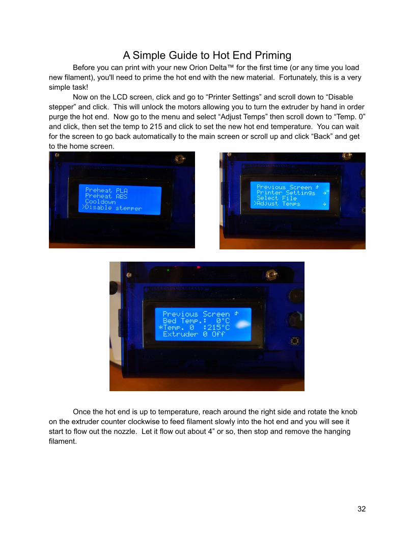
A Simple Guide to Hot End PrimingBefore you can print with your new Orion Delta™ for the first time (or any time you load
new filament), you'll need to prime the hot end with the new material. Fortunately, this is a very simple task!
Now on the LCD screen, click and go to “Printer Settings” and scroll down to “Disable stepper” and click. This will unlock the motors allowing you to turn the extruder by hand in orderpurge the hot end. Now go to the menu and select “Adjust Temps” then scroll down to “Temp. 0”and click, then set the temp to 215 and click to set the new hot end temperature. You can wait for the screen to go back automatically to the main screen or scroll up and click “Back” and get to the home screen.
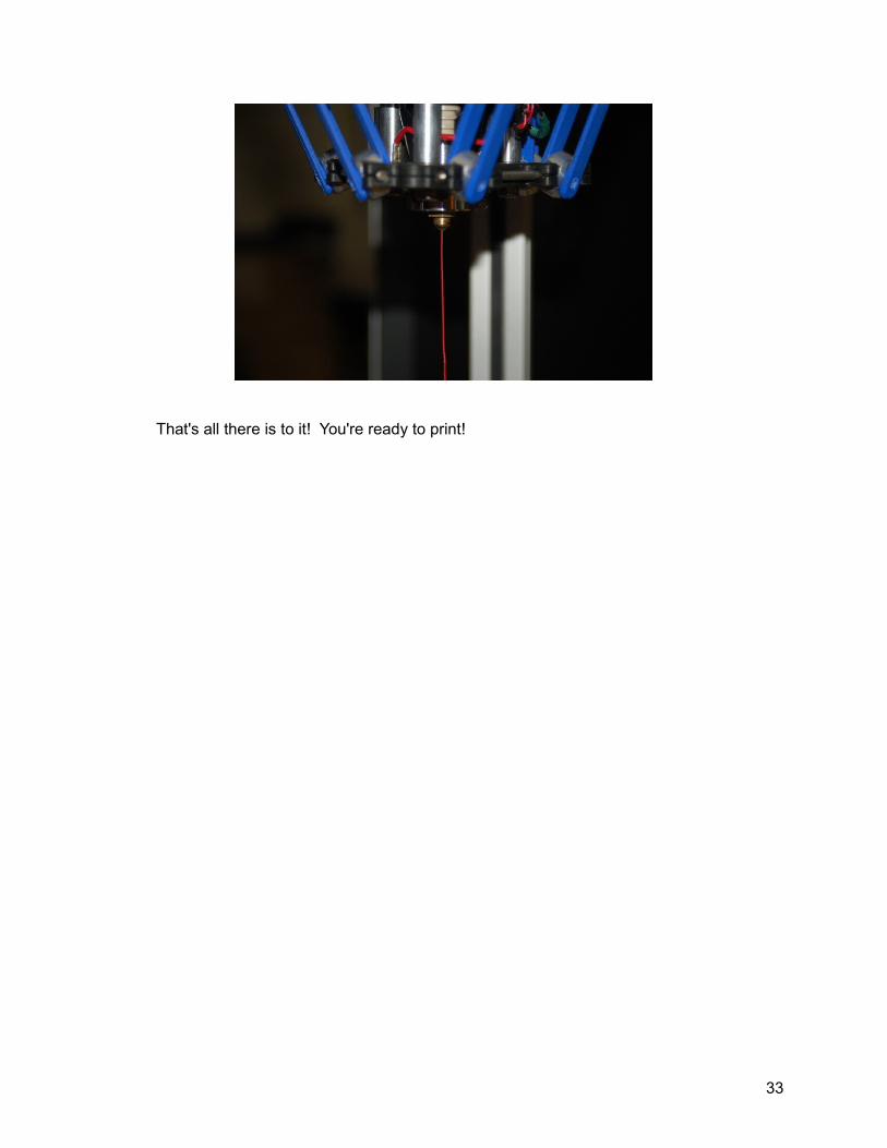
Once the hot end is up to temperature, reach around the right side and rotate the knob on the extruder counter clockwise to feed filament slowly into the hot end and you will see it start to flow out the nozzle. Let it flow out about 4” or so, then stop and remove the hanging filament.
32
That's all there is to it! You're ready to print!
33
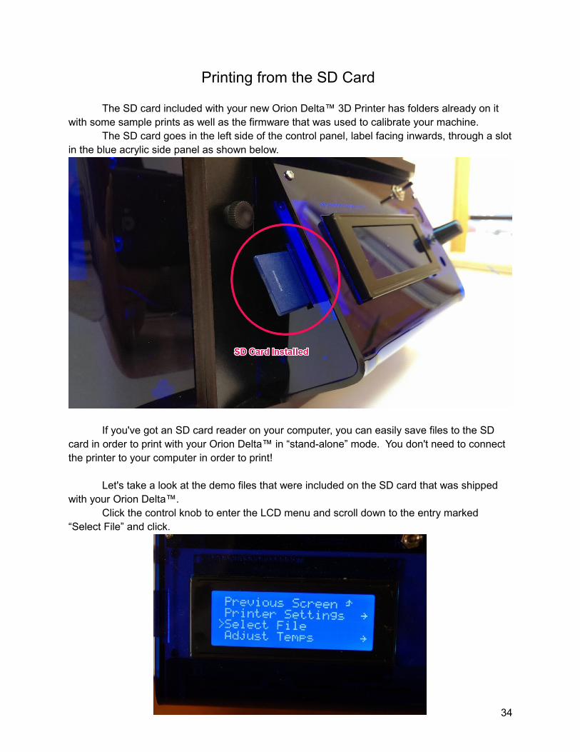
Printing from the SD Card
The SD card included with your new Orion Delta™ 3D Printer has folders already on it with some sample prints as well as the firmware that was used to calibrate your machine.
The SD card goes in the left side of the control panel, label facing inwards, through a slotin the blue acrylic side panel as shown below.
If you've got an SD card reader on your computer, you can easily save files to the SD card in order to print with your Orion Delta™ in “stand-alone” mode. You don't need to connect the printer to your computer in order to print!
Let's take a look at the demo files that were included on the SD card that was shipped with your Orion Delta™.
Click the control knob to enter the LCD menu and scroll down to the entry marked “Select File” and click.
34
Scroll to the “Print file” menu item and click. This will get you into the top level directory of the SD card.
The odd little symbol you see to the left of the directory names are actually little folder icons. This simply helps separate the directories from g-code and other files on the SD card.
Click the “GCODE” directory to see a list of the files included.
For this first print, go ahead and click on the file, “BLINKY.GCO”.
When you select the file name, the LCD controller will make a “chirping” sound and the heated bed will begin to heat up. Once the bed has reached its target temperature, the printer will home all three axes and then the hot end will begin its heating process. Once that has completed, the printer should begin the print.
35
Note – before you run a print job on your Orion Delta™, you need to apply a thin layer of adhesive using the included glue stick. This will allow the ABS plastic to stick tothe glass. Apply the glue stick in a thin layer of parallel lines. Let it dry and repeat the process, using lines perpendicular to the first layer. Once it dries you can print.
Do NOT apply the glue stick to a hot bed!
If you need to cancel a print job for any reason, simply turn the machine off and use the control panel to re-home the towers.
36
Changing Filament
Changing the filament on your Orion is a very simple process.First, you'll want to bring the hot end up to the temperature you normally set it at when
you're printing. Once the hot end is at operating temperature, pop the bowden tube off the hot end as
shown in the following steps.
1. Grip the bowden tube with one hand and press down the blue ring and pull up on the bowden tube. You may need to depress the red release lever on the extruder in order to get enough slack to pull the bowden tube free of the hotend fitting.
37
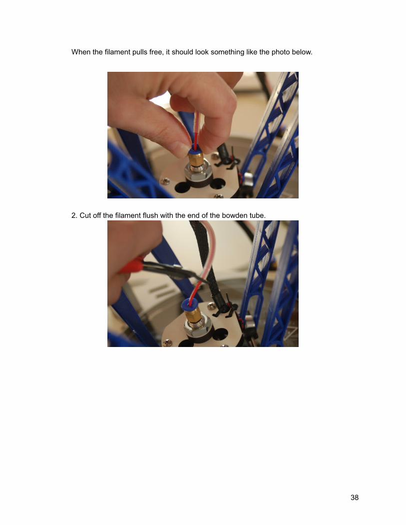
When the filament pulls free, it should look something like the photo below.
2. Cut off the filament flush with the end of the bowden tube.
38
3. Pull the filament stub from the hotend and then re-insert the bowden tube into the hotend, making sure it seats fully.
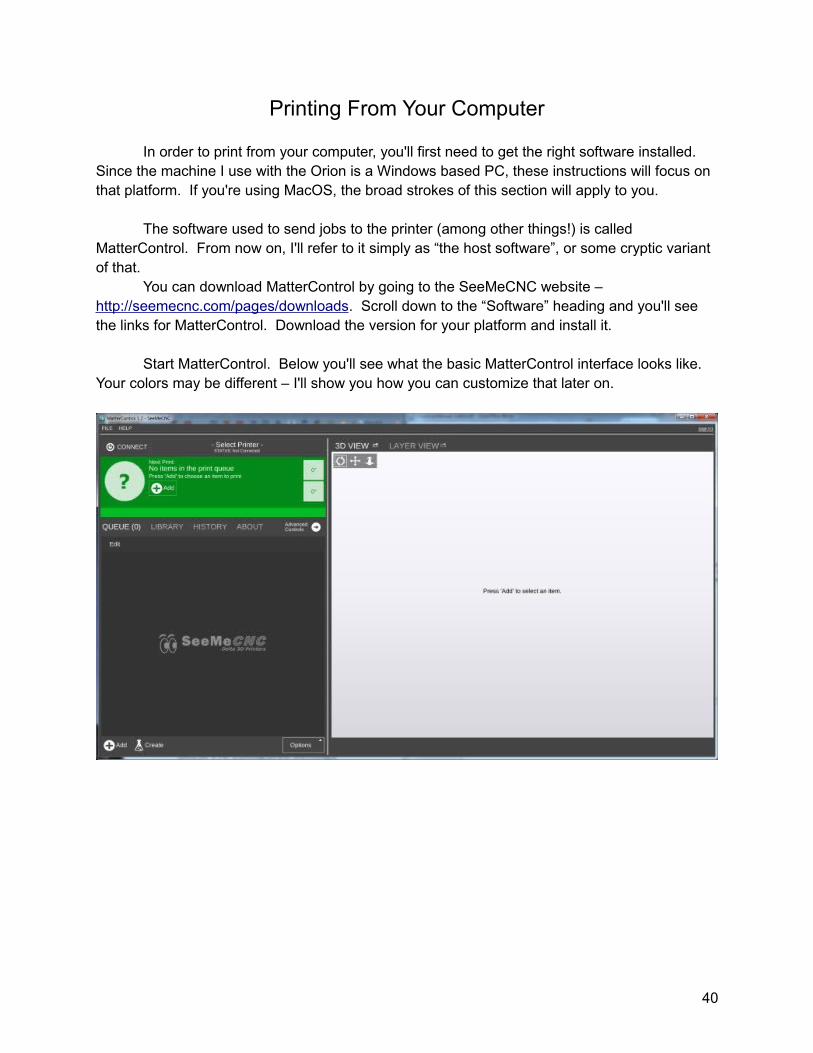
In order to print from your computer, you'll first need to get the right software installed. Since the machine I use with the Orion is a Windows based PC, these instructions will focus on that platform. If you're using MacOS, the broad strokes of this section will apply to you.
The software used to send jobs to the printer (among other things!) is called MatterControl. From now on, I'll refer to it simply as “the host software”, or some cryptic variant of that.
You can download MatterControl by going to the SeeMeCNC website – http://seemecnc.com/pages/downloads. Scroll down to the “Software” heading and you'll see the links for MatterControl. Download the version for your platform and install it.
Start MatterControl. Below you'll see what the basic MatterControl interface looks like. Your colors may be different – I'll show you how you can customize that later on.
Now that you've got MatterControl open, you need to tell it about the Orion so you can start printing! Click on “File” and then “Add Printer”. The following dialog will open:
This is where you can manage all your different printer configurations. Click the “Add” icon as indicated by the blue arrow.
Clicking on the Add icon willopen up the 3D Printer Setup dialog.Here is where you'll name the newprinter configuration and where youselect your printer model.
So go ahead and enter a printername and then chose “Orion” from the Select Model list. Once you've donethis, the Save & Continue button willappear at the bottom left corner of thewindow. Click on it to save your newprinter configuration.
41
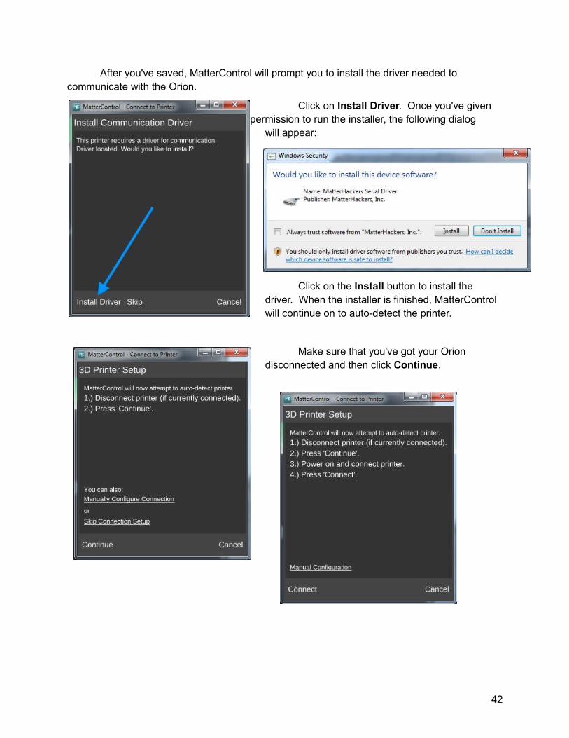
After you've saved, MatterControl will prompt you to install the driver needed to communicate with the Orion.
Click on Install Driver. Once you've given permission to run the installer, the following dialog
will appear:
Click on the Install button to install the driver. When the installer is finished, MatterControl will continue on to auto-detect the printer.
Make sure that you've got your Orion disconnected and then click Continue.
42
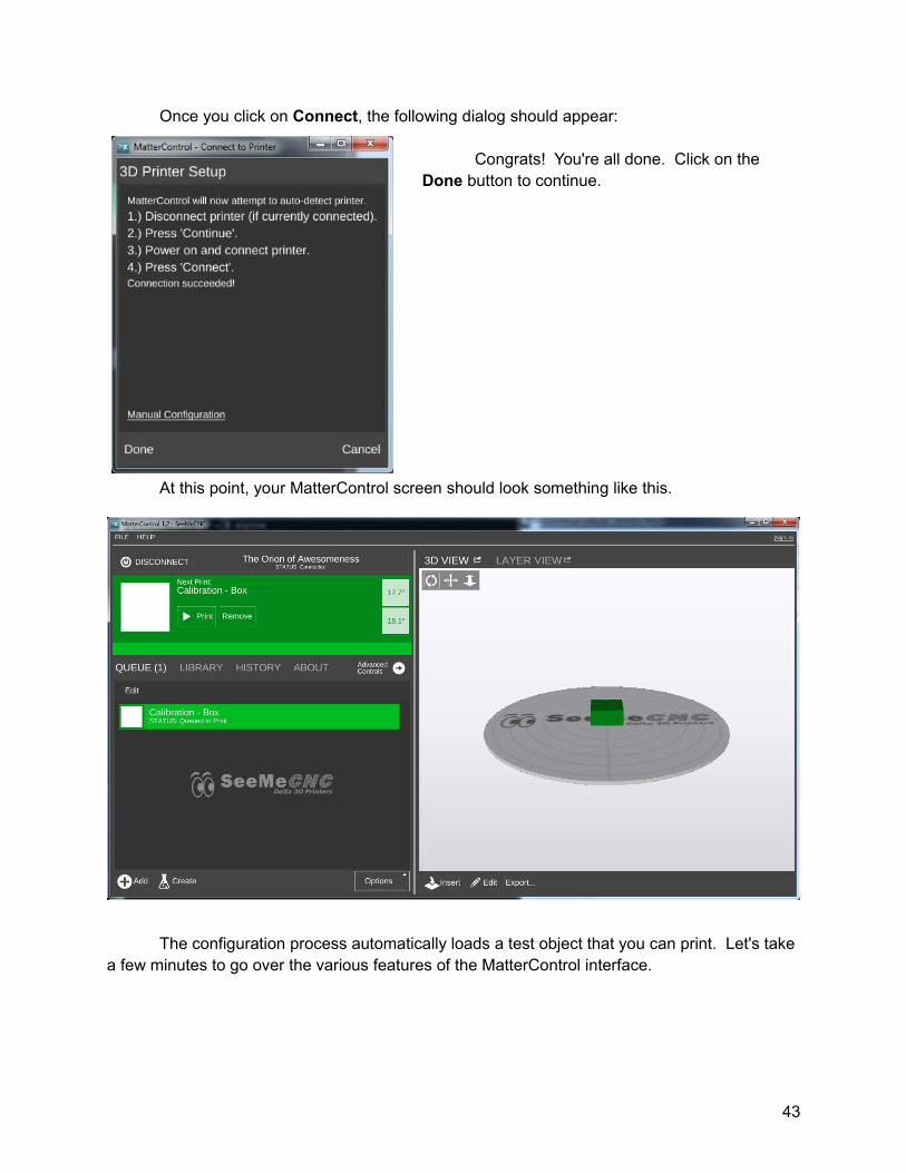
Once you click on Connect, the following dialog should appear:
Congrats! You're all done. Click on the Done button to continue.
At this point, your MatterControl screen should look something like this.
The configuration process automatically loads a test object that you can print. Let's take a few minutes to go over the various features of the MatterControl interface.
43
The MatterControl interface is split into two halves. The left half is where you can load objects or G-Code to print, start prints, and manually control the printer.
1. This is the print queue display. Ifnothing is queued up, you'll see amessage indicating that there noitems in the queue to print.
2. This is the temperature display.The top figure displays the currentnozzle temperature and the bottomfigure displays the current heatedbed temperature. Both values areshown in degrees Celsius.
3. Queue Count. This shows thenumber of objects currently in theprint queue.
4. This is your object library. We'll goover this in detail later.
5. Print History. This will show youwhat you've printed in the past alongwith statistics about each print.
6. About. This gives you informationabout the fine folks that createdMatterControl. It also includes abutton to send them feedback aswell as a button to check to see if any updates are available.
7. Advanced Controls – this is where you can manually control the printer. We'll cover this later as well.
8. The Add button will allow you to add objects or G-Code files to the print queue.
9. The Create button displays a list of available plug-ins that are used to create printable objectsright inside of MatterControl. We'll cover this one later.
10. The Options button opens a menu list that will allow you to export the current file and perform other operations on the print queue. You guessed it! We'll cover this one later.
44
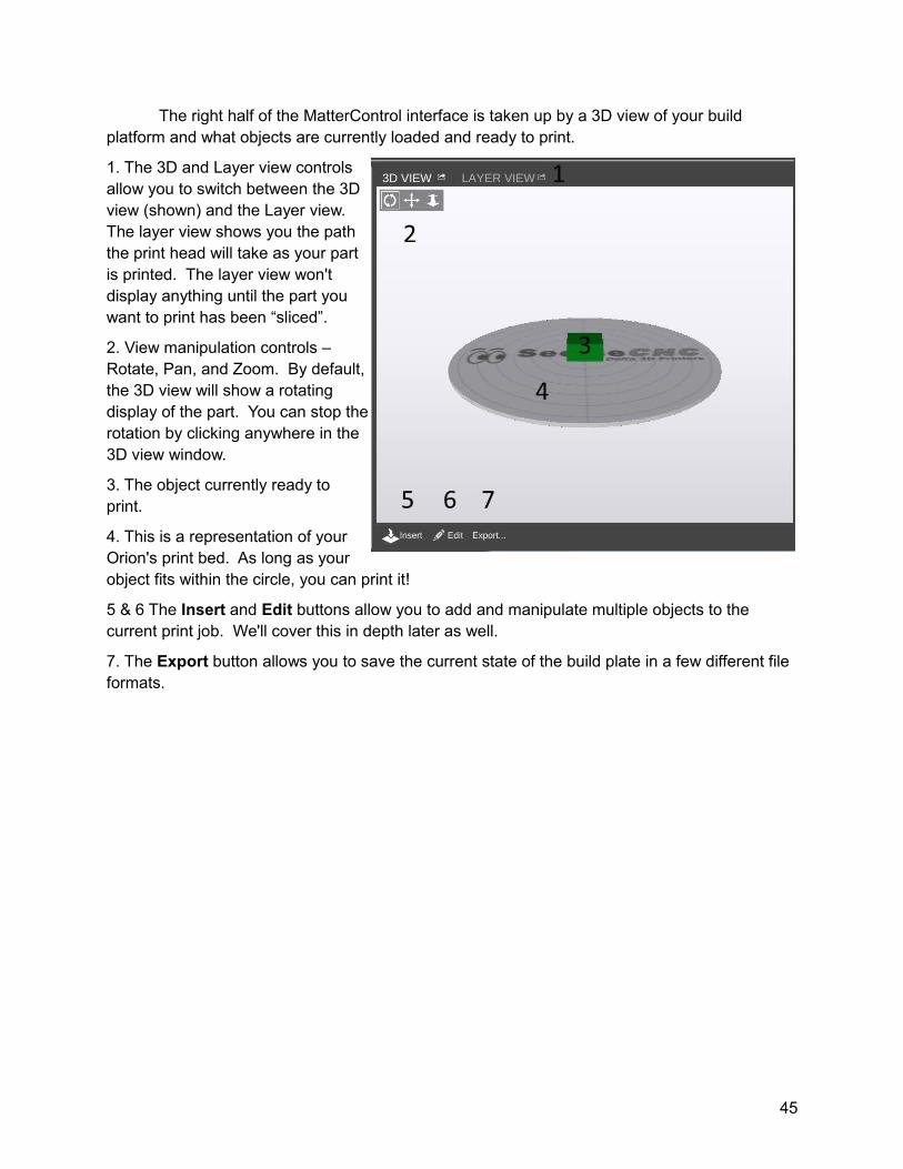
The right half of the MatterControl interface is taken up by a 3D view of your build platform and what objects are currently loaded and ready to print.
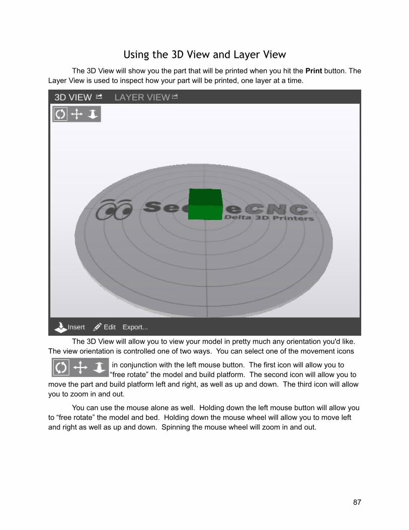
1. The 3D and Layer view controlsallow you to switch between the 3Dview (shown) and the Layer view.The layer view shows you the paththe print head will take as your partis printed. The layer view won'tdisplay anything until the part youwant to print has been “sliced”.
2. View manipulation controls –Rotate, Pan, and Zoom. By default,the 3D view will show a rotatingdisplay of the part. You can stop therotation by clicking anywhere in the3D view window.
3. The object currently ready toprint.
4. This is a representation of yourOrion's print bed. As long as yourobject fits within the circle, you can print it!
5 & 6 The Insert and Edit buttons allow you to add and manipulate multiple objects to the current print job. We'll cover this in depth later as well.
7. The Export button allows you to save the current state of the build plate in a few different file formats.
45
Since MatterControl was nice enough to provide us with a test object, what say we print it? Click on the Advanced Controls button on the left pane.
For right now we're only going to worry about the QUALITY and MATERIAL settings. Click on the QUALITY drop down and select Standard. Click on the MATERIAL drop down and choose the filament that you've got loaded in your Orion. Since I've got ABS loaded, that's what I chose. Make sure you've applied glue stick to the bed as mentioned earlier in this guide! Now click Print button at the top of the display to start the print job!
You'll notice right off that the display changes to show you what's going on. The status window will tell you what MatterControl thinks the print time will be as well as a progress bar along the bottom that gives you the actual percentage completed. (0.7% in the example below.)
Your Orion LCD will show you that the hot end and heated bed are coming up to temperature.
If you're printing with PLA,then your temperatures will bedifferent.
Kick back and relax! Oncethe Orion has it the temperaturetargets shown, the print will start!
I should note that the print time estimation is very, VERY optimistic. :)
46
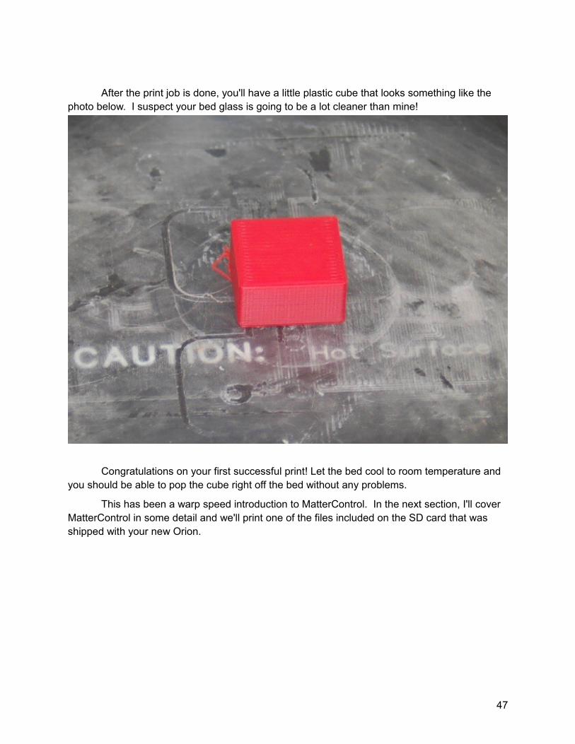
After the print job is done, you'll have a little plastic cube that looks something like the photo below. I suspect your bed glass is going to be a lot cleaner than mine!
Congratulations on your first successful print! Let the bed cool to room temperature and you should be able to pop the cube right off the bed without any problems.
This has been a warp speed introduction to MatterControl. In the next section, I'll cover MatterControl in some detail and we'll print one of the files included on the SD card that was shipped with your new Orion.
47
MatterControl Basics: SlicingMatterControl is a very complete 3D printing package and it's got a LOT of options.
Some people can find this intimidating, but I assure you – there's nothing to be worried about!
MatterControl is an integrated host application. This means that it provides everything needed to control the Orion and to prepare models for printing. The task of preparing a model for printing is called “slicing”. It's a very descriptive term for what is actually happening. In orderto print a 3D model, it needs to be converted from a solid object into a series of very thin layers that are in turn converted into G-Code (more on this later). For example, if your print layer height is 0.2mm, the slicing tool is going to “slice” your model into a number of layers – basicallythe model height divided by 0.2mm. For a tall part, this can mean a LOT of layers!
MatterControl provides three slicers for your use. MatterSlice, CuraEngine, and Slic3r. This guide will only cover the specifics of MatterSlice, but don't let that stop you from experimenting with and using the other slicers! I'll show you how to change the slicing engine later on in this guide.
The final task of the slicer is to translate the sliced layers of model into something called G-code. G-code is a simple control language that's used to position the print head and tell the extruder how much plastic to deliver and at what rate. Going into the details of G-code is beyond the scope of this guide, but if you'd like to learn more you can check out the following resources: http://en.wikipidia.org/wiki/G-code and http://reprap.org/wiki/G-code.
For the most part, you'll never directly interact with G-code, but it's nice to know what's going on behind the curtain!
I want you to click on the Advanced Controls button to bring up the Settings, Controls,and Configuration pane.
Click on the SETTINGS link to make sure your display follows (by and large) what you see below.
The first thing I want you to do is click on the Show Help check box that's highlighted by the arrow in the image above. This will turn on verbose descriptions of each one of the parameters available in the Settings page.
I'm going to only cover the “Simple” configuration settings for right now. There's a LOT that goes on to configuring your slicer and the Simple configuration setting allows many of thoseto be hidden until you're more comfortable with how your printer works.
Layer Height – This parameter tells the slicing engine how thin to make the layers whenit slices up the model as I described earlier. A good default layer height is 0.2 or 0.25mm. The lowest practical layer height with a 0.5mm nozzle is 0.1mm. You can go lower than that, but it requires a smaller nozzle diameter. You can also got a lot thicker, but that requires a larger nozzle. If you change the Quality from Standard to Coarse or Fine, you'll notice how the layer height changes.
49
Here's what the Coarse, Standard, and Fine layer heights look like when printing the little test cube in ABS plastic.
Starting from left to right, the layer heights are 0.1mm, 0.2mm and 0.3mm. You'll notice that the top layer on the 0.1mm print is kind of ratty and torn up. This is because the number of top layers is set to 3. This is perfectly ok with thicker layer heights, but it should have been set to at least 5 for the 0.1mm layer height that the Fine setting uses. You'll learn how to tweak thatin a little bit.
You can see how the smoothness of the sides decrease as the layer thickness increases. If you want to print something really quick, you could go up to a 0.35mm layer height. I wouldn't recommend anything over 0.40mm if you're using a 0.5mm nozzle however.
Fill Density – This parameter controls how solid your printed part is. The number is a percentage, from 0 (totally hollow) to 1 (totally solid). The default fill density (also known as “infill”) is 0.2 or 20%. The image below shows what that looks like inside our little test cube.
You can tweak the infill to get a morerobust or a lighter part. For most prints, 20% is agood infill value.
Later on I'll show you how to change to adifferent infill pattern. The one shown on theright is the Triangle pattern.
Support Material – Support material isused when the part you're printing has free-standing features (like the chin on a bust) oranother feature that requires it to be physically supported during the printing process. When
50
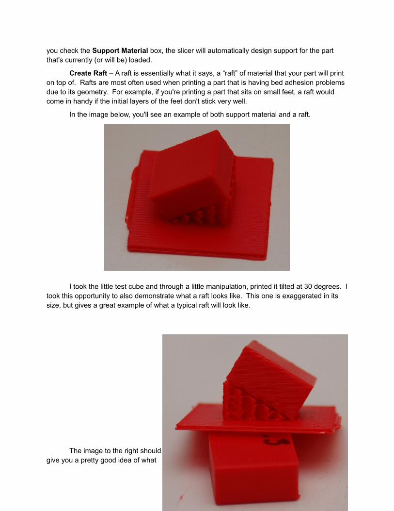
you check the Support Material box, the slicer will automatically design support for the part that's currently (or will be) loaded.
Create Raft – A raft is essentially what it says, a “raft” of material that your part will print on top of. Rafts are most often used when printing a part that is having bed adhesion problems due to its geometry. For example, if you're printing a part that sits on small feet, a raft would come in handy if the initial layers of the feet don't stick very well.
In the image below, you'll see an example of both support material and a raft.
I took the little test cube and through a little manipulation, printed it tilted at 30 degrees. Itook this opportunity to also demonstrate what a raft looks like. This one is exaggerated in its size, but gives a great example of what a typical raft will look like.
The image to the right shouldgive you a pretty good idea of what
51
the part looks like from the side. You can easily see the support material as well as the layer lines that will be at a 30 degree angle when the little cube is laid flat.
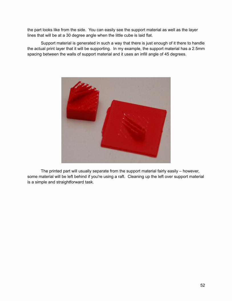
Support material is generated in such a way that there is just enough of it there to handlethe actual print layer that it will be supporting. In my example, the support material has a 2.5mmspacing between the walls of support material and it uses an infill angle of 45 degrees.
The printed part will usually separate from the support material fairly easily – however, some material will be left behind if you're using a raft. Cleaning up the left over support materialis a simple and straightforward task.
52
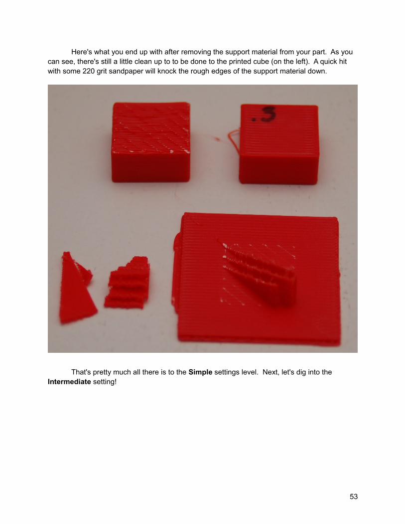
Here's what you end up with after removing the support material from your part. As you can see, there's still a little clean up to to be done to the printed cube (on the left). A quick hit with some 220 grit sandpaper will knock the rough edges of the support material down.
That's pretty much all there is to the Simple settings level. Next, let's dig into the Intermediate setting!
53
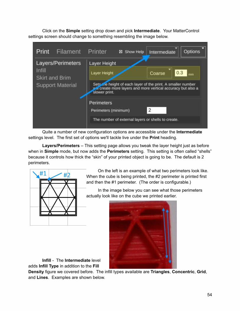
Click on the Simple setting drop down and pick Intermediate. Your MatterControl settings screen should change to something resembling the image below.
Quite a number of new configuration options are accessible under the Intermediate settings level. The first set of options we'll tackle live under the Print heading.
Layers/Perimeters – This setting page allows you tweak the layer height just as before when in Simple mode, but now adds the Perimeters setting. This setting is often called “shells”because it controls how thick the “skin” of your printed object is going to be. The default is 2 perimeters.
On the left is an example of what two perimeters look like. When the cube is being printed, the #2 perimeter is printed first and then the #1 perimeter. (The order is configurable.)
In the image below you can see what those perimeters actually look like on the cube we printed earlier.
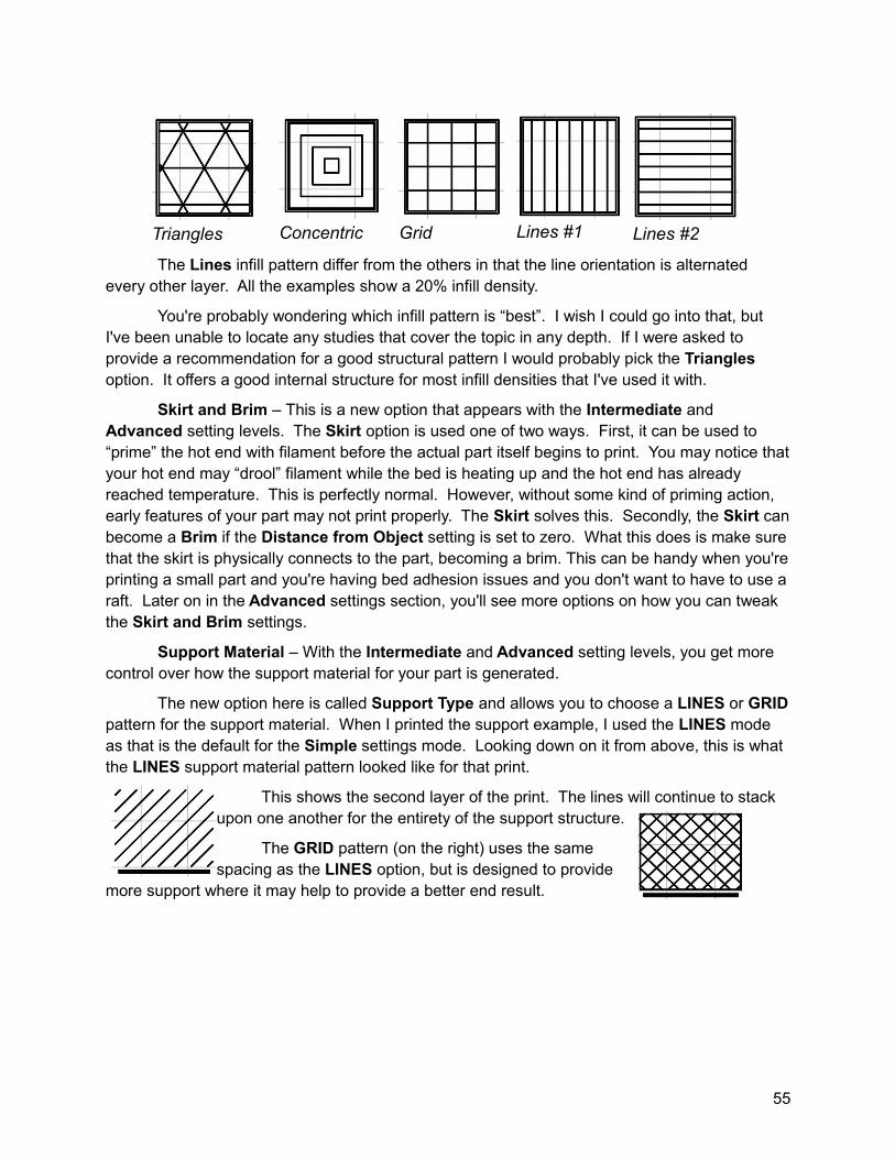
Infill - The Intermediate leveladds Infill Type in addition to the FillDensity figure we covered before. The infill types available are Triangles, Concentric, Grid, and Lines. Examples are shown below.
54
The Lines infill pattern differ from the others in that the line orientation is alternated every other layer. All the examples show a 20% infill density.
You're probably wondering which infill pattern is “best”. I wish I could go into that, but I've been unable to locate any studies that cover the topic in any depth. If I were asked to provide a recommendation for a good structural pattern I would probably pick the Triangles option. It offers a good internal structure for most infill densities that I've used it with.
Skirt and Brim – This is a new option that appears with the Intermediate and Advanced setting levels. The Skirt option is used one of two ways. First, it can be used to “prime” the hot end with filament before the actual part itself begins to print. You may notice thatyour hot end may “drool” filament while the bed is heating up and the hot end has already reached temperature. This is perfectly normal. However, without some kind of priming action, early features of your part may not print properly. The Skirt solves this. Secondly, the Skirt canbecome a Brim if the Distance from Object setting is set to zero. What this does is make surethat the skirt is physically connects to the part, becoming a brim. This can be handy when you'reprinting a small part and you're having bed adhesion issues and you don't want to have to use araft. Later on in the Advanced settings section, you'll see more options on how you can tweak the Skirt and Brim settings.
Support Material – With the Intermediate and Advanced setting levels, you get more control over how the support material for your part is generated.
The new option here is called Support Type and allows you to choose a LINES or GRIDpattern for the support material. When I printed the support example, I used the LINES mode as that is the default for the Simple settings mode. Looking down on it from above, this is what the LINES support material pattern looked like for that print.
This shows the second layer of the print. The lines will continue to stack upon one another for the entirety of the support structure.
The GRID pattern (on the right) uses the samespacing as the LINES option, but is designed to provide
more support where it may help to provide a better end result.
55
Triangles Lines #1Concentric Grid Lines #2
The next new category exposed by the Intermediate setting is called Filament. Under the Intermediate setting, the only option is Filament. This allows you to set three parameters that deal directly with the material you're currently using to print with.
Diameter – This is the diameter of the filament you're using. The more accurate this figure is, the better the quality of your prints. This is because the slicer uses the filament diameter to help calculate the optimum flow rate for the extruder during the print.
In order to get an accurate filament diameter, spool off a meter or so of filament and check it in 10 spots along the length of the material. Record the measurements using a digital micrometer and average the results. That average should go into the Diameter field.
Extruder Temperature – This figure determines the target temperature of the hot end for the material you're printing with. A typical heat range for ABS is 220 to 240C and 190 to 220C for PLA. Other materials will have their own recommended temperature ranges. NEVER,EVER, EXCEED 245C WITH THE STOCK HOT END THAT'S SHIPPED WITH THE ORION!
The reason for this is because of how the stock hot end is designed. It uses a PEEK section (a high-temperature plastic) as the “cold end” of the hot end. This material will begin to fail at 247C. If you need to print with a high-temperature filament such as Nylon, it's highly recommended that you purchase an all-metal hot end.
Bed Temperature – Like the Extruder Temperature the bed temperature is material-dependent. For ABS, a typical heated bed temperature range is between 80 and 100C. For PLA the range is typically 55 to 65C.
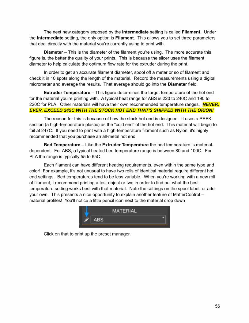
Each filament can have different heating requirements, even within the same type and color! For example, it's not unusual to have two rolls of identical material require different hot end settings. Bed temperatures tend to be less variable. When you're working with a new roll of filament, I recommend printing a test object or two in order to find out what the best temperature setting works best with that material. Note the settings on the spool label, or add your own. This presents a nice opportunity to explain another feature of MatterControl – material profiles! You'll notice a little pencil icon next to the material drop down
Click on that to print up the preset manager.
56
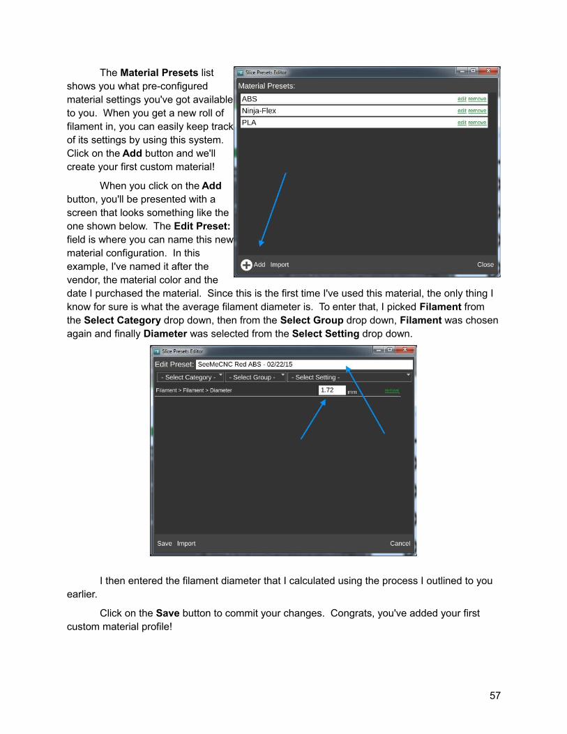
The Material Presets listshows you what pre-configuredmaterial settings you've got availableto you. When you get a new roll offilament in, you can easily keep trackof its settings by using this system.Click on the Add button and we'llcreate your first custom material!
When you click on the Addbutton, you'll be presented with ascreen that looks something like theone shown below. The Edit Preset:field is where you can name this newmaterial configuration. In thisexample, I've named it after thevendor, the material color and thedate I purchased the material. Since this is the first time I've used this material, the only thing I know for sure is what the average filament diameter is. To enter that, I picked Filament from the Select Category drop down, then from the Select Group drop down, Filament was chosenagain and finally Diameter was selected from the Select Setting drop down.
I then entered the filament diameter that I calculated using the process I outlined to you earlier.
Click on the Save button to commit your changes. Congrats, you've added your first custom material profile!
57
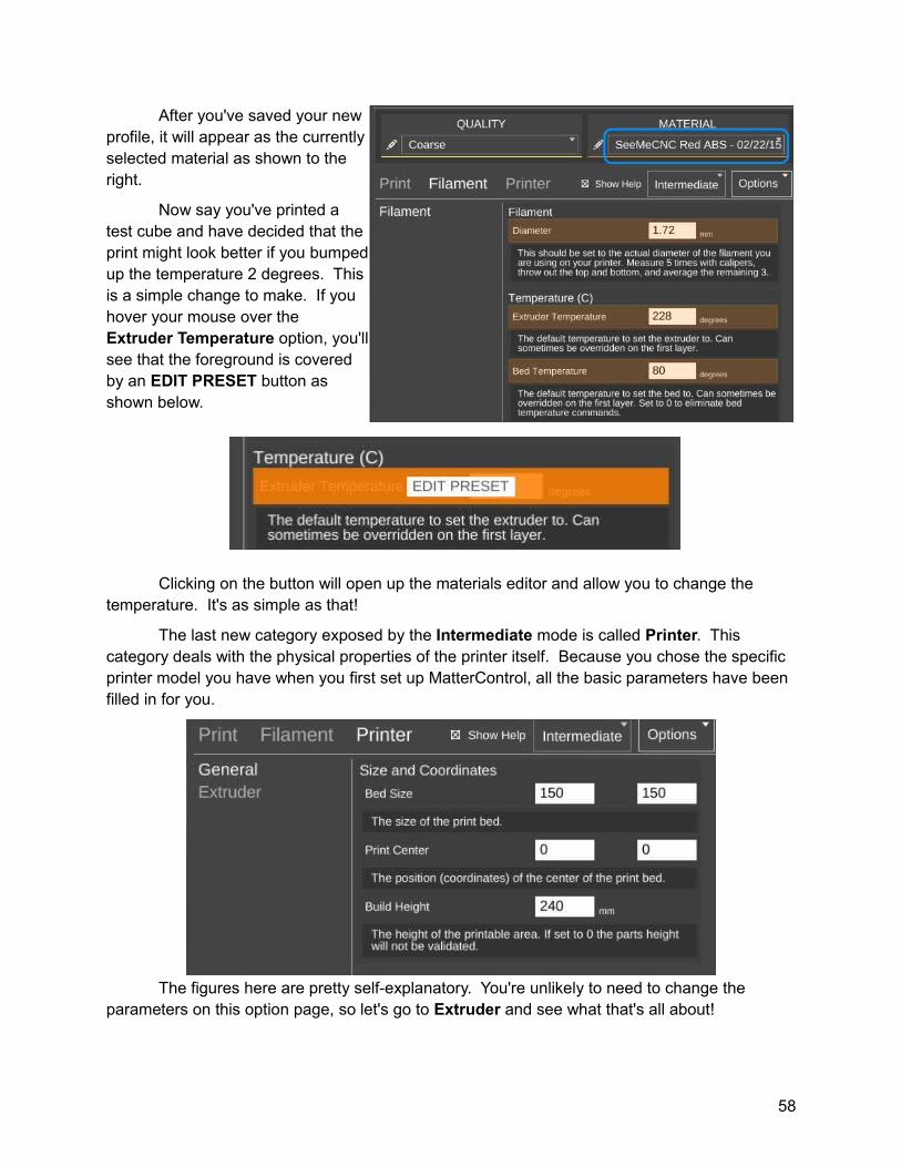
After you've saved your newprofile, it will appear as the currentlyselected material as shown to theright.
Now say you've printed atest cube and have decided that theprint might look better if you bumpedup the temperature 2 degrees. Thisis a simple change to make. If youhover your mouse over the Extruder Temperature option, you'llsee that the foreground is coveredby an EDIT PRESET button asshown below.
Clicking on the button will open up the materials editor and allow you to change the temperature. It's as simple as that!
The last new category exposed by the Intermediate mode is called Printer. This category deals with the physical properties of the printer itself. Because you chose the specific printer model you have when you first set up MatterControl, all the basic parameters have been filled in for you.
The figures here are pretty self-explanatory. You're unlikely to need to change the parameters on this option page, so let's go to Extruder and see what that's all about!
58
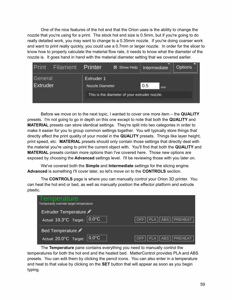
One of the nice features of the hot end that the Orion uses is the ability to change the nozzle that you're using for a print. The stock hot end size is 0.5mm, but if you're going to do really detailed work, you may want to change to a 0.35mm nozzle. If you're doing coarser work and want to print really quickly, you could use a 0.7mm or larger nozzle. In order for the slicer toknow how to properly calculate the material flow rate, it needs to know what the diameter of the nozzle is. It goes hand in hand with the material diameter setting that we covered earlier.
Before we move on to the next topic, I wanted to cover one more item – the QUALITY presets. I'm not going to go in depth on this one except to note that both the QUALITY and MATERIAL presets can store identical settings. They're split into two categories in order to make it easier for you to group common settings together. You will typically store things that directly affect the print quality of your model in the QUALITY presets. Things like layer height, print speed, etc. MATERIAL presets should only contain those settings that directly deal with the material you're using to print the current object with. You'll find that both the QUALITY and MATERIAL presets contain more options than I've covered here. Those new options are exposed by choosing the Advanced settings level. I'll be reviewing those with you later on.
We've covered both the Simple and Intermediate settings for the slicing engine. Advanced is something I'll cover later, so let's move on to the CONTROLS section.
The CONTROLS page is where you can manually control your Orion 3D printer. You can heat the hot end or bed, as well as manually position the effector platform and extrude plastic.
The Temperature pane contains everything you need to manually control the temperatures for both the hot end and the heated bed. MatterControl provides PLA and ABS presets. You can edit them by clicking the pencil icons. You can also enter in a temperature and heat to that value by clicking on the SET button that will appear as soon as you begin typing.
59
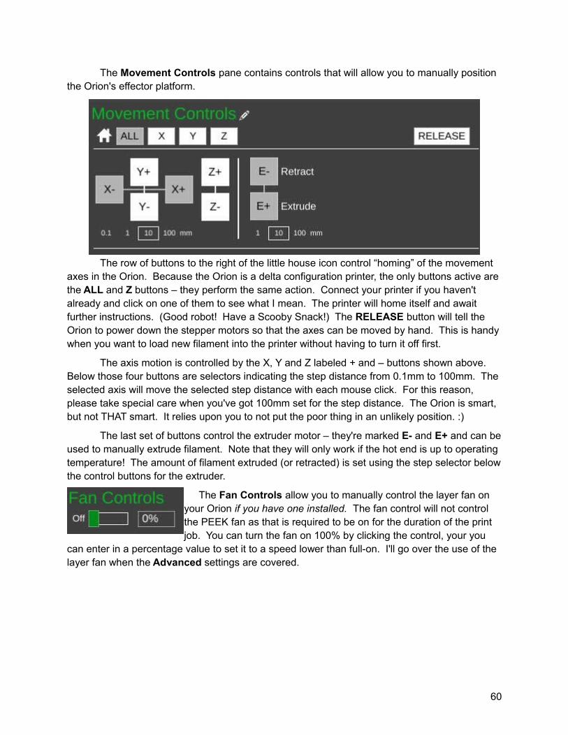
The Movement Controls pane contains controls that will allow you to manually position the Orion's effector platform.
The row of buttons to the right of the little house icon control “homing” of the movement axes in the Orion. Because the Orion is a delta configuration printer, the only buttons active are the ALL and Z buttons – they perform the same action. Connect your printer if you haven't already and click on one of them to see what I mean. The printer will home itself and await further instructions. (Good robot! Have a Scooby Snack!) The RELEASE button will tell the Orion to power down the stepper motors so that the axes can be moved by hand. This is handywhen you want to load new filament into the printer without having to turn it off first.
The axis motion is controlled by the X, Y and Z labeled + and – buttons shown above. Below those four buttons are selectors indicating the step distance from 0.1mm to 100mm. The selected axis will move the selected step distance with each mouse click. For this reason, please take special care when you've got 100mm set for the step distance. The Orion is smart, but not THAT smart. It relies upon you to not put the poor thing in an unlikely position. :)
The last set of buttons control the extruder motor – they're marked E- and E+ and can beused to manually extrude filament. Note that they will only work if the hot end is up to operating temperature! The amount of filament extruded (or retracted) is set using the step selector belowthe control buttons for the extruder.
The Fan Controls allow you to manually control the layer fan on your Orion if you have one installed. The fan control will not control the PEEK fan as that is required to be on for the duration of the print job. You can turn the fan on 100% by clicking the control, your you
can enter in a percentage value to set it to a speed lower than full-on. I'll go over the use of the layer fan when the Advanced settings are covered.
60
MatterControl Basics: Loading and Printing an ObjectWe've previously worked with the small cube that MatterControl provided as an example.
Now we're going to cover loading and slicing an object from start to finish.
For this section, I recommend you head over to http://www.repables.com and find something you'd like to print. I'm going to chose the Orion Key Chain (http://www.repables.com/r/151/) for my example print. You don't have to make the same choice, but pick something geometrically “simple” in order to make the learning process a bit easier.
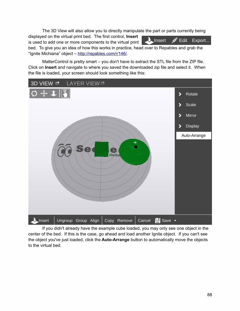
Most (if not all) 3D printer slicing programs can read a file format called “STL”. (You can learn more about this file format, including its origins, here: http://en.wikipedia.org/wiki/STL_%28file_format%29) When you download a file from Repables or one of the other free, online object repositories, you'll often get the file as a zip file. One nice feature of MatterControl is the ability to select a zip file and MatterControl will transparently extract all the files it knows how to read and load them up into your print queue.
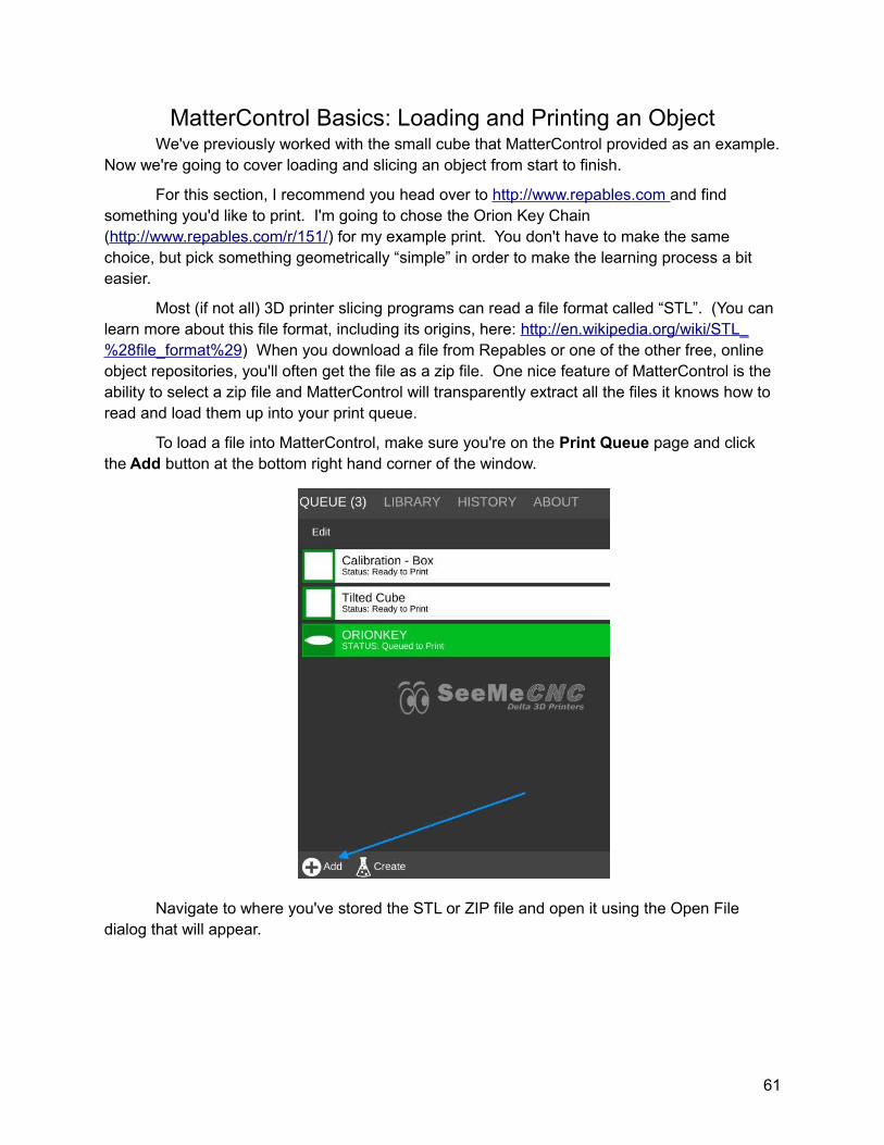
To load a file into MatterControl, make sure you're on the Print Queue page and click the Add button at the bottom right hand corner of the window.
Navigate to where you've stored the STL or ZIP file and open it using the Open File dialog that will appear.
Once you have the object loaded, click on the Advanced Controls button so we can make sure your print settings are the way you want them.
For my print, I've decided to leave the QUALITY setting at Coarse and I'm using the tweaked material values that I set up earlier.
Because the key chain is pretty large, I'm going to scale it down to 75% of it's original size. This is an easy task in MatterControl.
Click on the Edit button as shown above. This will modify the 3D View so the edit controls are visible.
62
Click on the Scale button toaccess the scaling controls. As youcan see, I changed the value to .75or 75% of its original size. Click onthe small up arrow next to the Savebutton at the bottom of the window.This will allow you to save the objectunder a different name if you don'twant to over-write the original.
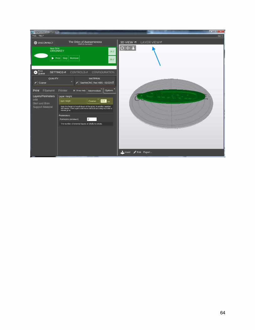
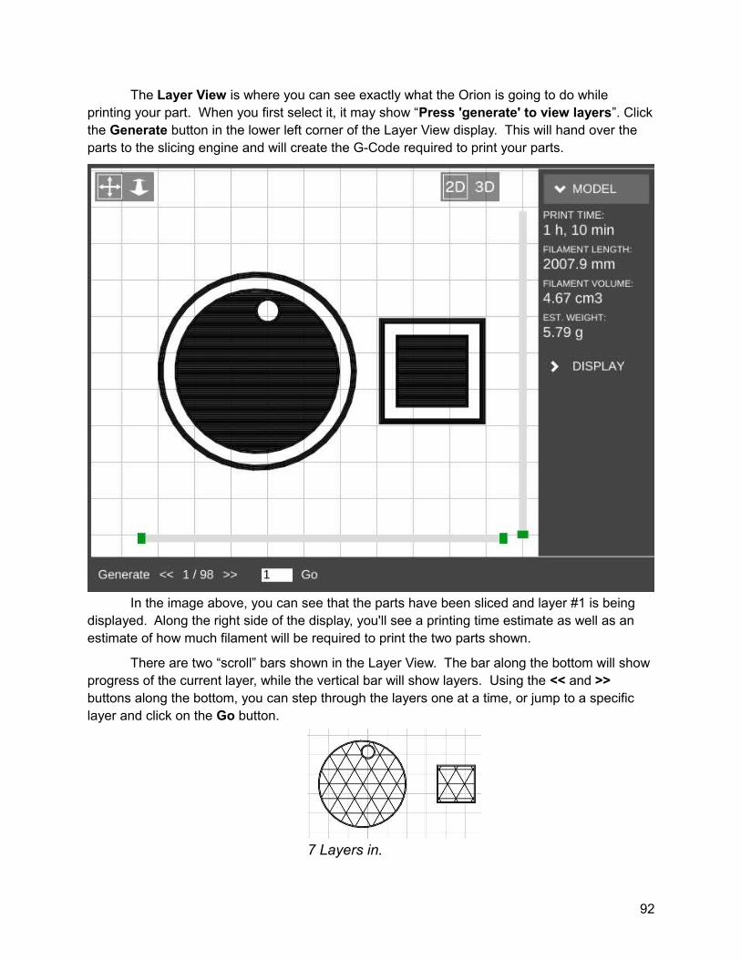
Before we start this print, let's take a second to examine a feature of MatterControl – the Layer View. If you've not sliced this object yet, you'll like see the text “Press 'generate' to view layers”. Go ahead and do that now.
63
64
When it finishes, the layer view will display the first layer of your print job.
You'll notice right off the skirt that I covered previously. It's important to make sure that the hot end is primed by the time it begins to print your part!
At the bottom of the window you'll see some controls that will allow you to either re-slice the object (Generate) or view the individual print layers.
The controls will show you how many layers are on this object as well as what the layer number is that you're currently viewing. You can navigate forward and backward through the layers by using the >> and << buttons. If you want to jump to a specific layer, you can enter it into the box and click Go.
65
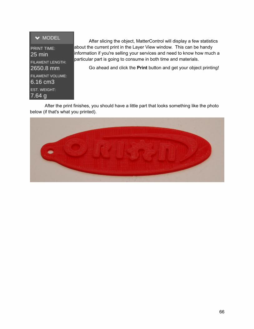
After slicing the object, MatterControl will display a few statistics about the current print in the Layer View window. This can be handy information if you're selling your services and need to know how much a particular part is going to consume in both time and materials.
Go ahead and click the Print button and get your object printing!
After the print finishes, you should have a little part that looks something like the photo below (if that's what you printed).
66
Advanced MatterControl: Configuration MatterControl includes a number of basic configuration options that you can use to set up things like your default slicing engine, change EEPROM settings, etc.
Let's go over each one as they appear on the MatterControl Configuration pane.
MatterControl includes a bed leveling feature that when properly configured, can assist with issues that can arise from an unlevel bed. Note that this will NOT calibrate a delta printer! What it can do is help improve first layer performance on an already calibrated printer.
SeeMeCNC has put together a nice video that illustrates the process quite effectively:
https://www.youtube.com/watch?v=z6ymbr-AMew
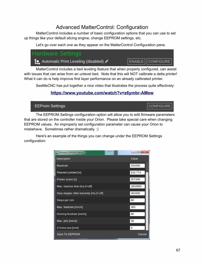
The EEPROM Settings configuration option will allow you to edit firmware parameters that are stored on the controller inside your Orion. Please take special care when changing EEPROM values. An improperly set configuration parameter can cause your Orion to misbehave. Sometimes rather dramatically. :)
Here's an example of the things you can change under the EEPROM Settings configuration:
The Gcode Terminal is where you can directly interact with the firmware on your Orion 3D printer.
When you first open the Gcode Terminal, you'll be presented with a window that looks similar to the one below:
You'll notice that the display will scroll as new information comes in from the Orion. This is how MatterControl is able to continually update things like the temperature displays. In order to be able to use the terminal for basic tasks, you'll need to click on the Filter Output check boxthat's at the upper left corner of the window. This will filter out the telemetry information coming from the Orion's controller and allow you to directly interact with the printer without having the output interleaved with the periodic information that the Orion transmits.
MatterControl provides the ability to remotely monitor your Orion 3D printer from anywhere in the world. To learn more about this service, click on the MORE INFO link in MatterControl.
68
By default, MatterControl will play a bell sound when the current active print job completes. However, you can change this behavior via the Notification Settings configuration screen. You'll be able to configure MatterControl to send you an email or text message when your printer completes a job. Note that this feature is only available when you're using MatterControl to run a print job. If you're printing from the SD card, notification won't be possible.
The Update Notification Feed configuration option allows you to choose which type of release you want to be notified about when there's an update. Stable releases are tested and generally recommended for all users. The Beta release level represents versions of MatterControl that are in a pre-release state, but testing is ongoing. Use this release level if youenjoy assisting the MatterControl software development team find bugs. Last, there is the Alpha release level. This may contain bleeding edge and most certainly lightly tested features. Please only select this level if you're willing to play the part of a guinea pig. :)
This particular configuration option should be pretty self-explanatory. I hope.
69
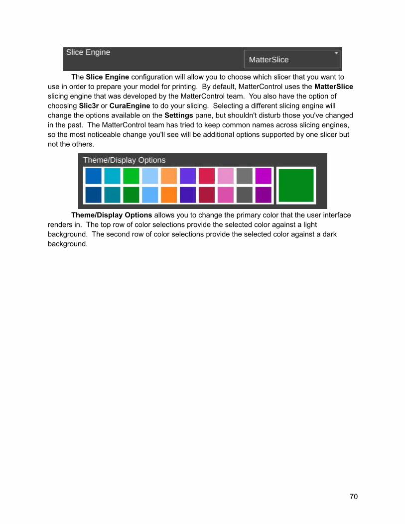
The Slice Engine configuration will allow you to choose which slicer that you want to use in order to prepare your model for printing. By default, MatterControl uses the MatterSlice slicing engine that was developed by the MatterControl team. You also have the option of choosing Slic3r or CuraEngine to do your slicing. Selecting a different slicing engine will change the options available on the Settings pane, but shouldn't disturb those you've changed in the past. The MatterControl team has tried to keep common names across slicing engines, so the most noticeable change you'll see will be additional options supported by one slicer but not the others.
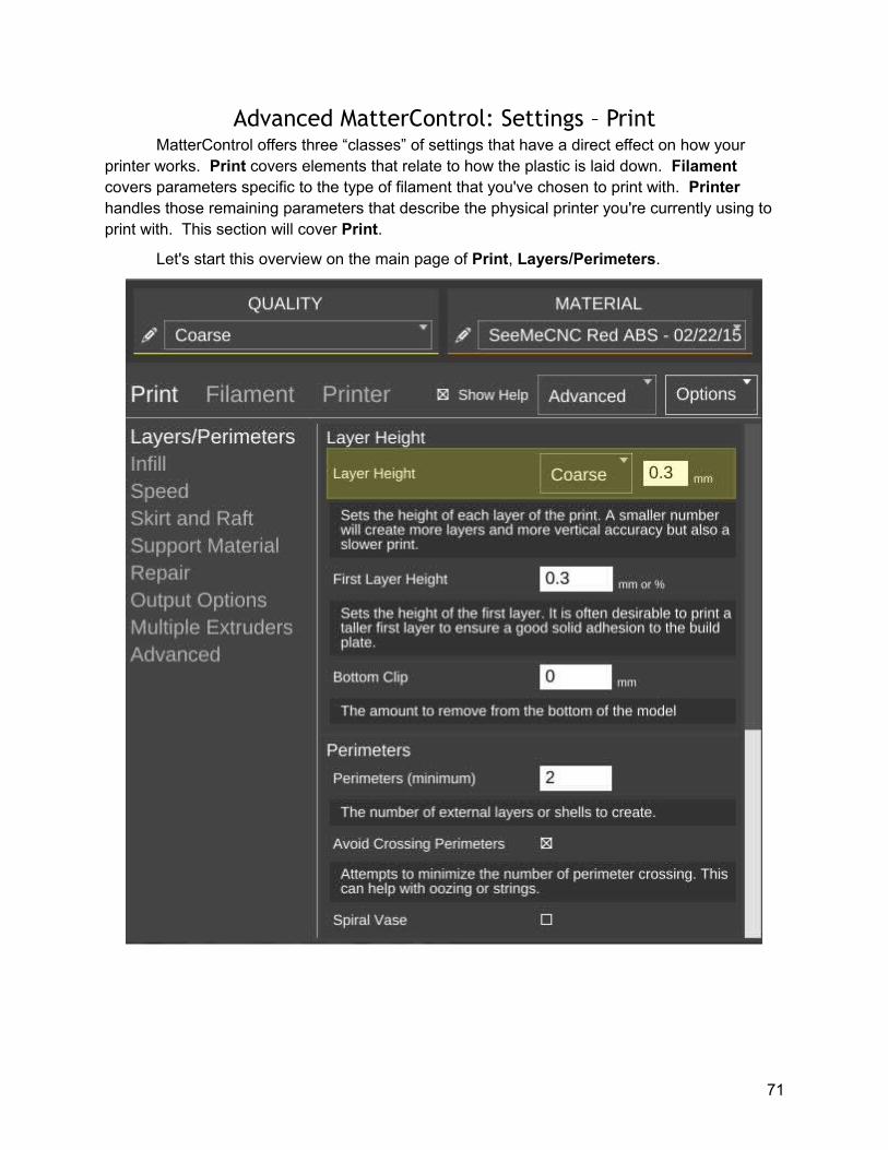
Theme/Display Options allows you to change the primary color that the user interface renders in. The top row of color selections provide the selected color against a light background. The second row of color selections provide the selected color against a dark background.
70
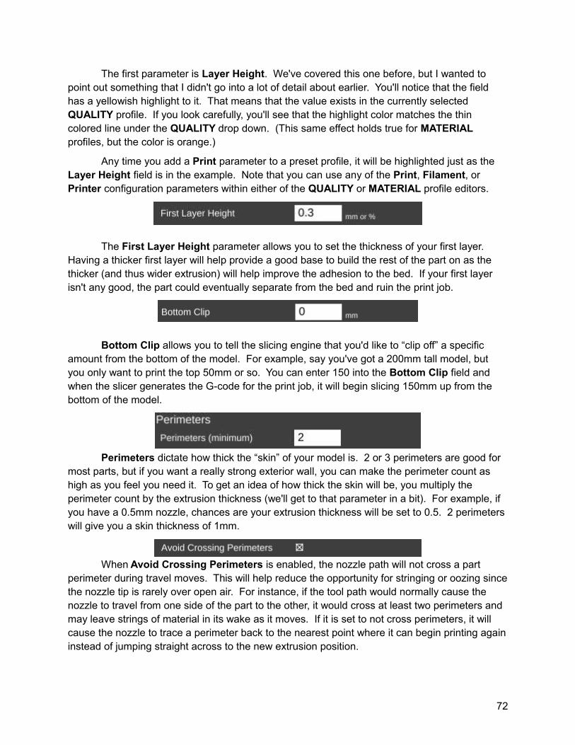
Advanced MatterControl: Settings – Print MatterControl offers three “classes” of settings that have a direct effect on how your printer works. Print covers elements that relate to how the plastic is laid down. Filament covers parameters specific to the type of filament that you've chosen to print with. Printer handles those remaining parameters that describe the physical printer you're currently using to print with. This section will cover Print.
Let's start this overview on the main page of Print, Layers/Perimeters.
71
The first parameter is Layer Height. We've covered this one before, but I wanted to point out something that I didn't go into a lot of detail about earlier. You'll notice that the field has a yellowish highlight to it. That means that the value exists in the currently selected QUALITY profile. If you look carefully, you'll see that the highlight color matches the thin colored line under the QUALITY drop down. (This same effect holds true for MATERIAL profiles, but the color is orange.)
Any time you add a Print parameter to a preset profile, it will be highlighted just as the Layer Height field is in the example. Note that you can use any of the Print, Filament, or Printer configuration parameters within either of the QUALITY or MATERIAL profile editors.
The First Layer Height parameter allows you to set the thickness of your first layer. Having a thicker first layer will help provide a good base to build the rest of the part on as the thicker (and thus wider extrusion) will help improve the adhesion to the bed. If your first layer isn't any good, the part could eventually separate from the bed and ruin the print job.
Bottom Clip allows you to tell the slicing engine that you'd like to “clip off” a specific amount from the bottom of the model. For example, say you've got a 200mm tall model, but you only want to print the top 50mm or so. You can enter 150 into the Bottom Clip field and when the slicer generates the G-code for the print job, it will begin slicing 150mm up from the bottom of the model.
Perimeters dictate how thick the “skin” of your model is. 2 or 3 perimeters are good for most parts, but if you want a really strong exterior wall, you can make the perimeter count as high as you feel you need it. To get an idea of how thick the skin will be, you multiply the perimeter count by the extrusion thickness (we'll get to that parameter in a bit). For example, if you have a 0.5mm nozzle, chances are your extrusion thickness will be set to 0.5. 2 perimeters will give you a skin thickness of 1mm.
When Avoid Crossing Perimeters is enabled, the nozzle path will not cross a part perimeter during travel moves. This will help reduce the opportunity for stringing or oozing sincethe nozzle tip is rarely over open air. For instance, if the tool path would normally cause the nozzle to travel from one side of the part to the other, it would cross at least two perimeters and may leave strings of material in its wake as it moves. If it is set to not cross perimeters, it will cause the nozzle to trace a perimeter back to the nearest point where it can begin printing againinstead of jumping straight across to the new extrusion position.
72
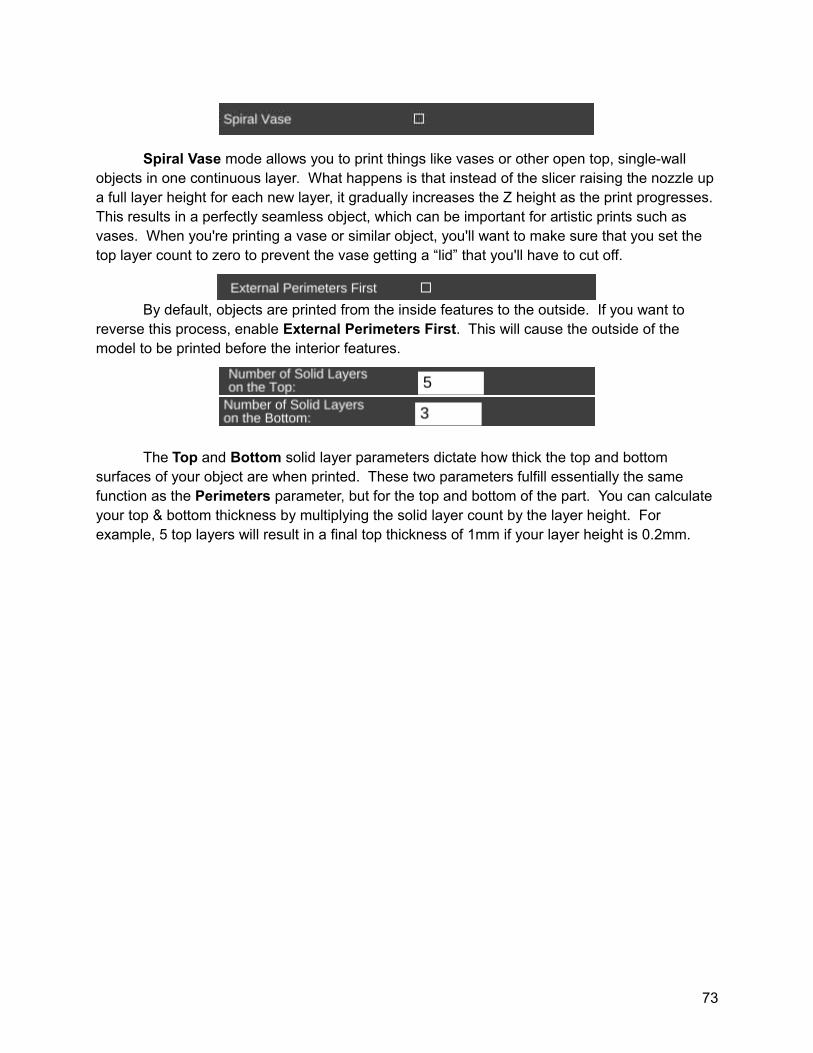
Spiral Vase mode allows you to print things like vases or other open top, single-wall objects in one continuous layer. What happens is that instead of the slicer raising the nozzle up a full layer height for each new layer, it gradually increases the Z height as the print progresses. This results in a perfectly seamless object, which can be important for artistic prints such as vases. When you're printing a vase or similar object, you'll want to make sure that you set the top layer count to zero to prevent the vase getting a “lid” that you'll have to cut off.
By default, objects are printed from the inside features to the outside. If you want to reverse this process, enable External Perimeters First. This will cause the outside of the model to be printed before the interior features.
The Top and Bottom solid layer parameters dictate how thick the top and bottom surfaces of your object are when printed. These two parameters fulfill essentially the same function as the Perimeters parameter, but for the top and bottom of the part. You can calculate your top & bottom thickness by multiplying the solid layer count by the layer height. For example, 5 top layers will result in a final top thickness of 1mm if your layer height is 0.2mm.
73
The next page in Print is called Infill and covers how the interior of your part is filled. While I covered Fill Density and Infill Type earlier, the Advanced mode adds two new parameters.
The Starting Angle parameter allows you to control the orientation of the infill. For example, an infill type of GRID with a starting angle of zero degrees is going to look like this:
Now if you change the starting angle to 45 degrees, you'll end up with an infill pattern that looks like the example below.
Note that changing the starting anglewill also change the angle in which the topand bottom layers are printed. You can see this in the image below – this shows the second layer as it would be printed.
Infill Overlap is used to adjust how well the infill pattern attaches to the inside perimeter of the part. A good infill will have a solid connection to the inside perimeter of your part, and the structural integrity of your part depends on this.
74
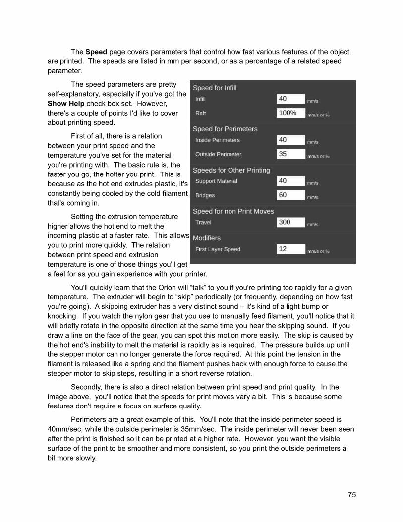
The Speed page covers parameters that control how fast various features of the object are printed. The speeds are listed in mm per second, or as a percentage of a related speed parameter.
The speed parameters are prettyself-explanatory, especially if you've got the Show Help check box set. However,there's a couple of points I'd like to coverabout printing speed.
First of all, there is a relationbetween your print speed and thetemperature you've set for the materialyou're printing with. The basic rule is, thefaster you go, the hotter you print. This isbecause as the hot end extrudes plastic, it'sconstantly being cooled by the cold filamentthat's coming in.
Setting the extrusion temperaturehigher allows the hot end to melt theincoming plastic at a faster rate. This allowsyou to print more quickly. The relationbetween print speed and extrusiontemperature is one of those things you'll geta feel for as you gain experience with your printer.
You'll quickly learn that the Orion will “talk” to you if you're printing too rapidly for a given temperature. The extruder will begin to “skip” periodically (or frequently, depending on how fast you're going). A skipping extruder has a very distinct sound – it's kind of a light bump or knocking. If you watch the nylon gear that you use to manually feed filament, you'll notice that itwill briefly rotate in the opposite direction at the same time you hear the skipping sound. If you draw a line on the face of the gear, you can spot this motion more easily. The skip is caused by the hot end's inability to melt the material is rapidly as is required. The pressure builds up until the stepper motor can no longer generate the force required. At this point the tension in the filament is released like a spring and the filament pushes back with enough force to cause the stepper motor to skip steps, resulting in a short reverse rotation.
Secondly, there is also a direct relation between print speed and print quality. In the image above, you'll notice that the speeds for print moves vary a bit. This is because some features don't require a focus on surface quality.
Perimeters are a great example of this. You'll note that the inside perimeter speed is 40mm/sec, while the outside perimeter is 35mm/sec. The inside perimeter will never been seenafter the print is finished so it can be printed at a higher rate. However, you want the visible surface of the print to be smoother and more consistent, so you print the outside perimeters a bit more slowly.
75
The last bit about speed settings I want to cover is the first layer speed. You'll see that it's really slow. The reason for this is that while hot plastic loves to stick to hot plastic, hot plasticdoesn't like sticking to other things as much. By going slowly on the first layer, you're giving the material time to get a good grip on the surface of the bed. This is known as “part adhesion”. When a part comes unstuck from the bed during a print, it's ruined. This isn't so bad when you're five minutes into a print, but you'll be ready to flip a table when it happens 18 hours into a19 hour print.
The Skirt and Raft page covers settings that control how the hot end is primed at the beginning of a print job as well as features that help the part stick to the bed.
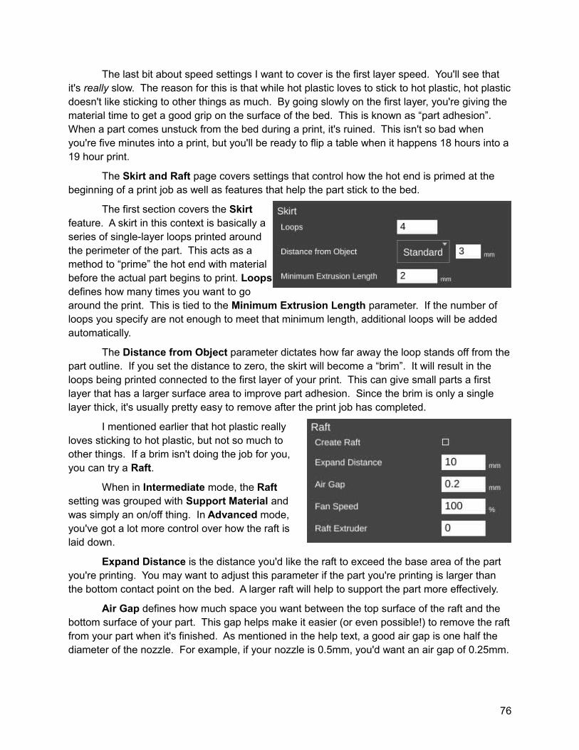
The first section covers the Skirtfeature. A skirt in this context is basically aseries of single-layer loops printed aroundthe perimeter of the part. This acts as amethod to “prime” the hot end with materialbefore the actual part begins to print. Loopsdefines how many times you want to goaround the print. This is tied to the Minimum Extrusion Length parameter. If the number of loops you specify are not enough to meet that minimum length, additional loops will be added automatically.
The Distance from Object parameter dictates how far away the loop stands off from thepart outline. If you set the distance to zero, the skirt will become a “brim”. It will result in the loops being printed connected to the first layer of your print. This can give small parts a first layer that has a larger surface area to improve part adhesion. Since the brim is only a single layer thick, it's usually pretty easy to remove after the print job has completed.
I mentioned earlier that hot plastic reallyloves sticking to hot plastic, but not so much toother things. If a brim isn't doing the job for you,you can try a Raft.
When in Intermediate mode, the Raftsetting was grouped with Support Material andwas simply an on/off thing. In Advanced mode,you've got a lot more control over how the raft islaid down.
Expand Distance is the distance you'd like the raft to exceed the base area of the part you're printing. You may want to adjust this parameter if the part you're printing is larger than the bottom contact point on the bed. A larger raft will help to support the part more effectively.
Air Gap defines how much space you want between the top surface of the raft and the bottom surface of your part. This gap helps make it easier (or even possible!) to remove the raftfrom your part when it's finished. As mentioned in the help text, a good air gap is one half the diameter of the nozzle. For example, if your nozzle is 0.5mm, you'd want an air gap of 0.25mm.
76
If your Orion is equipped with a layer cooling fan, you can use the Fan Speed setting to cool the raft as it's being printed. This is typically only used when printing with PLA.
If you've added a second extruder to your Orion, you can specify which one should be used for rafts by setting the Raft Extruder value to the index of the extruder you want to use. If you don't have multiple extruders, you can leave this set to zero.
The Support Material page provides detailed settings on the use of support material if the part you're printing requires it. While I covered the basics of support earlier, I'm going to get a bit more in-depth on it here.
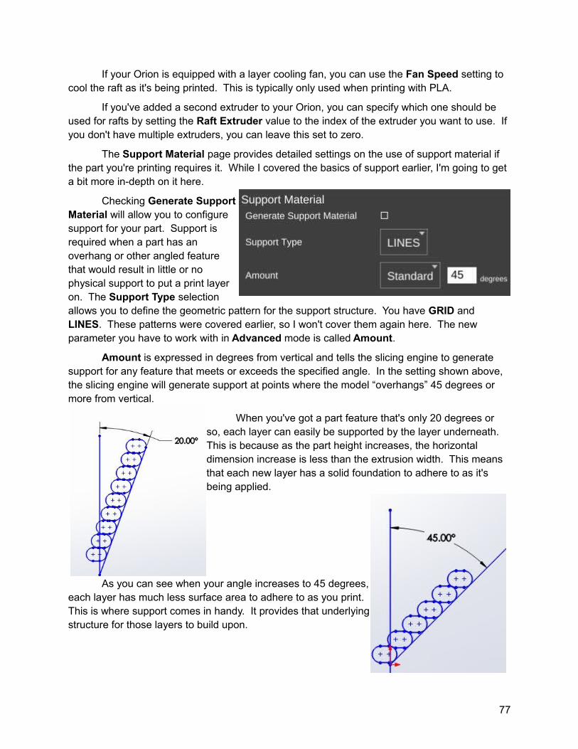
Checking Generate SupportMaterial will allow you to configuresupport for your part. Support isrequired when a part has anoverhang or other angled featurethat would result in little or nophysical support to put a print layeron. The Support Type selectionallows you to define the geometric pattern for the support structure. You have GRID and LINES. These patterns were covered earlier, so I won't cover them again here. The new parameter you have to work with in Advanced mode is called Amount.
Amount is expressed in degrees from vertical and tells the slicing engine to generate support for any feature that meets or exceeds the specified angle. In the setting shown above, the slicing engine will generate support at points where the model “overhangs” 45 degrees or more from vertical.
When you've got a part feature that's only 20 degrees or so, each layer can easily be supported by the layer underneath. This is because as the part height increases, the horizontal dimension increase is less than the extrusion width. This means that each new layer has a solid foundation to adhere to as it's being applied.
As you can see when your angle increases to 45 degrees,each layer has much less surface area to adhere to as you print.This is where support comes in handy. It provides that underlyingstructure for those layers to build upon.
77
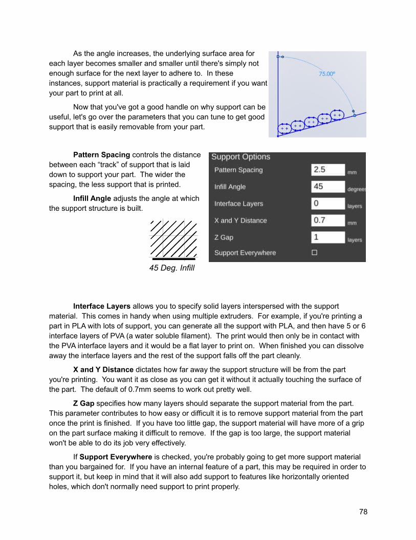
As the angle increases, the underlying surface area foreach layer becomes smaller and smaller until there's simply notenough surface for the next layer to adhere to. In theseinstances, support material is practically a requirement if you wantyour part to print at all.
Now that you've got a good handle on why support can beuseful, let's go over the parameters that you can tune to get goodsupport that is easily removable from your part.
Pattern Spacing controls the distancebetween each “track” of support that is laiddown to support your part. The wider thespacing, the less support that is printed.
Infill Angle adjusts the angle at whichthe support structure is built.
Interface Layers allows you to specify solid layers interspersed with the support material. This comes in handy when using multiple extruders. For example, if you're printing a part in PLA with lots of support, you can generate all the support with PLA, and then have 5 or 6interface layers of PVA (a water soluble filament). The print would then only be in contact with the PVA interface layers and it would be a flat layer to print on. When finished you can dissolve away the interface layers and the rest of the support falls off the part cleanly.
X and Y Distance dictates how far away the support structure will be from the part you're printing. You want it as close as you can get it without it actually touching the surface of the part. The default of 0.7mm seems to work out pretty well.
Z Gap specifies how many layers should separate the support material from the part. This parameter contributes to how easy or difficult it is to remove support material from the part once the print is finished. If you have too little gap, the support material will have more of a grip on the part surface making it difficult to remove. If the gap is too large, the support material won't be able to do its job very effectively.
If Support Everywhere is checked, you're probably going to get more support material than you bargained for. If you have an internal feature of a part, this may be required in order tosupport it, but keep in mind that it will also add support to features like horizontally oriented holes, which don't normally need support to print properly.
78
45 Deg. Infill
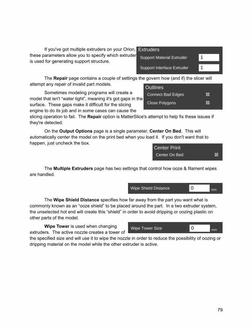
If you've got multiple extruders on your Orion,these parameters allow you to specify which extruderis used for generating support structure.
The Repair page contains a couple of settings the govern how (and if) the slicer will attempt any repair of invalid part models.
Sometimes modeling programs will create amodel that isn't “water tight”, meaning it's got gaps in thesurface. These gaps make it difficult for the slicingengine to do its job and in some cases can cause theslicing operation to fail. The Repair option is MatterSlice's attempt to help fix these issues if they're detected.
On the Output Options page is a single parameter, Center On Bed. This will automatically center the model on the print bed when you load it. If you don't want that to happen, just uncheck the box.
The Multiple Extruders page has two settings that control how ooze & filament wipes are handled.
The Wipe Shield Distance specifies how far away from the part you want what is commonly known as an “ooze shield” to be placed around the part. In a two extruder system, the unselected hot end will create this “shield” in order to avoid dripping or oozing plastic on other parts of the model.
Wipe Tower is used when changingextruders. The active nozzle creates a tower ofthe specified size and will use it to wipe the nozzle in order to reduce the possibility of oozing or dripping material on the model while the other extruder is active.
79
The last page on the Printtab is called Advanced.
The Advance page currentlyonly has the Extrusion Widthsection.
The First Layer parameter allows you to specify the extrusion width of the first layer. A first layer width that's larger can help with how the material adheres to the bed. You can specifyit as either an actual width, or as a percentage of the normal extrusion with (typically the same as the nozzle diameter).
Support Material allows you to specify how wide you want the extrusion to be for the support structure if you're using it.
80
Advanced MatterControl: Settings – Filament The Filament tab allows you to change parameters that deal with the current filament you're printing with. The Filament page is divided into three categories; Filament, Temperature, and Retraction.
The filament Diameter parameter tells theslicing engine the size of the material you'reprinting with. When starting a new roll of material,you should pull off about 2 meters of material andcheck it in 10 spots along the length using a digitalcaliper. Average those samples and plug the result into the Diameter field. This is a good way of getting a good estimate of the material you're actually using. This allows the slicing engine todeliver more consistent results instead of depending on the generic size of the material.
You'll notice that the Diameter field is highlighted in orange. This means that the parameter is part of a predefined material configuration. When using a new spool of material forthe first time, it's a good idea to create a new profile for it when you're taking the sample measurements of the diameter. A good rule of thumb is to include the date you started using thefilament as part of the material profile name. Note the date on the spool label if it has one and add one if it doesn't. This will help you track individual spools of the same color and manufacturer.
The Extrusion Multiplier parameter allows you to tweak the flow rate of the material coming out of the hot end. A basic rule of thumb on this is to restrict the max value to 1.1 and the minimum value to 0.9. Note that these aren't hard limits but are simply a guideline to utilize until you're familiar with the effects this parameter has on print jobs.
The Extruder Temperature is thetemperature for the hot end, BedTemperature is the temperature for theheated bed. As you can see, both of theseare part of the currently selected materialprofile. Each material class has a generaltemperature range for the hot end. For example, ABS extrusion temperatures can range from 195 to 240C. PLA likes anywhere from 180 to 215. The specific temperature that your material works best at varies by manufacturer and chemical blend. It's not unusual to see different “sweet spot” temperatures among identical colors of material, even with the same manufacturer.
The Bed Temperature parameter typically has a lot less of a range than the extrusion temperature does. A good rule of thumb here is 55-60C for PLA and 80-100C for ABS.
81
Retraction covers how the slicer “retracts” the filament during travel operations where it's not actually laying down plastic. Goodretraction settings help keep your part free oflittle strings and blobs during printing.
Length on Move specifies how muchfilament will be backed out of the hot end duringa non-printing move.
Length on Tool Change is specific tomulti-extruder systems. If the slicer is changingto a new extruder, it will retract the material out ofthe current hot end by this much. This works inconjunction with wipe towers and wipe shields.
Speed dictates how fast the extruder drive will pull the filament out of the hot end. Higherspeeds can assist in preventing already-melted plastic from oozing or leaving strings on the partbeing printed. It also controls how fast the filament will be returned to the hot end when the non-printing move has completed.
Z-Lift is used to lift the nozzle off of the part as each retract finishes. This can help prevent blobbing.
Minimum Travel Requiring Retraction is used to prevent retractions during very short moves when retraction isn't really necessary. When executing a non-printing move, the nozzle will have to travel at least this distance in order to trigger a retraction action.
Finally, Minimum Extrusion Requiring Retraction specifies how much filament must be extruded before a retraction operation is permitted. This helps prevent instances where a retraction operation would occur before the hot end had the opportunity to actually extrude material.
The Cooling page covers parameters relating to layer cooling.
Enable Extruder Lift if set, will cause the hot end tolift up from the part to allow cooling.
The Fan Speed section controls howand when the cooling layer fan is used.
Minimum and Maximum Fan Speedcontrols the lower and upper limits of how fastyou want the fan to go when it's enabled. If youspecify a minimum speed, the slicing enginewill automatically vary the speed of the fanbetween the min & max values, depending onthe location being printed. For larger parts, theslicing engine may run the fan more slowly than it would for smaller parts.
82
Bridging Fan Speed covers the speed that the fan should run at when the slicer is creating a filament bridge. A bridge is basically a free-hanging length of filament with no supportbelow it. Some materials like PLA form excellent bridges if cooled while being extruded.
Disable Fan For The First n Layers allows you to make sure that the fan isn't activated during the crucial first few layers of a print. You typically don't use the fan for at least the first two layers in order to help ensure good bed adhesion.
Cooling Thresholds allow you to slowthe print speed down during a print if needed.If the current layer will require more than thespecified time to print, the slicing engine willautomatically slow the print speed down tomeet this goal. This can be important becauseif you don't use a fan, a layer will need time to radiate its excess heat before the next layer is applied. If the material isn't cooled, or given time to cool via radiation, heat can build up in the underlying layers and cause curling and other undesirable effects.
Minimum Print Speed can be used to ensure that the printer doesn't slow down TOO much, which can cause it's own heating problems. For example, if you're printing too slowly, thepresence of the nozzle moving over the surface can cause heating to areas adjacent to the nozzle tip which can cause blobbing or layer deformation.
Note that none of the fan options will come into effect unless you've enabled the operation of the fan. I'll cover that in the next section.
83
Advanced MatterControl: Settings – Printer The Printer section covers items that are specific to the printer being used for the current print job.
The General page coversparameters that describe themechanical features of the printer.
The Bed Size fields coverthe width and length of the bed.Since the Orion has a round bed,you'll see that both figures are thesame, the Print Center has beenset to 0,0 (the center of the circle)and the Bed Shape has been set to circular.
The Build Height parameter should be set to the highest practical build height. In the case of the Orion, this is set to 240mm.
Z Offset can be used if you want to set a specific adjustment to the z position of the G-code when it's created by the slicing engine.
The Bed Shape parameter dictates what bed type is shown in the 3D viewer.
The Hardware section allows you to specifywhat features are installed on your Orion.
Has Fan, when checked will allow the slicingengine to control the layer cooling fan.
Has Hardware Leveling should be set ifyou've added a mechanical depth probe for levelingthe bed on your Orion.
Has Heated Bed should be checked for theOrion. This allows the slicing engine to control theheat of the bed.
Has SD Card Reader should be checked for the Orion. This allows MatterControl to save STL and G-Code directly to the SD card if it's installed in the Orion.
For a stock Orion, Extruder Count should be set to 1. If you add an additional extruder in the future, you can tell the slicing engine about it here.
Share Temperature is used when utilizing multiple extruders that share the same heat source.
84
The Firmware section allows you totell the slicing engine about the firmwareyou're using with your Orion.
Z Can Be Negative can be checked ifthe firmware you're using on your Orion willaccept Z positions below zero. Leave this unchecked if you're using the stock Orion firmware.
G-Code Output specifies what “flavor” of G-Code should be created by the slicing engine. For the Orion, this should be set to REPRAP.
The next page is called CustomG-Code and allows you to customize thecode sent for five different print events.Unless you're familiar with what the listedG and M codes do, please don't modifythe defaults shown.
Start G-Code is inserted into theG-Code output right after the temperaturesetting. If you have the commands to setthe temperatures in this section, theywon't be generated outside of this section.You can also include values from othersections such as “first_layer_temperature”
End G-Code is inserted into theoutput at the very end, after all printoperations have been completed.
Pause G-Code is sent when theOrion is paused during a print.
Resume G-Code is sent when theOrion is resumed.
Cancel G-Code is sent when youcancel a print job from MatterControl
85
The last page for the Printer tab is called Extruder. This page allows you to configure each extruder you have installed in your Orion.
Nozzle Diameter specifiesthe diameter of the currentlyinstalled nozzle in the hot end.
Extruder Offset allows youto specify the offset from the centerof the effector platform in the Orion. This parameter is only used in multi-extruder configurations.
The last feature I'd like to cover can be found here:
The Options control allows you to import and exportconfigurations. This can be handy when you want to share your slicing engine settings with others, or import settings from other sources.
86
Using the 3D View and Layer View The 3D View will show you the part that will be printed when you hit the Print button. TheLayer View is used to inspect how your part will be printed, one layer at a time.
The 3D View will allow you to view your model in pretty much any orientation you'd like. The view orientation is controlled one of two ways. You can select one of the movement icons
in conjunction with the left mouse button. The first icon will allow you to “free rotate” the model and build platform. The second icon will allow you to
move the part and build platform left and right, as well as up and down. The third icon will allow you to zoom in and out.
You can use the mouse alone as well. Holding down the left mouse button will allow youto “free rotate” the model and bed. Holding down the mouse wheel will allow you to move left and right as well as up and down. Spinning the mouse wheel will zoom in and out.
87
The 3D View will also allow you to directly manipulate the part or parts currently being displayed on the virtual print bed. The first control, Insertis used to add one or more components to the virtual printbed. To give you an idea of how this works in practice, head over to Repables and grab the “Ignite Michiana” object – http://repables.com/r/146/.
MatterControl is pretty smart – you don't have to extract the STL file from the ZIP file. Click on Insert and navigate to where you saved the downloaded zip file and select it. When the file is loaded, your screen should look something like this:
If you didn't already have the example cube loaded, you may only see one object in the center of the bed. If this is the case, go ahead and load another Ignite object. If you can't see the object you've just loaded, click the Auto-Arrange button to automatically move the objects to the virtual bed.
You'll end up with something similar to the figure below after clicking on Auto-Arrange.
The blue arrow points to a tiny icon that indicates which is the currently selected object.
In order to move an object around manually, you'll need to make sure that the “picker” icon has been selected.
Once you've clicked on that icon, you'll be able to move the parts any where you like. However,be aware that the software will allow you to move the objects outside the confines of the virtual bed and they will not be printable outside of those limits.
You'll notice that you've got some new controls along the bottom of the 3D View window – Ungroup, Group, Align, Copy, Remove, Cancel, and Save.
The Ungroup button will undo the “grouping” done by the Group and Align buttons.
Clicking Group will virtually connect all the objects on the print bed so they can be moved all at the same time.
The Align button has the same effect as the Auto-Arrange button, but the resulting group of objects are not centered on the virtual print bed.
Copy allows you to create duplicates of objects that are on the print bed as shown below. Make sure that you've got the object you want to copy selected before you click the Copy button.
89
Be aware that if you've got your objects grouped, clicking on Copy will result in the entiregroup being copied.
The Remove button works as you'd expect. Select an object and click Remove to remove it from the virtual build surface.
Cancel will discard any changes you've made so far and Save will allow you to save the state of the virtual print surface. Saving your work saves it to the print queue. If you'd like to save your work as a combined STL file
While you're in edit mode, there's a series of commands thatbecome available along the right edge of the 3D View pane.
Unlike normal manual positioning, the Rotate function allows you to specify the exactrotation of the object along its X, Y, and Z axes.
In order to change the orientation of theobject, simply enter the value you want in the Degrees field and then click the axis you want toapply that value to. Below is an example of whatthe example cube looks like after rotating it 45degrees along its X axis.
Being able to re-orient the part on the build surface can be handy to have, especially if you're dealing with a part that was saved in a position that didn't lend itselfto easy 3D printing.
Clicking Align to Bed will automatically orient the nearest flat surface to the virtual build platform.
The Scale function will allow you to change the width, height and length of the part or parts currently on the virtual build platform.
The Ratio field allows you to shrink or grow an entire model by a specific percentage. For example, if you were to change the Ratio from 1to 1.5, you'd see this:
Become this:
90
The scaling operation made the cube 150% larger than the original. The X, Y, and Z fields allow you to specify exact dimensions. However, as long as the Lock Ratio field is checked, any change made to those fields will adjust the others to maintain the same ratio.
The Mirror function will simply allow you to “mirror” the object along any of the three axes. Note that mirroring the Z axis will flip the part upside down, so be careful.
The Display function allows you to modify how the 3D View pane operates. Show Print Bed is pretty obvious. Uncheck it and see what happens! Shop Print Area is handy when you want to see exactly how much space your parts are going to take up. When selected, it will display a shadowed cylinder that encapsulates the maximum bed diameter and print height, as show below.
The Shaded, Outlines, and Polygons options allow you to change howyour objects are drawn. By default the Shaded option is checked. For most partsthis is fine, but if you'd like to see detail thatthe solid shading can hide, click Outlines.Models used for 3D printing are built out ofa few up to many thousands of polygons.If you'd like to see what the polygons looklike that make up your model, click the Polygons option.
I find that the Outlines display option is the most useful as it makes part detail much more easy to see.
91
ShadedOutlines
Polygons
The Layer View is where you can see exactly what the Orion is going to do while printing your part. When you first select it, it may show “Press 'generate' to view layers”. Clickthe Generate button in the lower left corner of the Layer View display. This will hand over the parts to the slicing engine and will create the G-Code required to print your parts.
In the image above, you can see that the parts have been sliced and layer #1 is being displayed. Along the right side of the display, you'll see a printing time estimate as well as an estimate of how much filament will be required to print the two parts shown.
There are two “scroll” bars shown in the Layer View. The bar along the bottom will show progress of the current layer, while the vertical bar will show layers. Using the << and >> buttons along the bottom, you can step through the layers one at a time, or jump to a specific layer and click on the Go button.
92
7 Layers in.
The Layer View will also allow you to see the layers in 3D. Just click the 3D icon at the upper right corner of the display window to see your layers in 3D! The display can be moved around in the same manner as that shown for the 3D View.
The Layer View will also display other information about the printing process, such as non-printing movement, retractions, etc. Click on the Display button to the right of the display to open up those display options.
Grid hides or displays the virtual print surface.
Moves will show you the path the print head takes when it's notprinting, as shown by the light green lines in the image below.
Retractions show the points in the print where the extruder is going to retract filament from the hot end. This is done either during a non-printing move, or when changing extruders.
The red and blue points in the image to theright show where the retractions are happening.
Red shows the retract operation while theblue color shows the resume/extrude.
93
7 Layers in, 3D view.
Speeds will color the layers based on how fast the layer is printed.
The Extrusion option will thicken the lines used to draw the layers in order to give a more accurate visual representation of what the actual print layer will look like when printed.
Finally, Sync to Print will allow you to follow the print process using the Layer View. As the Orion prints your part, you'll see a real-time reflection of those moves. It's a pretty nice feature.
94
A Strategy for Successful (and Great!) Prints Michael Hackney is one our forum moderators over at the SeeMeCNC forum and he's been gracious enough to allow me to publish his wonderful guide for getting the most out of your SeeMeCNC 3D printer. You can find his original thread here: http://forum.seemecnc.com/viewtopic.php?f=36&t=7361
Some of the links below reference part files that are stored on the forum itself. You may need to create a forum account to reach them. I highly recommend doing this whether or not you need the files. The SeeMeCNC is an excellent resource with a vibrant, helpful and very newbie-friendly community.
I've watched folks struggle to achieve the results they want/expect here for several years- heck, I was one of us. Like all new endeavors, there IS a learning curve with 3D printing. This is still the pioneering era for desktop printing and we are very fortunate to have such a great community here as well as other resources on the web. But the challenge with all the information out there is finding it when YOU need it and deciphering the many different opinions and practices - some of which are good and some of which are, well, let's just say "poppycock".
There are many different means to the same end but I assert that those who figured something workable (AND reproducible) out most likely took a disciplined approach to reach their goals rather than the shotgun approach of trying one thing after another. So, I thought it would be helpful to describe a method that you can use to 1) develop a reproducible approach to successfully printing the things you want and 2) improving the quality of your prints to meet your (realistic) expectations. I'll likely do this as a series of posts starting with this one. Don't hesitate to join in or ask questions. After some time, I'll consolidate the posts into a single source (maybe a pin here) that will make it easy to find.
On board? Let's go!
#1 Get Experience.
Start with the printer. This is more difficult than it seems because without experience, it ishard to know if you have a mechanical or electrical issue, slicing issue or if something else is going on. So, to that end, keep things simple until you have some experience. By "simple" I mean, don't print the Eiffel Tower model to start, print a simple, reproducible and small item many, Many, MANY times until you nail it. For me, I used the calibration cube. In retrospect, I should have picked something much simpler (see strategy #2).
#2 Start Simple.
We have a tendency to want to jump ahead to more complicated prints, faster printing, bigger prints, etc. There are many aspects to successful 3D printing, everything from the printer (which in itself has a mechanical system, electronics system, hot end, extruder, heated bed, firmware), to the slicer (and all of the parameters available to control the slicing), to the filament itself, to the actual item being printed. With so many variables (100s, maybe 1000s of them) it is really important to pin down as many of them as you can.
One very easy place to do this is with the model itself. Develop your experience printing the same model over and over until you nail it. Even with a simple model, you can (and should) approach printing it with a methodical approach from the ground up. That's the next strategy.
#3 Practice in Measures.
I play guitar and was basically self taught. When I found new music to learn, I did what many untrained folks do and practiced the part over and over again from beginning to end. If I made a mistake, I started over. Then, I took lessons from a trained musician. My very first lesson was worth every penny! My instructor watched me learn a piece and then said "Practice in Measures". What he meant by this was to learn the first measure (music is divided into small blocks of notes called measures which are small and relatively simple). Practice it until it is perfect. Then, practice the second measure until it's perfect. Next, combine the first and second measures until that is perfect. Continue in this way until you've learned all the measures and combinations of them. In complex pieces, there will be a few measures or sequences of measures where you need to put in a lot more practice.
The advantage of this approach, my instructor said, is that you are not wasting lots of time playing measures you already know. The practice of playing from the start until you reach adifficult spot and make a mistake is that you play, say, 30 seconds (or more) of music you already know to hit a 1 second spot you need to practice. So in a 30 minute practice session you are really only practicing what you need to practice for 1 minute! This completely changed my approach to practicing everything from guitar to 3D printing to machining to learning CAD, to...
How does this apply to 3D printing? Easily, start with a simple object to print and practicenailing the first layer. Once you have that nailed, print the rest of the object. Once you have the entire object printed successfully, change slicing parameters and start over (nail the first layer, ...). Practice in measures.
I can't say enough about getting that first layer right, the subject of the next strategy.
#4 Nail the First Layer.
I don't believe folks spend enough time learning to print a perfect first layer reliably. If there are defects in the first layer, they will invariably come back later to bite you - the part separating form the build plate or a defect in the part. Trying to print a good (or great) first layer is probably one of the most frustrating experiences for most, it is also the most critical. Here's where strategy #3 comes to play, don't continue a print on an inferior first layer! Abort the print and start that first layer again and again until you nail it. Why waste time on a part that will most likely fail or not be useful? Each time you print a first layer, measure it! If you tell your slicer to print a 0.20mm first layer, then it should be pretty darn close to 0.20mm. If it isn't, you've identified a variable that you can easily fix and nail down (Z height). 0.20mm is not a lot and unless you have highly calibrated eyes, you can't tell the difference between 0.20 and 0.15mm, but your printer sure can. At 0.15mm the first layer is going to squish onto the print surface.
96
It may even seem like you are getting a great first layer and great sticking (which you are) but later, you'll discover the part is nearly impossible to remove or your extruder will start making that all too familiar TICK, TICK, TICK sound from missing steps. A perfect first layer will go down smooth and consistently time after time.
TIP: polish the tip of your nozzle! Charred filament and scratches on the very tip of the nozzle are dragged over the layers as it moves around. Best case these leave a visible mark on the print, worse case they rip the first (or higher) layer off the build plate.
#5 Slow Down.
Back to my guitar lesson example... The other thing my instructor taught me in that first lesson was to practice slowly (using a metronome) until I nailed the measure(s) at a slow tempo.Then, gradually and consistently, increase the speed. The same applies to 3D printing, print slowly at first. This gives you time to observe what's going on (strategy #6) and just simplifies everything. I like to start new folks at 20 to 25mm/s print speeds. What's the hurry? If you print 10 aborted prints at 50mm/s what have you gained (or lost)? Printing slow helps all parts of the printer, from the mechanics to the extruder to the plastic filament coming out the nozzle, stay in balance or equilibrium. Fast movements can highlight mechanical issues, extrusion issues, etc. But when you are first starting out, you don't know how to identify and isolate these issues. In fact, even with all of my experience, if something starts to go wrong, I slow down. That removes a lot of variables and gives me a chance to see what's happening. I've identified everything fromloose pulleys to a worn joint on a delta arm to separating arms on magnetic ball joints! And, I've helped a lot of folks identify other issues simply by slowing down.
#6 Watch What's Happening.
Especially in the early stages of learning, watch all aspects of the printer. Combined with strategy #5 you'll start to develop an appreciation for how the slicer does its magic, how the printer does its magic, and it is just simply fun to watch (especially a delta printer)! I highly recommend putting a flag of some type on your extruder so you can actually watch retracts and advances and watch the steady push of the filament. A piece of masking tape stuck to the shaft is fine or print one of the pointer models. Watch that first layer print, that's how you'll see if there is a problem and maybe even figure out why. For example, I noticed that the first layer wasn't sticking in the same spot on my build plate. Turns out that I had some potato chip grease there (don't ask)! A little wipe with isopropyl alcohol and I was back in business. Watch what happens when the layer fan comes on. Is it coming on too early and causing the part to peal from the print surface? Pay attention to the details of what's going on and then...
#7 Keep Notes.
I can't stress how important it is to keep notes. I have a word processor file I add notes to as I go. In particular, I keep a section on the filaments I use and the detailed printing parameters for them (strategy #9). Perhaps I'm becoming forgetful in my advanced age but I don't like solving the same problem over and over again. If I keep a note about a problem and my solution, I can usually find it again pretty quickly. Once comment on notes, don't be afraid to purge! After a few years of doing this, my file got quite big.
97
Recently I archived all of my H1 and H1-1 notes. I don't refer to them any longer so why keep them in my working notes?
#8 Be Consistent.
A CEO friend I worked with many years ago was fond of saying "Consistency is the hobgoblin of small minds!". I understood what he was trying to say but it has to be taken into context. When you are first learning any new activity, it is critical to be consistent. If too many things are changing at once, you have no idea what contributed to a good or bad result. Don't change too many things at once. In fact, if you can isolate and change just ONE thing, you will have a much better chance of success and understanding. This isn't always possible so lock down as many things as you can. If after a run of successful printing you run into a problem, go back to a known good state (see #7 - you did keep notes on what this state was didn't you?) and start there. Many times we try to change too many things in our frustration and that almost always makes things worse. Step back and think about how to isolate the problem areas with asfew changes as possible.
#9 Know Your Filament.
This strategy is a bit lower level than the previous eight but important and often overlooked. I see a lot of folks just assume that they should print filament X at temperature Z - for instance, print PLA at 200°C. This might get you in the ball park but if you really want to get to consistent and GREAT results, profile your filament. It's easy and if you write it down (see #7)you'll never second guess how best to print that filament again. It's important to realize that higher temperatures are not always better, they can actually lead to issues - parts that are just alittle too large, parts that stick to the bed too well and can't be removed, blobs on the print, stringing, and a host of other problems. In general, I like to print at the lowest temperature possible for PLA and ABS. Then, as I ramp up print speed, I also need to ramp up the hot end temp a little since the filament is not resident in the hot zone for as much time. I suspect little details like this cause people more problems than they might anticipate.
Here's how I profile a new filament:
• Start with a reasonable target temperature - 200°C for PLA and 225°C for ABS (one quick note, it is ideal to have a calibrated hot end, so when I say 200°C I mean 200°C. One easy way to do this is to make a little table with the hot end set temperature (what you see on the temp display) and the measured temperature (with a thermocouple). Do this in 5°C increments from 160° to 240° C (or so). Keep this chart in your notes (#7) andyou will always know what the actual temperature is.)
• Now, use the manual controls of your host to extrude 50mm at 50mm/s and watch and listen.
• If the filament extrudes nicely, reduce the temperature by 5°C and wait for the temperature to stabilize.
• Test again by extruding 50mm at 50mm/s• Repeat until you reach a temperature where the filament does not extrude well. At 5°C to
that temperature and note this as the "low extrusion temperature" for that filament. Use this low temperature whenever you are printing slowly (20-30mm/s). You might find some
98
filament need to be bumped up a bit more than 5° so don't hesitate to experiment and find that lowest reliable extrusion temperature.
If you want to get really serious about profiling your filaments, do the melt-flow test at higher extrusion rates - 60 mm/s, then 70mm/s, etc.
Don't forget to measure the diameter of your filament too! Not all filaments are created equally. Measure in several locations to get a sense of variability. Most of the slicers let you enter filament diameter and they will calculate a reasonable flow for you.
TIP: When you are starting a new print session, give the printer a little warm up exercise!Much like an athlete warms up before a game, don't just turn the printer on and attempt to print. Turn it on and let the hot end get up top equilibrium, let the heated bed get up top temperature. Ieven like to print a quick part (a 20mm diameter cylinder 5 mm tall) to make sure everything is up to temp, in equilibrium and working properly. It's quick and easy to do and can help eliminate a lot of problems.
#10 Know Your Bedfellows. Probably one of the greatest mysteries in 3D printing is "the bed". Metaphorically, this is
where the rubber (filament) meets the road (bed) and getting "it" right is absolutely critical to successful fused filament 3D printing. All sorts of folklore on bed materials, coatings, coverings, concoctions, and juju exists here and elsewhere on the internet. It is also one of the areas that there is no one right way to do it. If you have discovered a special incantation and bed preparation that works, by all means stick with it! But, for those of you struggling, here are somestrategies you can use to make improvements. One comment before I begin...
I am VERY persnickety about the aesthetics of my 3D prints. My 3D printed fly fishing reel is seen from all sides and so it is important that the first layer is flawless and visually appealing. A perfect first layer finish is not required for all objects - consider the base of a Yoda or vase - but if you practice getting a great first layer on these non-critical pieces you'll be prepared when you need a visually perfect first layer on another project.
A number of factors affect adherence of the first printed layer to the bed. These include:• surface material• surface texture• surface treatment/coating• bed temperature and uniformity of temperature• air temperature• chemical bonding or cohesion• print speed (see #5)• filament temperature (see #9)• first layer height (see #4)• cleanliness (of bed and filament)
99
This isn't an exhaustive list but it does include the big hitters and, as you can see, there are a few of them so it is very important to take a methodical (#2 and #8) and documented (#7) approach when solving bed-related problems. This is also a place where careful observation (#6) can play an important part.
I'm not going to go through all of these in detail now but did want to comment about the last one - cleanliness. Whatever you do, make sure everything near and on your printer is clean and grease free. Silicone greases and lubricants are especially problematic since they are invisible and very difficult to remove. Keep them away from your machine.
Your fingers are a prime source of contaminants. Every time you touch the filament or bed, you risk leaving a greasy print (see my observation in #6) and these can (and will) cause issues. I try not to handle filament with my bare fingers, I use cotton gloves. If you use a plastic or rubber glove, make sure it isn't coated or powdered - we're trying to eliminate sources of contamination, not introduce them. On the occasions that I do handle filament with my bare hands I wash and dry them thoroughly first. This is one area that I think affects a lot of user's and is completely overlooked. How many times have you loaded filament right after eating chips? It introduces a big variable that can be difficult to track down, so develop good habits andeliminate contamination as a variable.
Your fingers can also leave contaminants on the bed when you remove a part or brush off stray filament strands. Don't touch the bed surface if at all possible. If you do, clean/degreaseit with an appropriate cleaner. For uncoated surfaces like borosilicate glass, PEI, the various 3d party surfaces (PrintInZ and BuildTak), and films (window tint, Kapton) you can use isopropyl alcohol. I like to use the little packages of wipes as they are convenient and safe. You can also do a quick wipe of your fingers before tossing it in the trash. It is more difficult to deal with coatings like PVA glue, glue stick, and hairspray since these can't be cleaned. If you suspect a contaminated coating, your only recourse is to remove and reapply it.
Finally, don't overlook filament storage, keep it clean too. I store mine in large zip lock bags to keep off dust. You can put packets of desiccant to help remove moisture in the bag too.
#11 Learn to Diagnose.
Patient: "Dr. it hurts when I move my arm like this."Dr.: "Then don't move your arm like that!"
The first point of this joke is, many people do the same thing over and over again withoutmaking any changes or stopping to think about what to change (see #8: remember, change one thing at a time) - as if just repeating the same print with the same parameters will magically solve the problem. It won't (see my footnote below).
The second point of the joke is that the Dr. didn't attempt to actually determine why the patient's arm hurt, he just had him avoid the problem. I see that a lot too. Usually it takes to formof "I tried printing it with my red PLA and it failed but everything was fine with my blue PLA".
100
There are many other variations on this (changing slicers for example).
Learn how to diagnose problems. This requires careful observation (#6). Once you've identified where the problem occurs (let's say getting the first layer to stick) then PRACTICE thatpiece (see #3) until you sort it out. No need to run through the entire process over and over. Isolate the problem, formulate a hypothesis on what you think might be happening and design a test to prove or disprove your hypothesis. If you see a problem and can't formulate a hypothesis THEN seek help! Or, pre-test your hypothesis here to get some experienced feedback. But, whatever you do, try to work through the diagnostic process yourself first, that's how you learn.
Footnote: Many years ago (20) my company had an annual laboratory safety week (I worked in a corporate R&D lab with lots of nasty stuff). One of the annual favorites was a gentleman from OSHA who talked about electrical safety. He started his presentation with a black and white video from the 1940s (I think) of a speaker walking up to a microphone on stage. The presentation was being filmed. The speaker reached up and grabbed the mic and was immediately thrown back and fell to the stage unconscious. Members of the audience rushed up to help him. This was all on video. As 4 or 5 people worked to help the victim, you see a gentleman casually walk up to the mic, reach out his hand and touch the mic. He was immediately thrown back and collapsed on the stage next to victim #1. Literally 30 seconds latera THIRD audience member walked up to the mic (now there are 2 victims on the stage and a hoard of people working to revive them) and carefully reached out his finger (looked like the scene from ET) and very, very gently touched the mic with just the tip of his finger. He was immediately thrown to the stage as the third victim. All of this was caught on video. No one died (we were told). Neither of the second two victims stopped to think about the problem, consequences or solutions.
#12 Be a Fanboy.
I am probably going to lose some fans for this post about cooling fans!
Don't think of a part cooling fan as an object. Instead, think about "air flow". If you need cooling on a PLA (or other material) part, then you need to understand air flow. Not all cooling fans are created equally. Consider this, some folks use a 40mm, some a 25mm, some (like me) a 25mm squirrel cage fan. Some are mounted to blow the full fan width stream at the nozzle area, some have a duct or some (like mine) have a very focused soda straw duct). So comments like "run your fan at 1/2 speed" are not specific enough to be useful information. Instead, you need to understand how your particular fan, it's arrangement, your material, etc, all relate to the air flow.
Firstly, using the previous strategies, try to minimize or eliminate the need for any sort of air cooling. Slowing a print down (#5) is one great way to do this. It also gives you a chance to see (#6) where any problem areas on a print might be. You can use this information to focus theright amount of air flow on the problematic areas. The tendency for many is to use as much air as possible. It is much better, more consistent, and more reliable to use as little air flow as necessary. This puts less thermal stress on the printed part.
101
When you do determine you have a problem that only a fan can solve, start conservatively. I also seriously recommend using a duct of some sort to focus the air flow whereyou need it. Ideally, the fan would have the ability to follow the print nozzle and direct a small stream of air to the filament right after it is laid down. That is a difficult problem to solve, so mostof us direct the air to area around and under the nozzle. But, by directing the air (duct) you can reduce the air flow significantly since it is now focused where you need it. Here is an example ofsome of my fan research. The part on the left failed (in a previous run) as you can see due to warping caused by an uneducated 25mm inducted fan blowing at 50%. The part bing printed on the right was my first attempt at using flexible soda straws (2 of them) to direct the air flow to exactly where I needed it. I also ran the fan at 20%
The angle of the photo doesn't show it clearly but the "double barrels" are focused at the tip of the nozzle. The "dead air" space between the tubes prevents air from flowing over the nozzle. I know, it's terribly clever! It's a work in progress and I've almost got it perfected with a printed double barrel nozzle.
I suggest doing your own experiments and observations but start conservatively. I don't use a fan during the entire part. If you find you need to turn the fan on at full blast from no air flow, do it in stages so the hot end can equilibrate properly. You can do this manually, some slicers can support it, or it is easy enough to learn the simple "fan mcodes" to manually insert them where you need them in the gcode file (this is what I do for tricky parts).
M107 is fan offM106 S50 turns the fan on at 50% - the S parameter is the speed from 0 to 100
102
Using a focused air flow, lower air flow and the step up technique I just described, you won't see a significant drop in hot end temperature and you won't see a tell tale sign on the part that the user 'Polygonhell' mentions. PLA has this interesting property that if you change the extrusion temp at the hot end, it has a visible effect on surface sheen of the part from matte to gloss as you raise the temperature. RichRap has written an excellent post about how he uses this phenomenon when printing decorative vases. Although he was varying the hotend temperature, a similar effect can occur with improper air cooling.
I'm also an advocate of using off-platform cooling. By this I mean strategically placed (ducted) fans that direct air to problematic areas of a print. These can be mounted to your vertical columns or simply sat on the bed if it is not too hot. With ducting, you can reduce the air flow considerably and keep the cooling right on a "hot spot". This technique does require manual adjustment, repositioning, etc. But, it you are trying to print a really tricky part, it might be the only way to do it. Frankly, the part cooling capabilities of desktop 3D printers is extremelyprimitive at this point. It's fine for the majority of objects you might print but as we push the envelope on what's possible, part cooling is one area that needs some more work to automate it.
Consider this, the way I maintain very tight tolerances on the rotating spindle and hub assemblies on my fly fishing reels is to use a low beam of air cooling on the spindle as it's printed. This "locks" the filament in place in a very predictable way. Once I printed a few parts and measured them to make sure there was little variation, I incorporated that into the design to get exactly the tolerance these parts required.
Calibration things:
This first set is a 20mm diameter cylinder, 0.6mm tall. There are 3 variations and the all width is the first part pf the STL file name. Start with the pt4mmx20mm-cylinder.stl if you have 0.4mm nozzle orifice. You can use these to:
1) get first layer adhesion to the bed2) first layer thickness (stop the print after first layer and measure it)3) total print height (should be about .6mm)4) X-Y calibration (should be 20mm diameter)5) eliminate blobbing and other surface artifacts - follow the guide above, print slow, adjust retracts, etc. KEEP NOTES!
Highcooley's Onyx Bed Leveling Aid is a great one to test your calibration. Highly recommended. If you can print it perfectly you've "arrived". I couldn't find a similar thing for the Orion. If you know of one, let me know and I'll add it.
texsc98 took the challenge and created a parametric version that has defaults for Orion.
Layer Tuning
You can use this set of files in a number of ways - everything from testing calibration results to exploring slicer options to breaking in a new filament. These are designed for a .2mm layer height.
The first cylinder (pt2mm tall) I call the Simple Single Layer Test and is my workhorse calibration object for tuning first layer adhesion issues, profiling new filaments and host of other uses. It is one layer high and can be used to test adhesion to the bed and first layer thickness (measure it with a micrometer or calipers and compare to what the first layer height was supposed to be). You can use this to tune your printer and slicing parameters to get perfect infill and explore the effects of speed on infill quality without wasting a lot of time and filament printing larger parts poorly. I also use it when I am testing a new filament to dial it in. It's a really versatile tool and I use it every day.
This cylinder is .4mm tall, or two layers. It can also be used similar to the first cylinder but the second layer will show issues in orthogonal movements to the first layer. It also provides a little more thickness to measure to verify layer height. It can also help tune the top capping layer.