1. INTRODUCTION Ice and rain protection is provided for the wing leading edges, engines cowls, windshields, side windows and air data probes and sensors. An ice detection system alerts the flight crew of impending icing conditions. Hot,14th stage engine bleed air is used for anti-icing the: Wing leading edges Engine cowlings. Electrical power is used to provide anti-icing of the: Windshields Side windows Pitot static probes Static ports Ice detectors Total air temperature probe AOA sensors. Electric windshield wipers provide rain removal for the pilot and copilot’s windshields. Independent ice detection probes sense the formation of ice and supply indications to the flight crew when the formation is greater than 0.020 inch. A bleed air leak detection system monitors the pneumatic ducting (refer to Chapter 19). Ice and rain protection system warnings and cautions are displayed on the EICAS primary page. Status and advisory messages are displayed on the EICAS status page. A general view of the pneumatic anti-icing system is presented as a diagram on the EICAS A--ICE synoptic page. Canadair Regional Jet 100/200 - Ice & Rain Protection Page 1
Transcript
REV 56, Jan 31/03Introduction
1. INTRODUCTION
Ice and rain protection is provided for the wing leading edges, engines cowls, windshields,side windows and air data probes and sensors. An ice detection system alerts the flightcrew of impending icing conditions.
Hot,14th stage engine bleed air is used for anti-icing the:
� Wing leading edges
� Engine cowlings.
Electrical power is used to provide anti-icing of the:
� Windshields
� Side windows
� Pitot static probes
� Static ports
� Ice detectors
� Total air temperature probe
� AOA sensors.
Electric windshield wipers provide rain removal for the pilot and copilot’s windshields.
Independent ice detection probes sense the formation of ice and supply indications to theflight crew when the formation is greater than 0.020 inch.
A bleed air leak detection system monitors the pneumatic ducting (refer to Chapter 19).
Ice and rain protection system warnings and cautions are displayed on the EICAS primarypage. Status and advisory messages are displayed on the EICAS status page. A generalview of the pneumatic anti-icing system is presented as a diagram on the EICAS A--ICEsynoptic page.
The aircraft is equipped with an ice detection system to alert the flight crew of impendingicing conditions. The ice detection system consists of two independent ice detector probeslocated on each side of the forward fuselage and extending into the airstream. The icedetection system operates continuously when AC power is available. During icingconditions, each detector is electrically deiced (for 5 seconds every 60 seconds) to clear theprobe of ice build--up to allow continuous detection of ice formation.
The ice detectors interface with the data concentrator units (DCU) to provide visualindications of icing conditions.
The ice detectors interface with the data concentrator units (DCU) to provide aural andvisual indications of icing conditions. <0022>
ICE Detector Switch/lightICE -- Lamp comes on amber to indicateairplane entry into icing conditions withboth anti--icing systems not selected on.(Both wing and cowl anti--ice must be onto cancel alert.)TEST -- When switch is pressed, systemis tested simulating an accumulation ofice on the ice detectors. This test alsochecks the probes heater system.
ICE Detector Switch/lightICE -- Lamp comes on red to indicateairplane entry into icing conditions withboth anti--icing systems not selected on.(Both wing and cowl anti--ice must be onto cancel alert.)
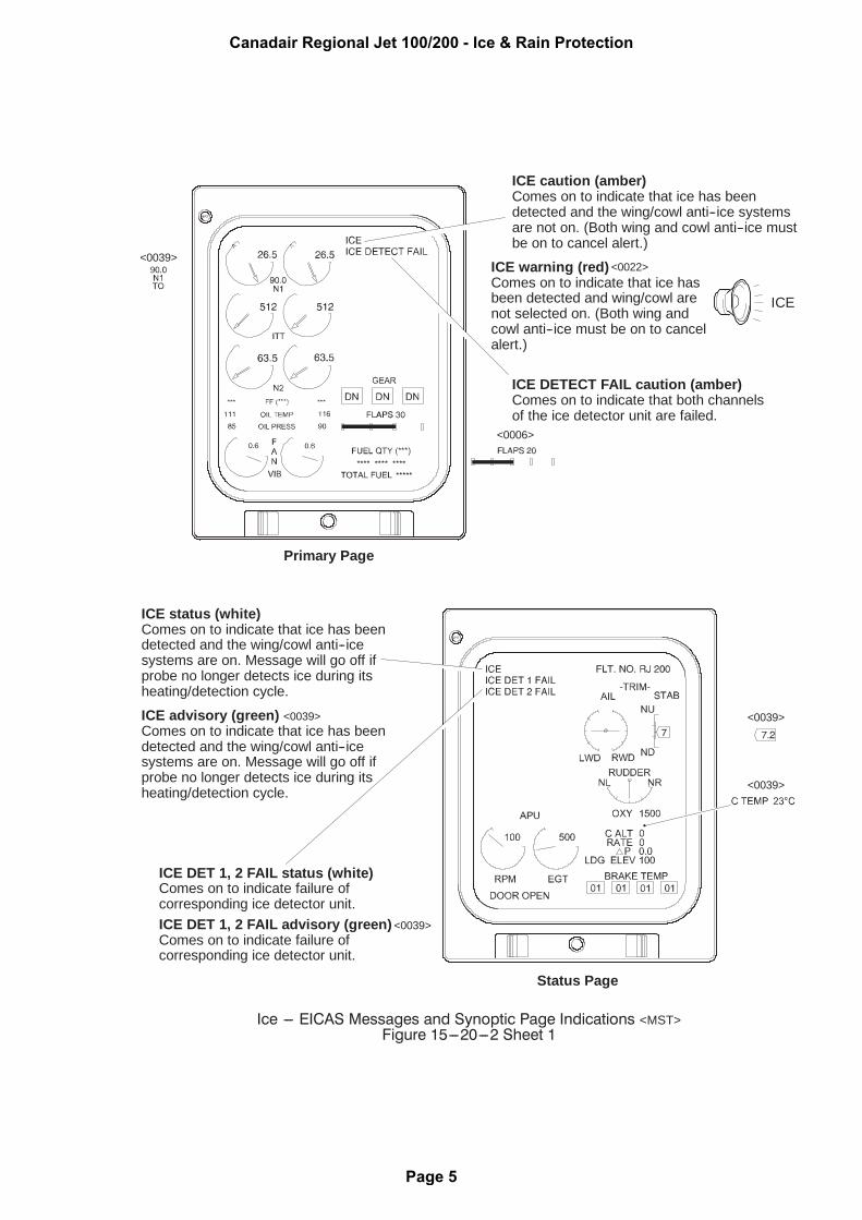
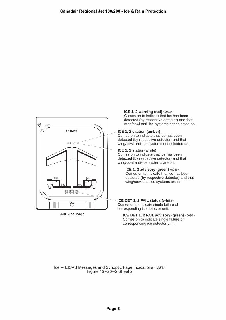
ICE warning (red)Comes on to indicate that ice hasbeen detected and wing/cowl arenot selected on. (Both wing andcowl anti--ice must be on to cancelalert.)
ICE status (white)Comes on to indicate that ice has beendetected and the wing/cowl anti--icesystems are on. Message will go off ifprobe no longer detects ice during itsheating/detection cycle.
Status Page
<0039>
<0039>
ICE caution (amber)Comes on to indicate that ice has beendetected and the wing/cowl anti--ice systemsare not on. (Both wing and cowl anti--ice mustbe on to cancel alert.)
ICE DETECT FAIL caution (amber)Comes on to indicate that both channelsof the ice detector unit are failed.
Primary Page
<0039>
ICE DET 1, 2 FAIL status (white)Comes on to indicate failure ofcorresponding ice detector unit.
<0006>
<0022>
ICE advisory (green)Comes on to indicate that ice has beendetected and the wing/cowl anti--icesystems are on. Message will go off ifprobe no longer detects ice during itsheating/detection cycle.
ICE DET 1, 2 FAIL advisory (green)Comes on to indicate failure ofcorresponding ice detector unit.
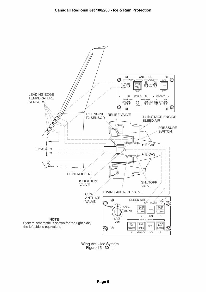
The wing anti-ice system prevents ice formation on the wing leading edges by heating thesurfaces with hot 14th stage engine bleed air. The hot bleed air is supplied throughinsulated ducting and released through piccolo tubes to the inner surface of the wing leadingedges. When normal anti--icing is selected, the wing leading edges are maintained at aconstant temperature to shed ice and to prevent further ice accumulation.
The wing anti-ice system is divided into identical left and right systems. In normal operation,each engine supplies hot bleed air to its respective wing anti-ice system. The systems areconnected by a, normally closed, 14 stage isolation valve. In the event one system fails, theisolation valve is opened to permit cross bleeding between systems. This ensures that winganti--icing is maintained to both systems.
The system is manually activated and is automatically controlled by an anti-ice temperaturecontroller located in the aft equipment compartment. The anti-ice temperature controllercontrols the wing anti-ice system by using inputs, received from temperature sensors locatedon each wing leading edge, to modulate the wing anti-ice valves to provide sufficient hot airto the leading edges to prevent ice formation.
14TH STAGE Isolation Valve Switch/LightWhen pressed in, bleed air isolation valveopens and OPEN (white) comes on.When pressed out, isolation valve closesand OPEN light goes out.
WING Anti--Ice SwitchControls operation of left and right wing (modulating and shutoff) valves.
14TH STAGE L/R Switch/LightsWhen pressed in, associated bleed air shutoff valve opens andCLOSED (white) goes out. When pressed out, valve closes andCLOSED (white) comes on.
DUCT FAIL (red) -- Comes on if sensors detect a failure inassociated duct section. DUCT FAIL goes out when the failedduct is isolated and temperature sensor cools.
Failure Switch/LightWing Overheat/Duct
Used to test bleed air leak detectionsystem and to indicate failures/overtemperature conditions.
OVHT (red) -- OVHT light comes onwhen overheat condition exists inwing leading edge.DUCT FAIL (red) -- Light comes onwhen bleed air leak is detected inwing left or right anti--ice ducts.Light goes out when the failed ductis isolated and temperature sensorcools.TEST -- When switch is pressed,the normal mode of the overheatsystem is tested. WING OVHTwarning message, ”Wing overheat”aural, OVHT light and WING A/ICEOK status message will come on.The position of the wing switch(either STBY, OFF or NORM) doesnot alter the test.
Wing Anti--Ice Flow Line(green)Comes on (with applicableEICAS advisory message)to indicate that winganti--ice system has beenselected on and isoperating normally.
Left Wing Anti--Icing Valve
Anti--Ice Page
Right 14th StageShutoff Valve
Right Wing Anti--IcingValve
14th Stage IsolationValve
OVHT warning (red)Comes on to indicateoverheat condition inrespective wing anti--icesystem.
WING A/ICE OK Message (green)Successful test of wing anti--ice system.
Left 14th Stage ShutoffValve
Valve Position IndicatorIndicates open
orIndicates invalid data
(no tube)
or
Indicates closed
or
WING A/ICE SNSRComes on to indicatewing anti--ice sensorfailure.
The engine cowl anti-ice system prevents ice formation on the engine intake leading edgesand the engine T2 sensors by heating the surfaces with hot 14th stage engine bleed air.The hot bleed air is supplied to the intake leading edges through respective L/R cowlanti--ice valves. (Refer to figure 1, section 30 of this chapter)
The left and right cowl anti-ice pressure regulating and shutoff valves are manuallycontrolled by the respective LH and RH COWL switches on the ANTI--ICE control panel.The valves are electrically controlled and pneumatically operated and are failed--safe to theopen position. When power is applied to the aircraft, the valves go to close. Crew activationof each system, opens the respective cowl anti-ice valve.
Each cowl anti-ice system also contains an overpressure relief valve mounted downstreamof the cowl anti-ice valves. When an overpressure condition occurs, the relief valve opens todump the excess pressure overboard and an indicator extends out the nose cowl to indicatethat the relief valve is open. After an overpressure, the relief valve remains open and theindicator is visable during a walkaround. Maintenance should be advised before resettingthe relief valve.
Valve status is displayed on the EICAS, ANTI--ICE synoptic page.
L, R COWL A/ICE caution (amber)Comes on to indicate failure of cowlanti--ice valve.If applicable cowl anti--ice valve isswitched on then the messageindicates insufficient pressure.If applicable cowl anti--ice valve isswitched off, the message indicatespressure is in the system (i.e., valvefailed open).
Anti--Ice Panel
<0006>
COWL Anti--Ice LH/RH SwitchesControls operation of cowl anti--iceshut--off valves.
ON -- Opens applicable cowlanti--ice shut--off valve, to provide14th stage bleed air to the cowland T2 probe at the engine inlet.OFF -- Closes applicable cowlanti--ice shutoff valve.
Green -- OperationalAmber -- Cowl anti--icefailure.
Left Cowl Anti--Ice Valve
Indicates open (white)
Indicates invalid data(half--intensity magenta)
CMD (cyan)Reflects the position of thevalve as selected on theanti--icepanel.
NOTEFailure of an anti--ice valve isindicated by valve outlineturning amber.
Wing Anti--Ice Flow Line(green)Comes on (with applicableEICAS advisory message)to indicate that wing anti--icesystem has been selectedon and is operating normally.
Cowl Anti--Ice Flow Line(green)Comes on (with applicableEICAS advisory message)to indicate that applicablecowl anti--ice system hasbeen selected on and isoperating normally.
Air data probes and sensors are located on the left and right sides of the forward fuselageand extend into the airstream. The air data probes and sensors are monitored andcontrolled by three independent and identical air data sensor heater controllers (ADSHC’s).Controller 1 monitors the heater elements for the left pitot, left and right base heaters, leftangle of attack (AOA) vane and left static port. Controller 2 monitors the right pitot, rightAOA vane, total air temperature (TAT) probe and right static port. Controller 3 monitors thestandby pitot probe. The ADSHC’s electronically control the heating elements to prevent iceformation that may cause erroneous air data information. The air data sensor heatingsystem is activated automatically on the ground and in flight.
The ground mode has two operational heating modes, automatic and manual When eitherengine generator is on and the LH and RH PROBES switches, on the ANTI--ICE controlpanel, are OFF, the LH and RH pitot probes and the standby pitot probe are heated at halfpower (The APU does not control this function). The static ports, base heaters, TAT probe,and the AOA vanes are not powered automatically in the ground mode. However, they canbe heated by selecting the LH and RH PROBES switches to ON.
NOTE
During ground operations, when AC power is on--lineand the air--bridge is being used, the probes will bepowered and the ground crew should be advised ofthe hazard areas.
In the flight mode, the automatic control function is completely independent of the controlswitches. The controllers automatically supply full power to all the air data probes andsensors, regardless of PROBES switch position.
NOTE
Following an ADG deployment, if the powerinterruption lasts longer than 5 seconds, the PITOTBASE HEAT caution message will remain latched.After landing, the heater ADS CONT 1 circuit breaker(CB4--A7) may be pulled and reset to remove thecaution message.
Effectivity:
� Airplanes 7003 to 7189 incorporating SB 601R--24--082 and aircraft 7190 and subsequent.
NOTE
After engine start,with the engine generators off, the L,R and STBY PITOT HEAT caution messages will remaindisplayed until an engine generator is brought on line.
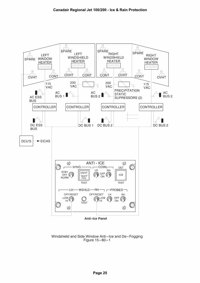
1. WINDSHIELD AND SIDE WINDOW ANTI--ICE AND DE--FOGGING SYSTEM
Anti-icing and defogging of the windshields and side windows is achieved by electricallyheating the windshields and side windows. Each windshield and side window incorporatesan electrical heating element and three temperature sensors. One sensor is used for normaltemperature control and another is used for overheat detection. The third sensor is a spare,and is used if one of the other sensors fail.
The amount of heat supplied to the windshields and side windows is controlled by fouridentical temperature controllers, one for each window. The controllers automaticallyregulate power to the heating elements as selected by the LOW/HI WSHLD switches on theANTI--ICE control panel. When the switches are set to HI, the windshields are heated at ahigh temperature, but the side window temperatures are maintained at the LOW setting.
When an overheat condition is detected, the associated controller removes the power to theheater element and posts a caution message on the EICAS primary page.
NOTE
If a windshield or side window heater fails, the relatedwindshield or side window may fog up during highhumidity conditions.
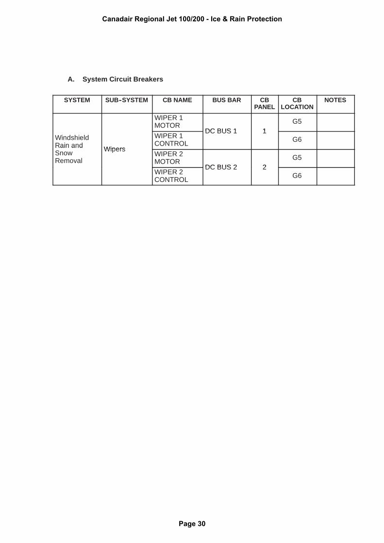
The windshield wiper system is designed to remove rain and/or snow from the pilot andco-pilot’s windshields.
The windshield wiper system consists of independent pilot and copilot systems. Eachsystem consists of a windshield wiper and motor. Each pilot has a selector, located on theWIPER control panel that actuates both wipers. Under normal operations, both wipers willoperate in the same mode when selected from either panel. If each selector is set to adifferent mode, the last selection made overrides the previous selection. If one wiper systemfails, the remaining system will still be functional.
With either switch selected to the SLOW position, the wipers operate at approximately 80cycles per minute. At FAST position the wipers operate at approximately 125 cycles perminute.