• To reduce lead-time in Product Development • To Produce Parts with Complex geometry • Freedom for Designer • Development of New Materials and Process NEED FOR ADDITIVE MANUFACTURING “A drawing is worth of 1000 Words A Prototype is worth of 1000 Drawings ”
Transcript
• To reduce lead-time in Product Development
• To Produce Parts with Complex geometry
• Freedom for Designer
• Development of New Materials and Process
NEED FOR ADDITIVE MANUFACTURING
“A drawing is worth of 1000 Words
A Prototype is worth of 1000 Drawings ”
Manufacturing Sequence
TOO LONG TIME FOR PRODUCT DEVELOPMENT
Additive Manufacturing
INTRODUCTION
The ASTM has defined ‘Additive Manufacturing' AM) as a (ASTM
International, 2012): "process of joining materials to make objects
from 3D model data, usually layer upon layer, as opposed to
subtractive manufacturing methodologies, such as traditional
machining.”
Fig 1. Bee-hive-An Analogy for AM
Additive Manufacturing (AM) - Principle
3D CAD Data-
(STL File)
Slicing
Building of part on RP M/c
Physical part
Fig 3. Principle of Additive Manufacturing
Four major aspects of Additive Manufacturing
Fig .The Rapid prototyping wheel depicting the four major aspects of AM(Source: Rapid Prototyping,Chua C.K, Leong K.E and Lim C.S)
Source : Wohlers Associates ,Inc
Time compression engineering
Fig . Time-Compression Engineering(Source: Rapid Manufacturing, D. T. Pham and S.S. Dimov)
History of Additive Manufacturing
Fig . A method for making moulds for topographical relief maps [Blanther,1892](Source: Rapid Manufacturing, D. T. Pham and S.S. Dimov)
The roots of AM can be traced to two technical areas:
1. Topography
2. Photo sculpture.
• A layered method was
proposed by Blanther (1892)
for making moulds for
topographical relief maps.
• Both positive and negative 3D
surfaces were to be
assembled from a series of
wax plates cut along the
topographical contour lines.
TOPOGRAPHY:
(Source: Rapid Manufacturing, D. T. Pham and S.S. Dimov)
History of Additive Manufacturing
Fig 6. The layer manufacturing system proposed by Munz [1956]
Photo sculpture
• This is a technique [Bogart, 1979]
proposed in the 19th century for
creating replicas of 3D objects.
• The technique involves
photographing the object
simultaneously with 24 cameras
equally spaced around a circular
room and then using the silhouette of
each photograph to carve 1/24th of a
cylindrical portion of the object.
Development work in the area of AM continued in the 1960s and 1970s and a
number of patents have been filed on different methods and systems. These
include:
• A method for fabricating objects from powdered materials by heating particles
locally and fusing them together employing a laser, electron beam, or plasma
beam [Ciraud, 1972].
• A process for producing plastic patterns by selective 3D polymerisation of a
photosensitive polymer at the intersection of two laser beams [Swainson,
1977].
• A photopolymer RP system for building objects in layers [Kodama, 1981]. A
mask is used to control the exposure of the UV source when producing a
cross section of the model.
• A system that directs a UV laser beam to a polymer layer by means of a
mirror system on an x-y plotter [Herbert, 1982].
History of Additive Manufacturing
Advantages of Additive Manufacturing
The benefits of RP systems can be categorized into direct and indirect benefits.
Direct benefits:
The ability to experiment with physical objects of any
complexity in are relatively short period of time.
(Source: Rapid Prototyping,Chua C.K, Leong K.E and Lim C.S)
Project time and product complexity in 25 years’ time frame
(Source: Rapid Prototyping,Chua C.K, Leong K.E and Lim C.S)
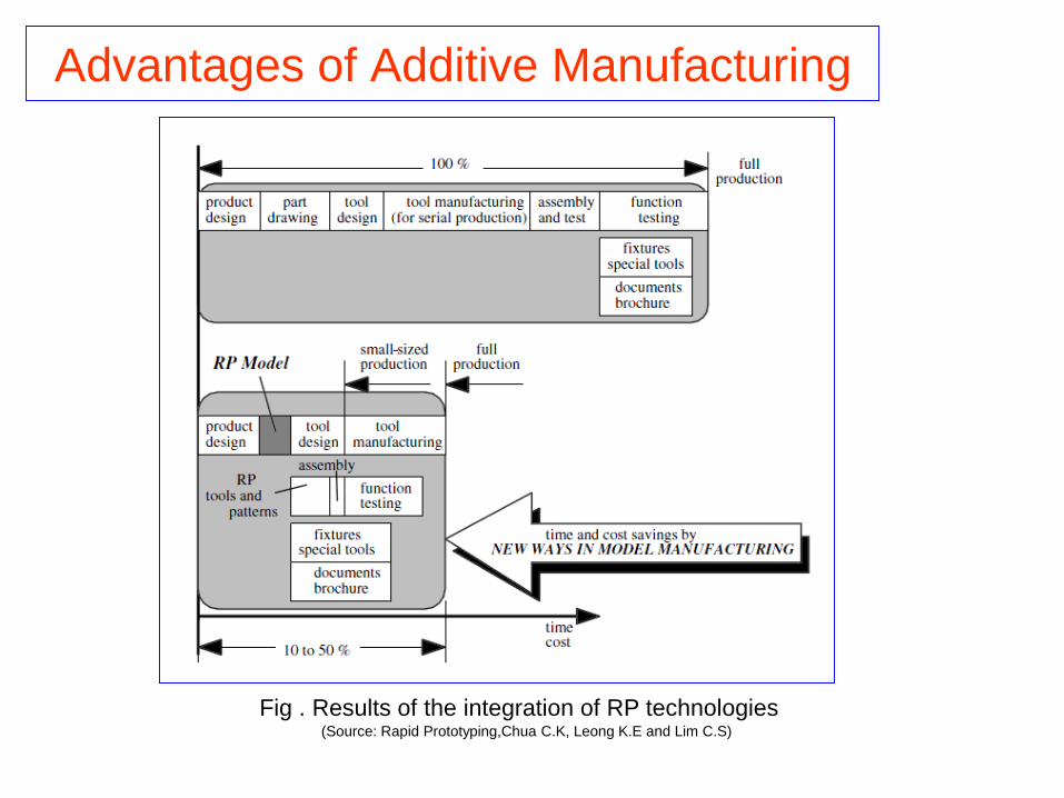
Advantages of Additive Manufacturing
Fig . Results of the integration of RP technologies
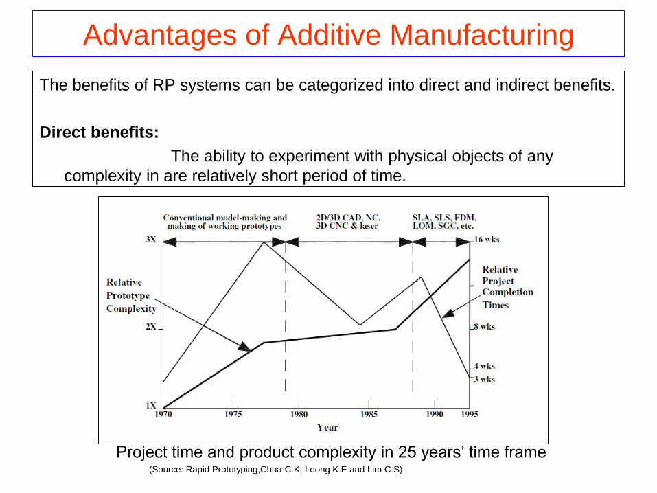
Advantages of Additive Manufacturing
The benefits of RP systems can be categorized into direct and indirect benefits.
Direct benefits:
The ability to experiment with physical objects of any
complexity in are relatively short period of time.
(Source: Rapid Prototyping,Chua C.K, Leong K.E and Lim C.S)
Project time and product complexity in 25 years’ time frame
Benefits to Product Designers
• The product designers can increase part complexity with little significant effects on lead time and cost.
• They can reduce parts count by combining features in single-piece parts that are previously made from several because of poor tool accessibility or the need to minimize machining and waste.
• With fewer parts, time spent on tolerance analysis, selecting fasteners, detailing screw holes and assembly drawings is greatly reduced.
• There will also be fewer constraints in the form of parts design without regard to draft angles, parting lines or other such constraints.
• Parts which cannot easily be set up for machining, or have accurate, large thin walls, or do not use stock shapes to minimize machining and waste can now be designed.
• They can minimize material and optimize strength/weight ratios without regard to the cost of machining.
• They can minimize time-consuming discussions and evaluations of manufacturing possibilities.
FREEDOM FOR DESIGNER
Design For Manufacture
Not Possible by
conventional processes
They can minimize material and optimize strength/weight ratios without
regard to the cost of machining.
Benefits to Product Designers
Fig: Load Bearing Hydraulic Manifold
Benefits to Product Designers
They can reduce parts count by combining features in single-piece parts that
are previously made from several because of poor tool accessibility or the need
to minimize machining and waste.
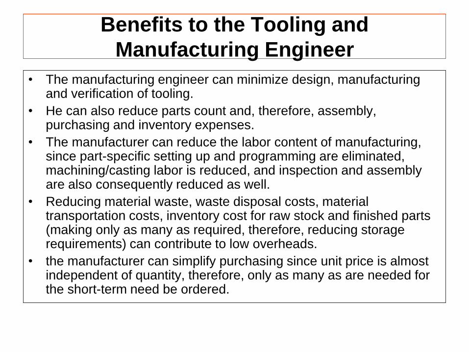
Benefits to the Tooling and
Manufacturing Engineer
• The manufacturing engineer can minimize design, manufacturing and verification of tooling.
• He can also reduce parts count and, therefore, assembly, purchasing and inventory expenses.
• The manufacturer can reduce the labor content of manufacturing, since part-specific setting up and programming are eliminated, machining/casting labor is reduced, and inspection and assembly are also consequently reduced as well.
• Reducing material waste, waste disposal costs, material transportation costs, inventory cost for raw stock and finished parts (making only as many as required, therefore, reducing storage requirements) can contribute to low overheads.
• the manufacturer can simplify purchasing since unit price is almost independent of quantity, therefore, only as many as are needed for the short-term need be ordered.
• One can purchase one general purpose machine rather than many special purpose machines and therefore, reduce capital equipment and maintenance expenses,
need fewer specialized operators and less training.• Furthermore, one can reduce the inspection reject rate
since the number of tight tolerances required when parts must mate can be reduced.
• One can avoid design misinterpretations (instead, “what you design is what you get”), quickly change design dimensions to deal with tighter tolerances and achieve higher part repeatability, since tool wear is eliminated.
• one can reduce spare parts inventories (produce spare on demand, even for obsolete products).
Benefits to the Tooling and
Manufacturing Engineer
Benefits to the Tooling and Manufacturing Engineer
Plastic part
Core & Cavity
Build-time : 5 Hours
The manufacturing engineer can minimize design, manufacturing and verification of
tooling.
Indirect Benefits
Benefits to Marketing
It can greatly reduce time-to-market, resulting in
• Reduced risk as there is no need to project customer needs and
market dynamics several years into the future.
• Products which fit customer needs much more closely.
• Products offering the price/performance of the latest technology
• New products being test-marketed economically.
• Marketing can also change production capacity according to market
demand, possibly in real time and with little impact on
manufacturing.
• One can increase the diversity of product offerings and pursue
market niches currently too small to justify due to tooling cost
(including custom and semi-custom production).
• One can easily expand distribution and
quickly enter foreign markets.
Benefits to the Consumer
•The consumer can buy products which meet more closely individual
needs and wants.
•Much wider diversity of offerings to choose from.
•Consumer can buy products at lower prices, since the manufacturers’
savings
will ultimately be passed on.
Indirect Benefits
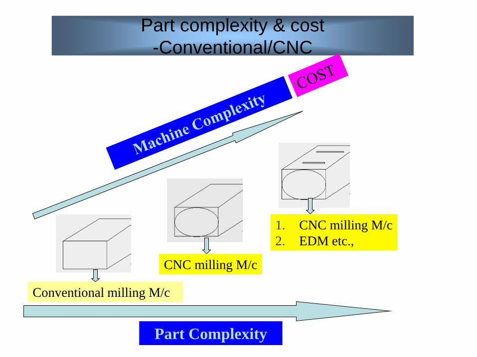
Part complexity & cost
-Conventional/CNC
Conventional milling M/c
CNC milling M/c
1. CNC milling M/c
2. EDM etc.,
Part Complexity
Part complexity & cost
-AM Technology
Complexity of part
Aerospace
• Turbine blades made by DMLS from EOS (a Germanmanufacturer of laser sintering/melting systems) havefound their way onto test rigs.
• It is believed that a variety of metal parts made byadditive manufacturing will initially make their way ontoflying aircraft in 2-3 years and will become common in 10years.
• The opportunity is not only for flight hardware, but alsofor jet-powered boats, land-based power generators, andother applications of gas turbine engines.
Reference: David L. Bourell, Ming C. Leu, David W. Rosen, Roadmap for Additive Manufacturing Identifying the Future
of Freeform Processing, The University of Texas at Austin, Laboratory for Freeform Fabrication, 2009.
Biomedical
• Many universities and research institutes are exploring ways in which AM can be applied to medical implant design and manufacturing, tissue engineering, and regenerative medicine.
• Two companies in Italy have used AM to manufacturemore than 10,000 metal hip implants, thousands ofwhich have been implanted into human beings.(Theaverage life span is increasing-Japan)
• Meanwhile, Walter Reed Army Medical Center hasproduced 37 cranial (Skull) implants using electronbeam melting, an AM process from Arcam of Sweden.
Reference: David L. Bourell, Ming C. Leu, David W. Rosen, Roadmap for Additive Manufacturing Identifying the Future
of Freeform Processing, The University of Texas at Austin, Laboratory for Freeform Fabrication, 2009.
Dentistry
• The market for the production of dental products using
AM is on the verge of explosive growth.
• Dental labs are using DMLS from EOS and other direct
metal AM processes for the production of copings for
crowns and bridges.
• EOS has reported that the dental business is currently its
fastest growing area of AM for production applications.
Reference: David L. Bourell, Ming C. Leu, David W. Rosen, Roadmap for Additive Manufacturing Identifying the Future
of Freeform Processing, The University of Texas at Austin, Laboratory for Freeform Fabrication, 2009.
Automotive
• High-end cars of small production are
candidates for using AM.
• Bentley and Rover have shown that it is
feasible and have used AM for small,
complex parts.
• Motorsports industry –Helmet, car parts
Reference: David L. Bourell, Ming C. Leu, David W. Rosen, Roadmap for Additive Manufacturing Identifying the Future
of Freeform Processing, The University of Texas at Austin, Laboratory for Freeform Fabrication, 2009.
Defence
• Many products for Defence are:– high value, complex, low volumes.
• Some are customised such as– Unmanned aerial vehicles (UAVs),
– Light-weight gear and armor for soldiers,
– Portable power units,
– Communication devices,
– Ground-based robots,
– Production of spare parts in remote locations,
– Mobile parts hospitals, and legacy parts for aircrafts.
• With AM improvements that are expected in 10-12 years, the militarywill likely become a major user of additive manufacturing.
Reference: David L. Bourell, Ming C. Leu, David W. Rosen, Roadmap for Additive Manufacturing Identifying the Future
of Freeform Processing, The University of Texas at Austin, Laboratory for Freeform Fabrication, 2009.
Electronics
• AM can produce 3D printed circuit boards that wrap
around the contours of the product.
• Complex geometric features with multiple intake and
exhaust passages in a compact space for electrical
power generators can be fabricated using AM
• The potential to use various materials is also attractive
because some parts of these reactors/generators should
be made of low conductivity materials (e.g., plastics)
whereas other parts require high conductivity and/or
catalytic properties (e.g., metals).
Reference: David L. Bourell, Ming C. Leu, David W. Rosen, Roadmap for Additive Manufacturing Identifying the Future
of Freeform Processing, The University of Texas at Austin, Laboratory for Freeform Fabrication, 2009.
Jewelry
• In the future, jewelers will use AM to manufacture custom andlimited edition products.
• Lionel Dean of Future Factories is currently manufacturingimpressive pendants in titanium alloys.
• Lena Thorsson, formerly of Particular AB, showed that it is possibleto laser sinter gold alloys to produce beautiful chains andnecklaces that normally require complex and expensive machinery.
Reference: David L. Bourell, Ming C. Leu, David W. Rosen, Roadmap for Additive Manufacturing Identifying the Future
of Freeform Processing, The University of Texas at Austin, Laboratory for Freeform Fabrication, 2009.
Food
• Specialty food is said to be a $13 billion industry.
• With AM systems such as the open source Fab@Home machinefrom Cornell University, it is possible to make chocolates and cakeicing that include 3D figures, company logos, names, and otherobjects.
• It is also possible to consider the use of AM system to manufacturefood products in cheese, peanut butter etc that can be extrudedthrough a syringe.
Reference: David L. Bourell, Ming C. Leu, David W. Rosen, Roadmap for Additive Manufacturing Identifying the Future
of Freeform Processing, The University of Texas at Austin, Laboratory for Freeform Fabrication, 2009.
Education
• In 10-12 years, it is anticipated that schools will offer courses andprograms that include instruction on how to design for themanufacture of parts using AM.
• Innovative organizations will develop methods of product design thattake advantage of AM processes and materials.
Reference: David L. Bourell, Ming C. Leu, David W. Rosen, Roadmap for Additive Manufacturing Identifying the Future
of Freeform Processing, The University of Texas at Austin, Laboratory for Freeform Fabrication, 2009.
• Material
• Speed
• Complexity
• Accuracy
• Geometry
• Programming
Distinction Between AM and CNC Machining
Following are range of topics where comparisons between CNC machining and
AM can be made.
Distinction Between AM and CNC Machining
Material
AM CNC Machining
AM technology was
originally developed around
polymeric materials, waxes
and paper laminates.
Subsequently, there has
been introduction of
composites, metals,
and ceramics.
CNC machining to make
final products, it works
particularly well for hard,
relatively brittle materials
like steels and other metal
alloys to produce high
accuracy parts with well
defined properties.
AM parts may have voids or
anisotropy that are a
function of part orientation,
process parameters or how
the design was input to the
machine.
CNC parts will normally be
more homogeneous and
predictable in quality.
SPEED
AM CNC Machining
Shorter Lead time:
Irrespective of part complexity,
manufactured in single stage
Longer Lead time:
Multistage manufacturing process,
requiring repositioning or relocation of
parts within one machine or use of
more than one machine.
Setup and process planning time
remains same irrespective of part
complexity
Setup and process planning time,
increases particularly as parts become
more complex in their geometry.
Multiple parts are often batched
together inside a single AM build
which reduces setup lead time.
M/c and part set up is to be done
repetitively for each and every
component.
COMPLEXITY
AM CNC
Irrespective of part complexity, parts are
produced in single setup and in the AM
machine
M/c Setup and No of machines to produce
a component depends on part complexity.
AM processes are not constrained in
the same way and undercuts and
internal features can be easily built
without specific process planning.
Since a machining tool must be
carried in a spindle, there may be
certain accessibility constraints or
clashes preventing the tool from being
located on the machining surface of a
part.
Possible to build parts in single setup Certain parts cannot be fabricated by
CNC unless they are broken up into
components and reassembled at a
later stage.
Ex: a ship inside a bottle.
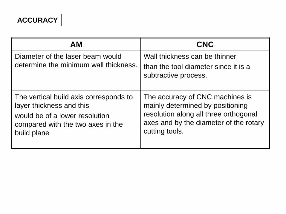
ACCURACY
AM CNC
Diameter of the laser beam would
determine the minimum wall thickness.
Wall thickness can be thinner
than the tool diameter since it is a
subtractive process.
The vertical build axis corresponds to
layer thickness and this
would be of a lower resolution
compared with the two axes in the
build plane
The accuracy of CNC machines is
mainly determined by positioning
resolution along all three orthogonal
axes and by the diameter of the rotary
cutting tools.
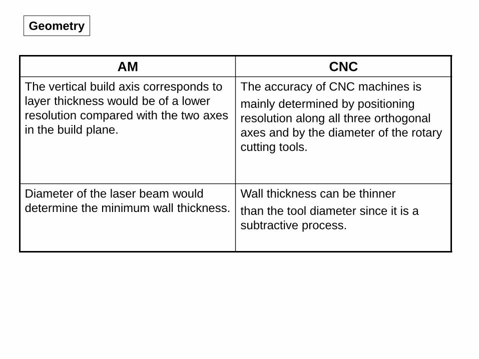
Geometry
AM CNC
The vertical build axis corresponds to
layer thickness would be of a lower
resolution compared with the two axes
in the build plane.
The accuracy of CNC machines is
mainly determined by positioning
resolution along all three orthogonal
axes and by the diameter of the rotary
cutting tools.
Diameter of the laser beam would
determine the minimum wall thickness.
Wall thickness can be thinner
than the tool diameter since it is a
subtractive process.
Programming
AM CNC
AM machines have options that must
be selected, but the range, complexity
and implications surrounding their
choice are minimal in comparison.
Program sequence for a CNC
machine is more which includes tool
selection, machine speed settings,
approach position, and angle, etc.
The worst that is likely to happen in
most AM machines is that the part will
not be built very well if the
programming is not done properly.
Incorrect programming of a
CNC machine could result in severe
damage to the machine and may even
be a safety risk.
Preliminary Summarized Comparison
Area of Comparison AM technology CNC
Materials Limited Nearly Unlimited
Maximum part size Varies Large enough to handle aerospace