Introduction to Aspect Signaling with JMRI/PanelPro Clinics in this series: Introduction to Aspect Signaling with JMRI/PanelPro 4:00 PM, Wednesday, July 6 th Aspect Based Signaling Internals with JMRI/PanelPro 4:00 PM, Thursday, July 7 th Clinics in this series: Introduction to Aspect Signaling with JMRI/PanelPro 4:00 PM, Wednesday, July 6 th Aspect Based Signaling Internals with JMRI/PanelPro 4:00 PM, Thursday, July 7 th Dick Bronson - RR-CirKits, Inc.
Transcript
Introduction to Aspect Signaling with JMRI/PanelPro
Clinics in this series:
Introduction to Aspect Signaling with JMRI/PanelPro4:00 PM, Wednesday, July 6th
Aspect Based Signaling Internals with JMRI/PanelPro
4:00 PM, Thursday, July 7th
Clinics in this series:
Introduction to Aspect Signaling with JMRI/PanelPro4:00 PM, Wednesday, July 6th
Aspect Based Signaling Internals with JMRI/PanelPro
4:00 PM, Thursday, July 7th
Dick Bronson - RRCirKits, Inc.
Resources
Web Sites http://www.rrsignalpix.com/index.html A site for Signals and rules.
By Zachary Gillihan
http://www.ctcparts.com/ An excellent site for CTC information.By Michael Burgett
http://www.RR-CirKits.com/ Our web site for signal control hardware.By Dick Bronson
✔ Signal System typesThere are two general methods of signaling in use for
railroads. The first is 'Route' based, and the second is 'Speed' based.
✔ Route based signals:Route based signals give a general indication of the
route condition ahead of the train.
✔ Speed based signals:Speed based signals primarily give the target speed for
the track ahead of the train.
Signal System Types
Getting Started
✔ Route based signals:Route based signals in the USA give a general
indication of the route condition ahead of the train. Some european route systems may give very specific information. Typically the western US railroads used route based signals. The long distances between signals leaves plenty of room for stopping in advance of signals with only one or two signals of advanced warning.
JMRI has supported Route Based signaling with SSL (Simple Signal Logic) for a number of years now. Some small amount of speed information may be combined with the route information by the use of flashing aspects.
Signal System Types
UP Route signal near Barstow, CA
Photo by Chris Sanfino
Signal System Types
Getting Started
Speed based signals:Speed based signals in the USA are usually found on
the more congested eastern routes where the added cost of shorter blocks and more complex signal hardware is justified by the denser east coast traffic patterns.
Speed signaling requires many different aspects in order to indicate each combination of speeds that apply to the next section of track.
Support for speed signaling is just now being added into JMRI and is called ”Aspect Signaling”. This new capability is the topic of todays clinic.
Signal System Types
Speed signal in Sauget, IL
Signal System Types
Getting Started
✔ Setting the PanelPro PreferencesSetup your hardware according to the information found in the
JMRI Help pages. Select 'Help' – 'General Help...' then navigate down to 'DecoderPro' – 'DecoderPro Manual' – 'Getting Started' – 'Setting Preferences'. On the web go to: http://www.jmri.org/help/en/manual/Getting_Started.shtml#Start
✔ Note:The setup options for PanelPro are saved in their own startup
file, distinct from those in DecoderPro. Normally you will use the same settings for both DecoderPro and PanelPro.
Be sure to not try and run both PanelPro and DecoderPro at the same time. They are essentially the same program, so you have the full capabilities of each no matter how you initially start it running.
Use your own operating systems method for starting the program. In this demo we are running with Ubuntu Linux.
Starting the Program
Getting Started
Use your own operating systems method for starting the program. In this demo we are running with Ubuntu Linux.
Select the desired startup icon and single click.
Starting the Program
Getting Started
The initial PanelPro window includes information about the version numbers of JMRI, Java, and also information about the computer interface. Include this information as well as your computer's operating system type in any support requests.
Useful Information
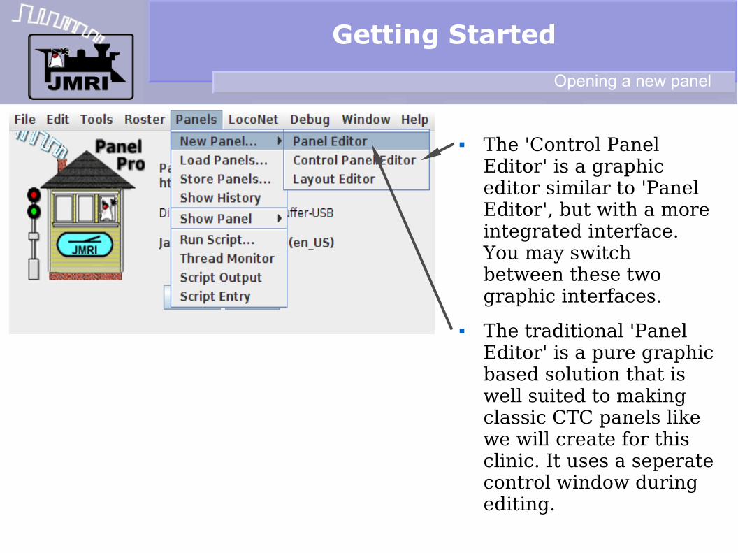
To get started on building a panel open the 'Panels' drop down list and select 'New Panel'
This will open a selection between the 'Layout Editor' and 'Panel Editor'
The 'Layout Editor' is a vector based way to create a drawing that follows your layout plan and which auto captures much of the information required for Signaling.
Getting Started
Opening a new panel
The 'Control Panel Editor' is a graphic editor similar to 'Panel Editor', but with a more integrated interface. You may switch between these two graphic interfaces.
The traditional 'Panel Editor' is a pure graphic based solution that is well suited to making classic CTC panels like we will create for this clinic. It uses a seperate control window during editing.
Getting Started
Opening a new panel
Simple Signal Logic
We will start out with a panel representing the demo layout, but with simple signals.
Opening a demo panel
Simple Signal Logic
We will start out with a panel representing the demo layout, but with simple signals.
The relationships between the signals and the layout are simple. (Simple Signal Logic)
Block Occupied = Stop
Turnout not aligned = Stop
Next signal Stop = Approach
Next signal Approach = Flash
None of the above = Clear
ABS Relationships
Simple Signal Logic
We will start out with a panel representing the demo layout, but with simple signals.
The relationships between the signals and the layout are simple. (Simple Signal Logic)
Block Occupied = Stop
Turnout not aligned = Stop
Next signal Stop = Approach
Next signal Approach = Flash
None of the above = Clear
There are a few added options for linking in CTC panels but basicly this is the extent of the complexity.
CTC Overlay
Simple Signal Logic
We will start out with a panel representing the demo layout, but with simple signals.
The relationships between the signals and the layout are simple. (Simple Signal Logic)
Block Occupied = Stop
Turnout not aligned = Stop
Next signal Stop = Approach
Next signal Approach = Flash
None of the above = Clear
There are a few added options for linking in CTC panels but basicly this is the extent of the complexity.
This is ABS Route Signaling.
ABS (Automatic Block Signals)
Simple Signal Logic
This is ABS Route Signaling.
ABS (Automatic Block Signals)
Simple Signal Logic
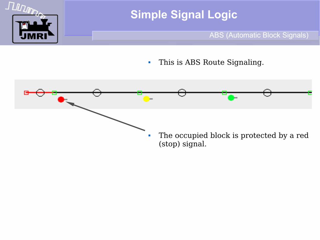
This is ABS Route Signaling.
The occupied block is protected by a red (stop) signal.
ABS (Automatic Block Signals)
Simple Signal Logic
This is ABS Route Signaling.
The occupied block is protected by a red (stop) signal.
The stop signal is protected by a yellow (approach) signal. I.e. You are ”approaching” a stop signal.
ABS (Automatic Block Signals)
Simple Signal Logic
This is ABS Route Signaling.
The occupied block is protected by a red (stop) signal.
The stop signal is protected by a yellow (approach) signal. I.e. You are ”approaching” a stop signal.
The approach signal may optionally be protected by a flashing yellow 'Advance Approach' signal. If not one of the previous, then Clear.
ABS (Automatic Block Signals)
Speed Based Signals
Speed Based Signals Speed Signaling gives the engineer information regarding how fast his train
must travel in the upcoming segment of track. In general there are two speed zones in a signal block.
The first zone is that portion of a block when any part of the train is in an interlocking section. For example, as defined in the CSX rules; ”through turnouts, crossovers, sidings, and over power routed switches.”
The second speed zone is the speed allowed for the duration of the block.
The ”Name” of the signal aspect reflects these two different pieces of speed information. For example ”Medium Clear” indicates; 'Medium speed through turnouts, crossovers, sidings, and over power routed switches; then proceed. ”Medium Approach” indicates; 'Medium speed through turnouts, crossovers, sidings, and over power routed switches; then proceed, prepared to stop at next signal.
Zones
Speed Based Signals
The Speed based signal rules may sometimes be a bit more complex.
Speed Signal Rules
Speed Based Signals
The Speed based signal rules may sometimes be a bit more complex.
Speed Signal Rules
Speed Based Signals
The Speed based signal rules may sometimes be a bit more complex.
In this CSX example, a ”Stop” aspect may be 'protected' by any of three different aspects. Approach, Medium Approach, or Slow Approach.
Speed Signal Rules
Speed Based Signals
The Speed based signal rules may sometimes be a bit more complex.
In this CSX example, a ”Stop” aspect may be 'protected' by any of three different aspects. Approach, Medium Approach, or Slow Approach.
This is the reason that JMRI now supports aspect based signaling.
Speed Signal Rules
Using Panel Editor
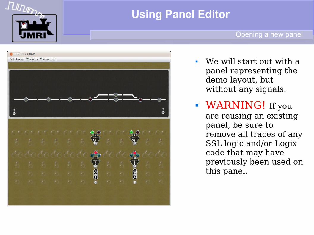
We will start out with a panel representing the demo layout, but without any signals.
Opening a new panel
Using Panel Editor
We will start out with a panel representing the demo layout, but without any signals.
WARNING! If you are reusing an existing panel, be sure to remove all traces of any SSL logic and/or Logix code that may have previously been used on this panel.
Opening a new panel
Using Panel Editor
Using your favorite text editor, NOT a word processor, search for ”<signalelement ” and remove each entry and all of its included data. (Example highlighted in red) Other instances to remove shown in green.
Manual Edit
Using Panel Editor
We will start out with a panel representing the demo layout, but without any signals.
WARNING! If you are reusing an existing panel, be sure to remove all traces of any SSL logic and/or Logix code that may have previously been used on this panel.
Once you have a panel with your required detection and turnouts you can add your signal masts.
Opening a new panel
Using Panel Editor
I have spaced out the track images and lever spacing to allow the fitting of the signal masts onto this demo panel. Normally a CTC panel does not include any actual signal information, but for our purposes it makes things easier to understand.
Opening a new panel
Using Panel Editor
I have spaced out the track images and lever spacing to allow the fitting of the signal masts onto this demo panel. Normally a CTC panel does not include any actual signal information, but for our purposes it makes things easier to understand.
I have only included the turnout and signal direction levers for these two interlocking points.
Opening a new panel
Using Panel Editor
I have spaced out the track images and lever spacing to allow the fitting of the signal masts onto this demo panel. Normally a CTC panel does not include any actual signal information, but for our purposes it makes things easier to understand.
I have included the turnout and signal direction levers for two interlocking points.
I have also included a pair of ”Call On” switches and indicators to enable ”restricting” moves using Logix.
Opening a new panel
Using Panel Editor
These two levers are used to simulate off panel traffic information. 'Toward the center' is traffic ”onto the panel”, 'center' is ”occupied” and 'away from center' is traffic ”off of the panel”.
Opening a new panel
Adding Signal Heads
The current version of JMRI 2.12 only has the capability to create masts from individual signal heads. This may be because there are not any currently available products that understand ”aspect” commands. We expect this to change in the near future.
Due to these present limitations you must first build a signal head table using the hardware that you have available. The following table is for our demo hardware configured as if it were a Digitrax SE8c signal driver. In fact it is our prototype RR-CirKits LNCP unit that does understand aspects. (but see above limitations)
Signal Head table
Adding Signal Masts
The new signal mast (aspect based) signaling capability in JMRI uses the signal types themselves to determine the necessary rules of operation. This greatly simplifies the implementation of any signal system, but especially one that is more complex than the ABS signals currently supported by SSL. The intent is that, like Decoder definitions are currently added to DecoderPro, signal definitions will be added for each prototype RR rule book.
Signal Mast basics
Adding Signal Masts
The rules that we are using are taken from the CSX-1998 Signal Rules – 281-298.
Signal Mast basics CSX Rules
Adding Signal Masts
The rules that we are using are taken from the CSX-1998 Signal Rules – 281-298.
Especially note that each mast configuration can only indicate some, but not all of the possible rules.
Signal Mast basics CSX Rules
Adding Signal Masts
The rules that we are using are taken from the CSX-1998 Signal Rules – 281-298.
Especially note that each mast configuration can only indicate some, but not all of the possible rules.
Specificly lets use the example of a single head dwarf signal. It can only show three rules; Slow Clear, Slow Approach, and Stop.
Using Aspect Signaling; on your model you would simply select the single head dwarf and JMRI will automatically choose the correct aspects to use.
Signal Mast basics CSX Rules
Adding Signal Masts
If your turnout number allowed for Medium Clear and Medium Approach speeds, then you would simply use a double head dwarf with a red upper marker or a high mast with red upper marker. JMRI will then adjust to these new available aspects in creating its rules.
The real beauty of all this is that each rule includes the speed information, both through the interlocking, and once the train has cleared the interlocking. The JMRI automated throttles will obey these different speeds as determined by the aspects shown.
Signal Mast basics CSX Rules
Using Panel Editor
Lets place our first mast at the first block boundry for east (right) bound traffic.
Opening a new panel
Using Panel Editor
Lets place our first mast at the first block boundry for east (right) bound traffic.
Open the 'Tools' and select 'Tables' – 'Signals' - 'Signal Masts'.
Opening a new panel
Using Panel Editor
Adding a mast
Lets place our first mast at the first block boundry for east (right) bound traffic.
Open the 'Tools' and select 'Tables' – 'Signals' - 'Signal Masts'.
This opens the Signal Masts window. Click on ”Add...” to create our first mast.
Using Panel Editor
Adding a mast
Lets place our first mast at the first block boundry for east (right) bound traffic.
Open the 'Tools' and select 'Tables' – 'Signals' - 'Signal Masts'.
This opens the Signal Masts window. Click on ”Add...” to create our first mast.
We will name the mast 2R and select the Signal System 'CSX-1998'. Note: as of the 2.12 release many signal systems are incomplete. Be sure to download the latest version to obtain the most complete rules available.
Using Panel Editor
Adding a mast
After selecting the desired signal system you need to select the specific mast used at this location. We will use the simple three color light high signal mast. Your options are limited by the types of mast arrangements used by your prototype. Be sure to select the mast type that can display the required aspects for this location.
Once you select the type of mast you will need to enter the ID of the head/s that make up the mast. (top to bottom) In this case it only requires one head, LH31, which is already located in our signal head table.
Using Panel Editor
Adding a mast
Clicking on OK adds the mast to the table.
Using Panel Editor
Adding a mast
Clicking on OK adds the mast to the table.
Add a comment.
Using Panel Editor
Adding a mast
Clicking on OK adds the mast to the table.
Add a comment.
Note that the mast already knows all of the possible indications that it can display. I have not located the error that causes two 'Stop' entries to appear.
Using Panel Editor
Adding a mast
Continue to add your masts noting that some masts will require two or even three heads to configure properly.
Using Panel Editor
Adding masts to a panel
Continue to add your masts noting that some masts will require two or even three heads to configure properly.
Once the mast table is built we can add the actual masts to our panel. Remember this part is not prototypical, but rather an aid to understanding and configuration.
From the Panel Editor window select Add Icon – Signal Mast.
Select the '2R' mast from those that we added.
Using Panel Editor
Adding masts to a panel
The mast will appear in the usual place.
Using Panel Editor
Adding masts to a panel
The mast will appear in the usual place.
Move it into position.
Using Panel Editor
Adding masts to a panel
The mast will appear in the usual place.
Move it into position.
Then rotate it into position. (90 degrees)
Using Panel Editor
Adding masts to a panel
The mast will appear in the usual place.
Move it into position.
Then rotate it into position. (90 degrees)
Again remember that the classic CTC panels did not have any indications showing any of the actual signal aspects. They did often include small signal images indicating the location of interlocking signals.
Using Panel Editor
Adding masts to a panel
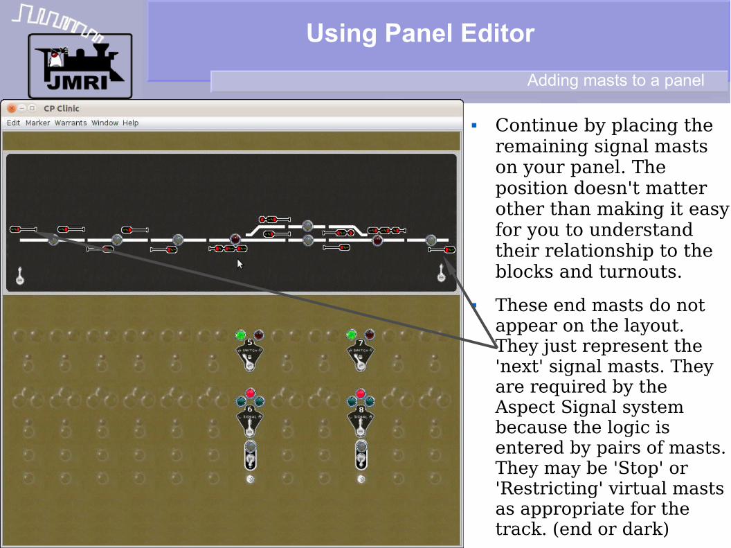
Continue by placing the remaining signal masts on your panel. The position doesn't matter other than making it easy for you to understand their relationship to the blocks and turnouts.
Using Panel Editor
Adding masts to a panel
Continue by placing the remaining signal masts on your panel. The position doesn't matter other than making it easy for you to understand their relationship to the blocks and turnouts.
These end masts do not appear on the layout. They just represent the 'next' signal masts. They are required by the Aspect Signal system because the logic is entered by pairs of masts. They may be 'Stop' or 'Restricting' virtual masts as appropriate for the track. (end or dark)
Using Panel Editor
Adding logic to your masts
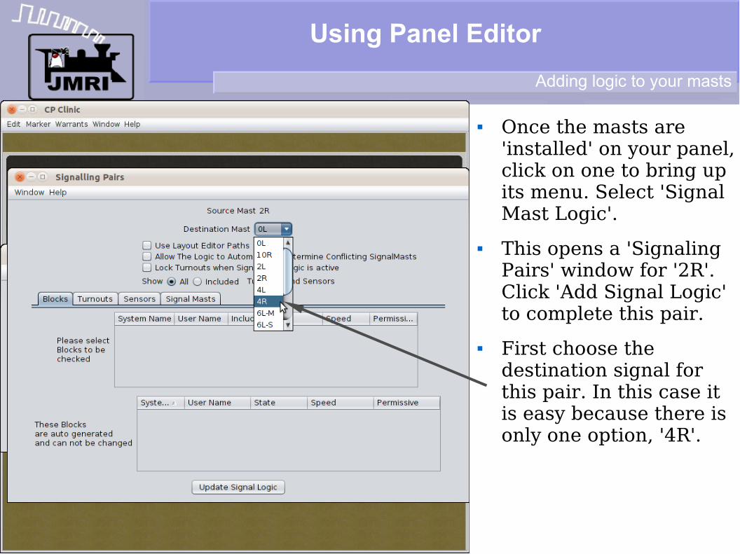
Once the masts are 'installed' on your panel, click on one to bring up its menu. Select 'Signal Mast Logic'.
Using Panel Editor
Adding logic to your masts
Once the masts are 'installed' on your panel, click on one to bring up its menu. Select 'Signal Mast Logic'.
This opens a 'Signaling Pairs' window for '2R'. Click 'Add Signal Logic' to complete this pair.
Using Panel Editor
Adding logic to your masts
Once the masts are 'installed' on your panel, click on one to bring up its menu. Select 'Signal Mast Logic'.
This opens a 'Signaling Pairs' window for '2R'. Click 'Add Signal Logic' to complete this pair.
First choose the destination signal for this pair. In this case it is easy because there is only one option, '4R'.
Now select the 'Sensors' tab and place a check by 'IS9:TK' which is the BOD for this block.
Using Panel Editor
Adding logic to your masts
We have not defined any 'Blocks', and there are no turnouts nor crossing tracks with extra masts to watch, so we are finished. Click on 'Update Signal Logic'.
Using Panel Editor
Adding logic to your masts
We have not defined any 'Blocks', and there are no turnouts nor crossing tracks with extra masts to watch, so we are finished. Click on 'Update Signal Logic'.
Actually for this demo I have added two other sensors to watch. The first is 'IS0:RDGL' (Internal Sensor 0: Right Direction siGnal Lever). The other is 'IS6:LDGK' (Internal Sensor 6: Left Direction siGnal indicaKator). These let me interact with the mast from the panel.
Using Panel Editor
Adding logic to your masts
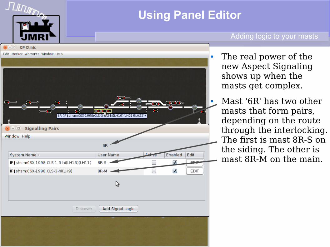
The real power of the new Aspect Signaling shows up when the masts get complex.
Using Panel Editor
Adding logic to your masts
The real power of the new Aspect Signaling shows up when the masts get complex.
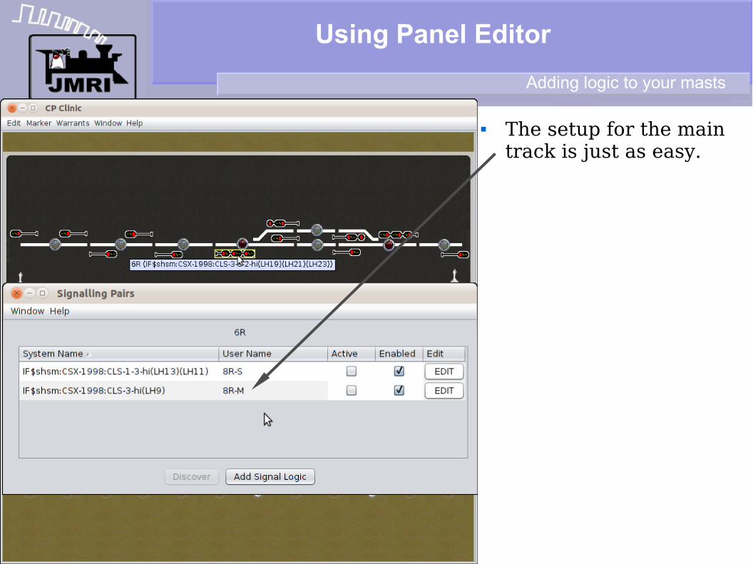
Mast '6R' has two other masts that form pairs, depending on the route through the interlocking. The first is mast 8R-S on the siding. The other is mast 8R-M on the main.
Using Panel Editor
Adding logic to your masts
The real power of the new Aspect Signaling shows up when the masts get complex.
Mast '6R' has two other masts that form pairs, depending on the route through the interlocking. The first is mast 8R-S on the siding. The other is mast 8R-M on the main.
Looking at the siding pair we have added the 'Turnouts' LT5 Thrown.
For 'Sensors' we look at the OS, the Siding, and the direction of traffic.
Using Panel Editor
Adding logic to your masts
The setup for the main track is just as easy.
Using Panel Editor
Rules
The setup for the main track is just as easy.
All the 'rules' are built into the JMRI signal mast tables, and automatically applied as required by your specific railroad's rule book. No more need to support the dead tree and ink industries to purchase thick signal manuals plus years of study in engineering and computer science just to understand how to write your Logix.
Recap
1) Setup your track diagram in the Panel Editor or Layout Editor.
Steps
Recap
1) Setup your track diagram in the Panel Editor or Layout Editor.
2) Identify the type of signaling system you're trying to create - speed based, route based or a bit of both?
Steps
Recap
1) Setup your track diagram in the Panel Editor or Layout Editor.
2) Identify the type of signaling system you're trying to create - speed based, route based or a bit of both?
3) Choose one of the available appearance and aspects.xml files for your system, or create one. (see next clinic in this series)
4) Setup all of your signal heads in the Signal Head table.
5) Setup your masts in the Signal Mast table.
6) Place the masts onto your panel.
7) Create the signal pairings so the logic will propagate from mast to mast.
Steps
Aspect Signaling
What we have covered so far: Getting started – Panel Editor Adding a background image Adding heads Adding masts Adding mast logic
Wrap up
Aspect Signaling
What we have covered so far: Getting started – Panel Editor Adding a background image Adding heads Adding masts Adding mast logic
Where we are going: Building your own signal sets and their rules Using layout Editor to automate the adding of masts