56
Introduction to Digital Communications Aaron Gulliver Dept. of Electrical and Computer Engineering University of Victoria
Introduction to Digital Communications
Aaron Gulliver
Dept. of Electrical and Computer Engineering
University of Victoria
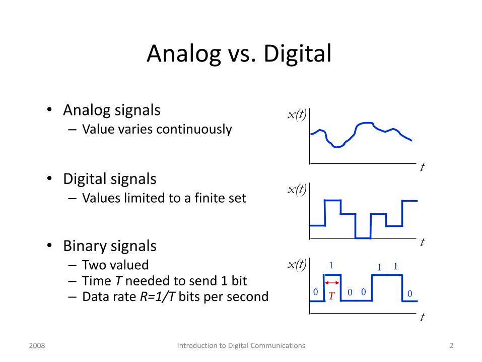
Analog vs. Digital
• Analog signals– Value varies continuously
• Digital signals– Values limited to a finite set
• Binary signals– Two valued– Time T needed to send 1 bit– Data rate R=1/T bits per second
t
x(t)
t
x(t)
t
x(t) 1
0 0 0
1 1
0T
2Introduction to Digital Communications2008
Information Representation
• Communication systems must convert information into a form suitable for transmission
• Analog systemsAnalog signals are directly modulated
– AM, FM radio
• Digital systems Generate bits and transmit digital signals
– Computer communications, Cellular telephones
• Analog signals can be converted into digital signals
3Introduction to Digital Communications2008
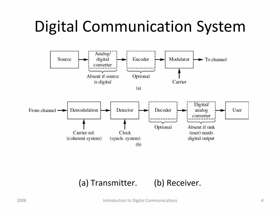
Digital Communication System
(a) Transmitter. (b) Receiver.
4Introduction to Digital Communications2008

Digital Transmitter• Matches the message to the channel• If the message is analog, it must be sampled in time and
quantized in amplitude. – discrete signal in time and amplitude
• Encoder: – adds redundancy for error correction.
• Modulation encodes the message into the amplitude, phase or frequency of the carrier signal (PSK, FSK, QAM, OFDM, PAM, PPM)
• Advantages: – Reduces noise and interference– Multiplexing– Channel assignment
• Examples: television, radio, 802.11, cellphones, bluetooth, GPS, …
52008 Introduction to Digital Communications
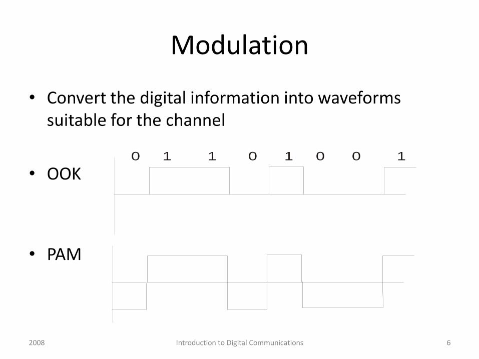
Modulation
• Convert the digital information into waveforms suitable for the channel
• OOK
• PAM
0 1 1 0 1 0 0 1
6Introduction to Digital Communications2008
Receiver
7
• Extracts the message from the received signal
• Operations: Filtering, Amplification, Demodulation
• The ideal receiver output is a scaled, delayed version of the message signal
• Decoder:
• estimates the original message from the received signal.
2008 Introduction to Digital Communications
Channel
8
• Physical medium that that the signal is transmitted through
• Examples: Air, wires, coaxial cables, fiber optic cables
• Every channel introduces some amount of distortion, noise and interference
• The channel properties determine
• Data throughput of the system
• Quality of service (QoS) offered by the system
2008 Introduction to Digital Communications

Noise and Interference
9
• Internal Noise
– Generated by components within a communication system (thermal noise)
• External Noise and Interference
– Atmospheric noise (electrical discharges)
– Man-made noise (ignition noise)
– Multipath interference (multiple transmission paths)
– Multiple access interference (signals from other users)
2008 Introduction to Digital Communications
Advantages
• Many sources are digital in nature– Data, images, text, video, music
• Different sources can be treated the same• Flexibility
– Encryption– Compression (source coding)– Error correction/detection
• Reliable reproduction of signals - regeneration– Two states vs. infinite variety of shapes
• Greater immunity to noise and interference• Power efficient and spectral efficient
10Introduction to Digital Communications2008
Introduction to Digital Communications 11
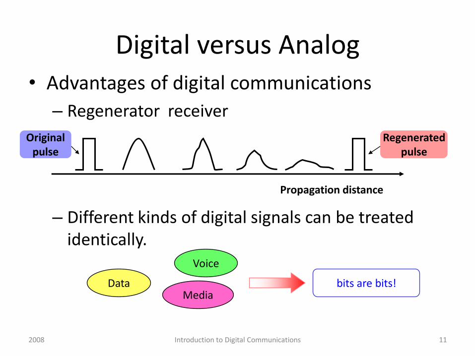
Digital versus Analog• Advantages of digital communications
– Regenerator receiver
– Different kinds of digital signals can be treated identically.
Data
Voice
Media
Propagation distance
Originalpulse
Regeneratedpulse
bits are bits!
2008

Digital Advantages
• Source coding compression algorithms can dramatically reduce the bit rate required to represent signals without significant distortion.
• Signal processing and channel coding techniques have significantly increased the bit rate that can be supported by a physical channel.
• Integrated circuits make complex signal processing and coding functions cost effective.
Introduction to Digital Communications 122008
Disadvantages
• Complex signal processing• Synchronization problems• Non-graceful degradation in performance as
the SNR decreases
2008 Introduction to Digital Communications 13

Performance Metrics• In analog communications we want
• In digital communications– Data rate (R bps) (limited by the Channel Capacity)
– Resources consumed: bandwidth, power
– Quality of the communications link : typically measured in terms of the Bit Error Rate (BER) or probability of error, PE
• Number of bit errors that occur for a given number of bits transmitted.
• Optical channels: Pe = 10-9
• Wireless channels: voice Pe = 10-3 data Pe = 10-6
– Propagation and processing delay
– Timing jitter in the bitstream at the receiver
)()(ˆ tmtm
14Introduction to Digital Communications2008

Applications
• Internet (last mile, VOIP)
• Local and long distance telephone channels
• Fibre optics (backbone and fibre to the home)
• Satellite communications (HDTV)
• CDs and DVDs
• Digital audio (mp3)
• Wireless Communications
• Cellular Communications
– GSM, TDMA, FDMA, CDMA, 3G
• Wireless LANs (802.11)
• WiMAX
• Bluetooth (headsets)
• Cordless telephones
15Introduction to Digital Communications2008

Goals of Digital Communications Design
• Maximize bit rate R
• Minimize probability of error PE
• Minimize required signal-to-noise ratio (SNR)
• Minimize required bandwidth W
• Maximize system utilization Capacity
• Minimize system complexity
• Minimize cost $
Introduction to Digital Communications 162008
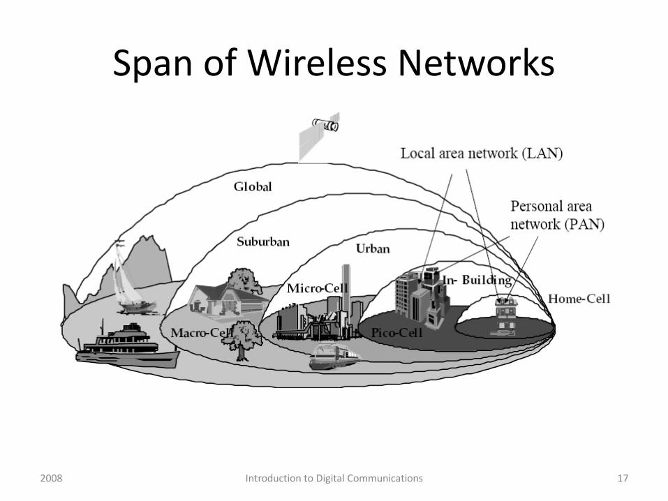
Span of Wireless Networks
Introduction to Digital Communications 172008

18
GSM Mobile Phone
Transmitter
Receiver

19
CDMA Cell Phone
Mobile phone transmitter
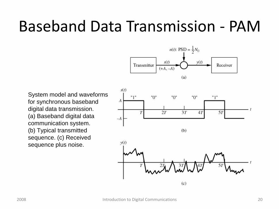
Baseband Data Transmission - PAM
System model and waveforms
for synchronous baseband
digital data transmission.
(a) Baseband digital data
communication system.
(b) Typical transmitted
sequence. (c) Received
sequence plus noise.
20Introduction to Digital Communications2008
• Each T second pulse represents a bit of data
• Receiver has to decide whether a 1 or 0 was received (A or –A)
• Integrate-and-dump detector
21Introduction to Digital Communications2008
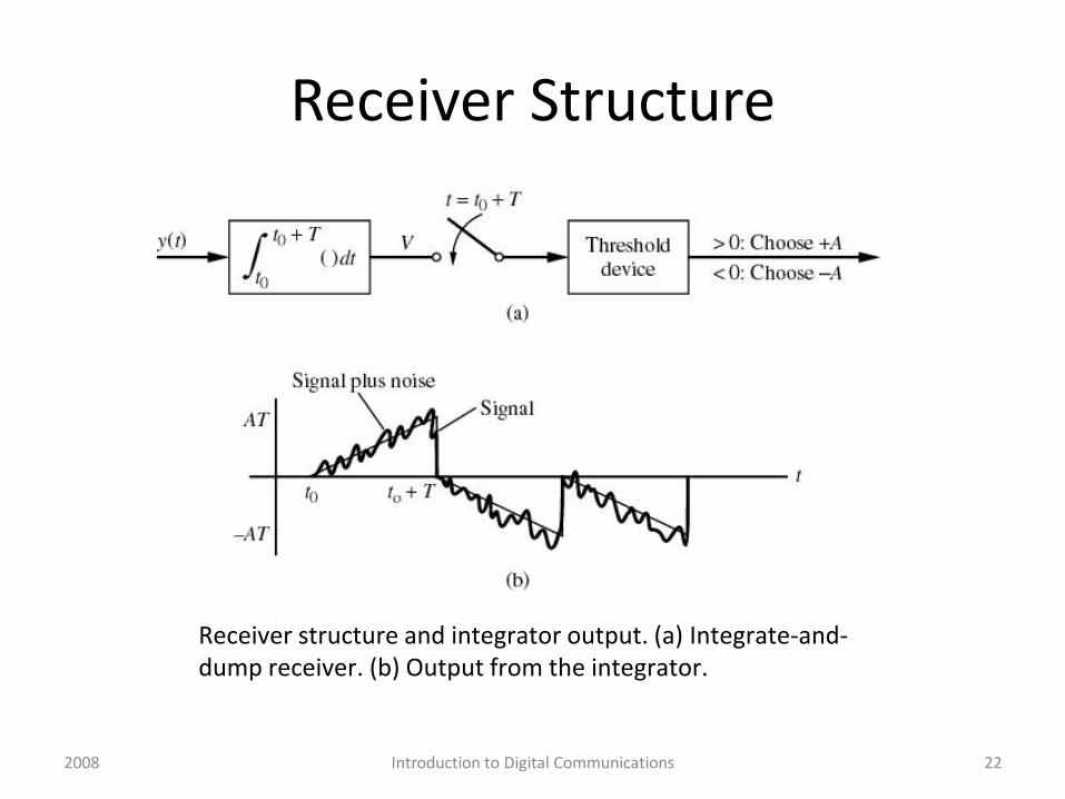
Receiver Structure
Receiver structure and integrator output. (a) Integrate-and-dump receiver. (b) Output from the integrator.
22Introduction to Digital Communications2008
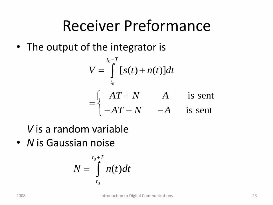
Receiver Preformance• The output of the integrator is
V is a random variable• N is Gaussian noise
0
0
[ ( ) ( )]
is sent
is sent
t T
t
V s t n t dt
AT N A
AT N A
0
0
( )
t T
t
N n t dt
23Introduction to Digital Communications2008

2005-01-21 Lecture 1 24
Noise in communication systems
Thermal noise is described by a zero-mean Gaussian random process, n(t).
Its PSD is flat, hence, it is called white noise
N0/2 W/Hz
Probability density function
Power spectral density
2 2/(2 )
2( )
2
n
N
ef n

Analysis
since AWGN is uncorrelated
2)(
2
)]()([
)(][
][][][
0)]([])([][
00
2
2
22
0
0
0
0
0
0
0
0
0
0
0
0
0
0
TNdtdsst
N
dtdssntnE
dttnENE
NENENVar
dttnEdttnENE
Tt
t
Tt
t
Tt
t
Tt
t
Tt
t
Tt
t
Tt
t
25Introduction to Digital Communications2008
Error Analysis
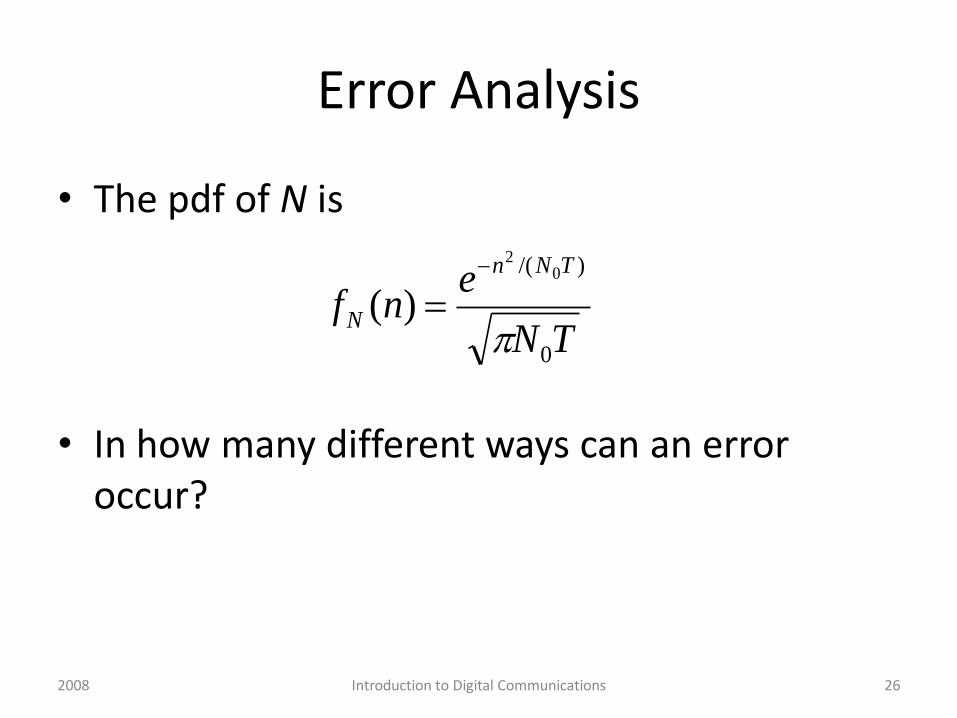
• The pdf of N is
• In how many different ways can an error occur?
TN
enf
TNn
N
0
)/( 02
)(
26Introduction to Digital Communications2008
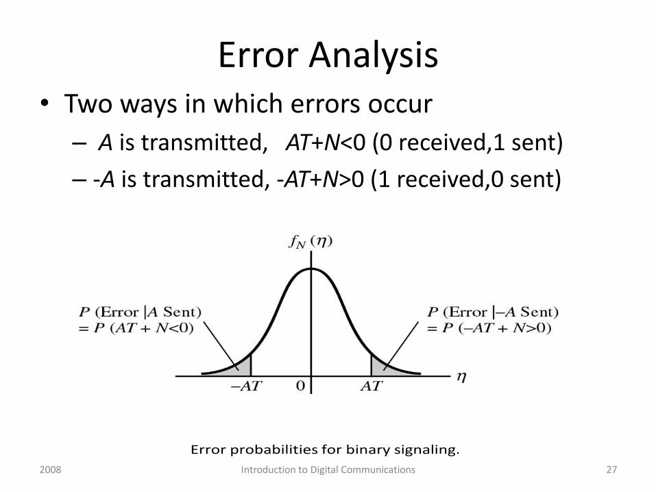
Error Analysis• Two ways in which errors occur
– A is transmitted, AT+N<0 (0 received,1 sent)
– -A is transmitted, -AT+N>0 (1 received,0 sent)
Error probabilities for binary signaling.
27Introduction to Digital Communications2008
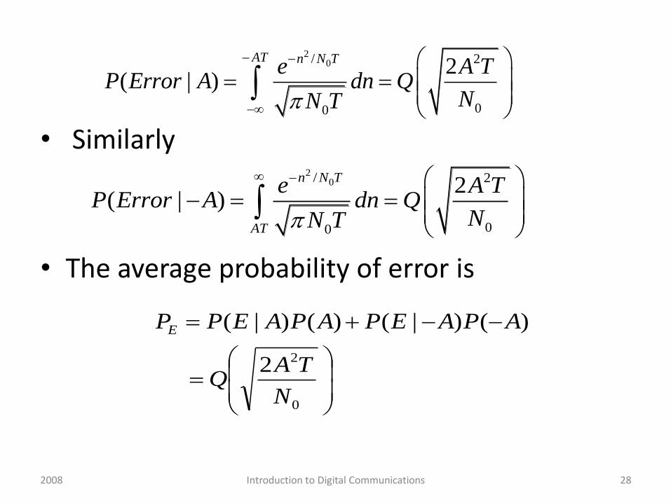
• Similarly
• The average probability of error is
20/ 2
00
2( | )
AT n N Te A T
P Error A dn QNN T
20/ 2
00
2( | )
n N T
AT
e A TP Error A dn Q
NN T
0
22
)()|()()|(
N
TAQ
APAEPAPAEPPE
28Introduction to Digital Communications2008
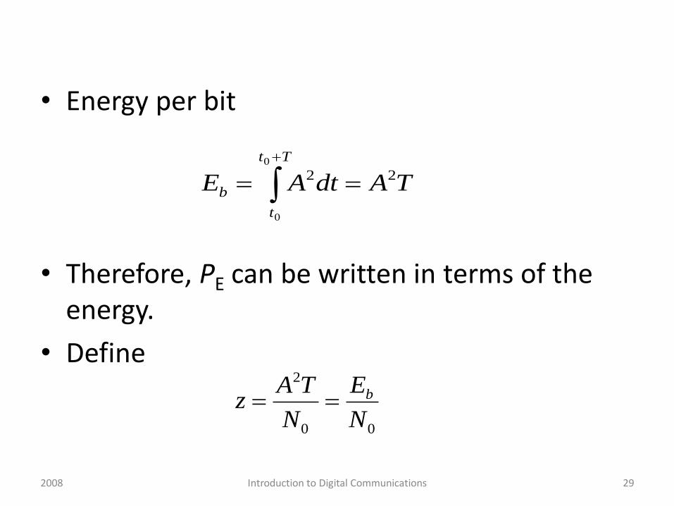
• Energy per bit
• Therefore, PE can be written in terms of the energy.
• Define
TAdtAE
Tt
t
b
220
0
00
2
N
E
N
TAz b
29Introduction to Digital Communications2008
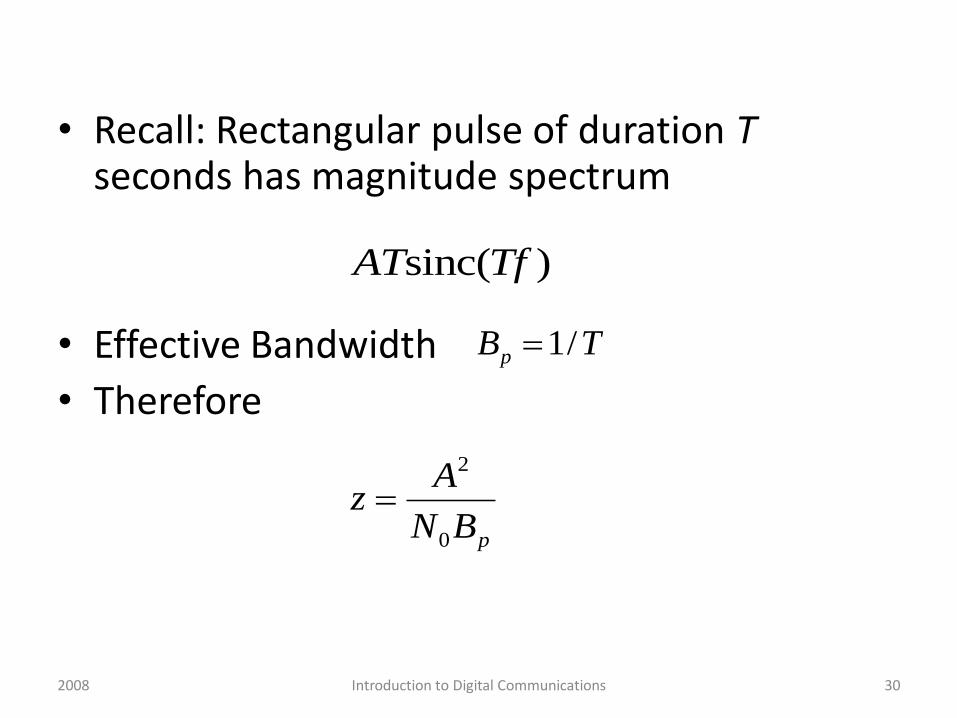
• Recall: Rectangular pulse of duration Tseconds has magnitude spectrum
• Effective Bandwidth
• Therefore
TBp /1
pBN
Az
0
2
sinc( )AT Tf
30Introduction to Digital Communications2008
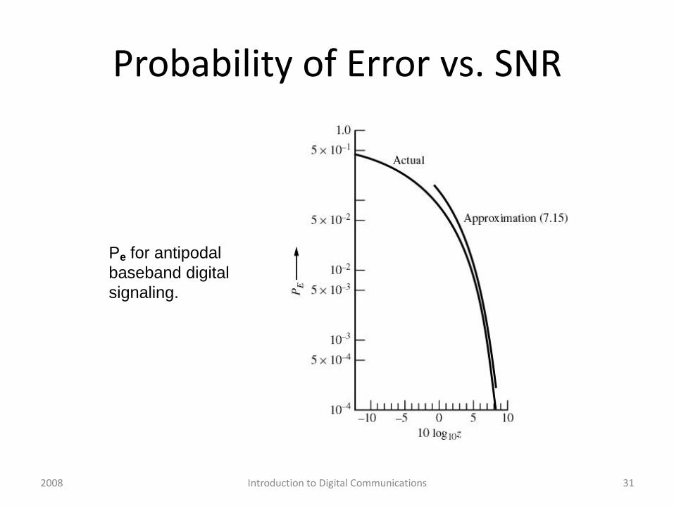
Probability of Error vs. SNR
Pe for antipodal
baseband digital
signaling.
31Introduction to Digital Communications2008
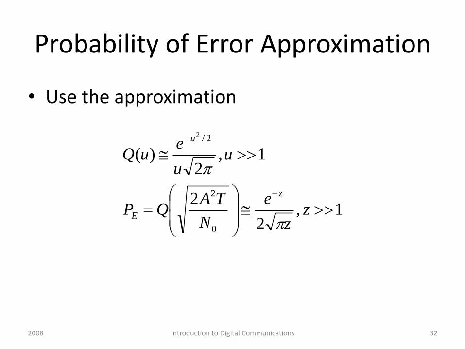
Probability of Error Approximation
• Use the approximation
1,2
2
1,2
)(
0
2
2/2
zz
e
N
TAQP
uu
euQ
z
E
u
32Introduction to Digital Communications2008
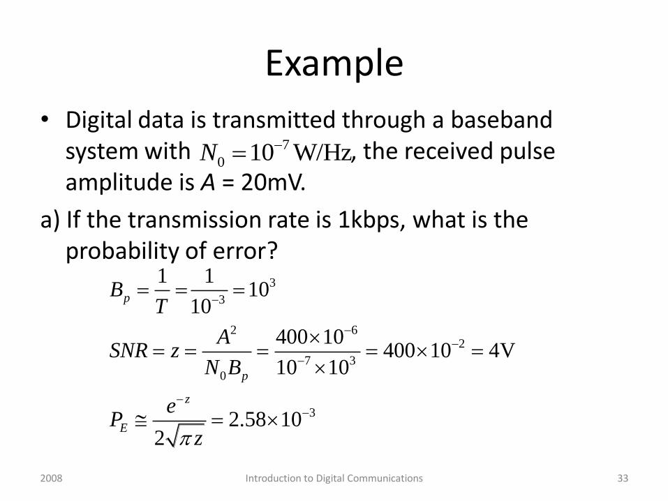
Example
• Digital data is transmitted through a baseband system with , the received pulse amplitude is A = 20mV.
a) If the transmission rate is 1kbps, what is the probability of error?
3
3
2 62
7 3
0
3
1 110
10
400 10400 10 4V
10 10
2.58 102
p
p
z
E
BT
ASNR z
N B
eP
z
7
0 10 W/HzN
33Introduction to Digital Communications2008
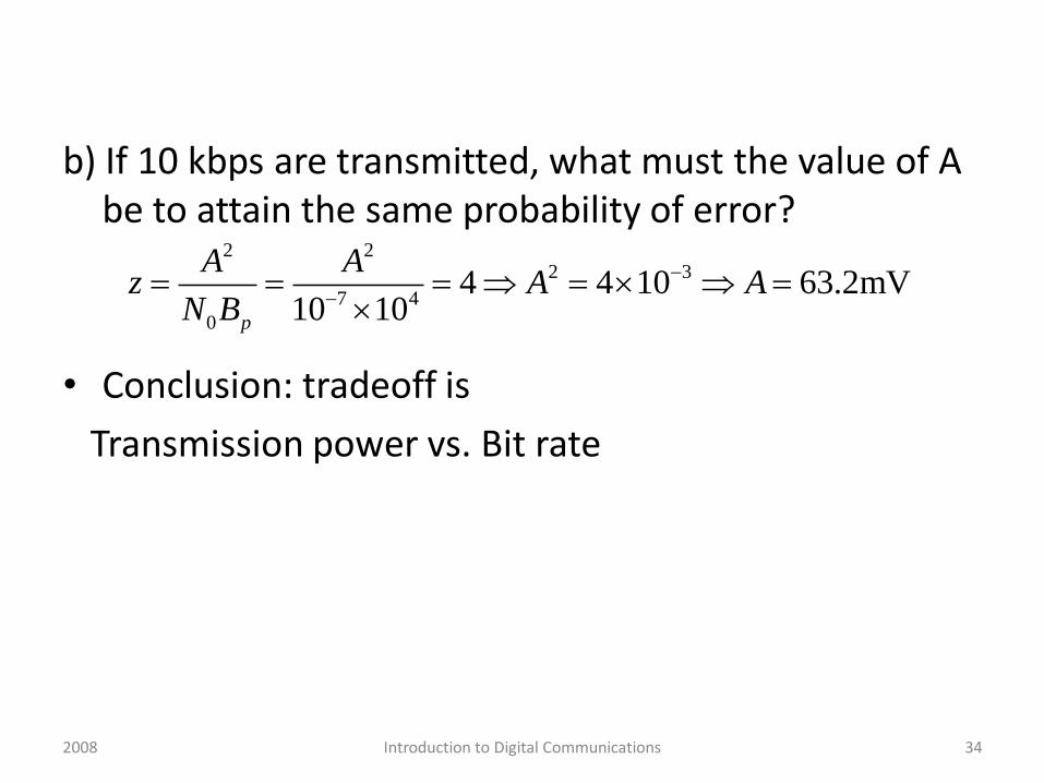
b) If 10 kbps are transmitted, what must the value of A be to attain the same probability of error?
• Conclusion: tradeoff is
Transmission power vs. Bit rate
2 22 3
7 4
0
4 4 10 63.2mV10 10p
A Az A A
N B
34Introduction to Digital Communications2008
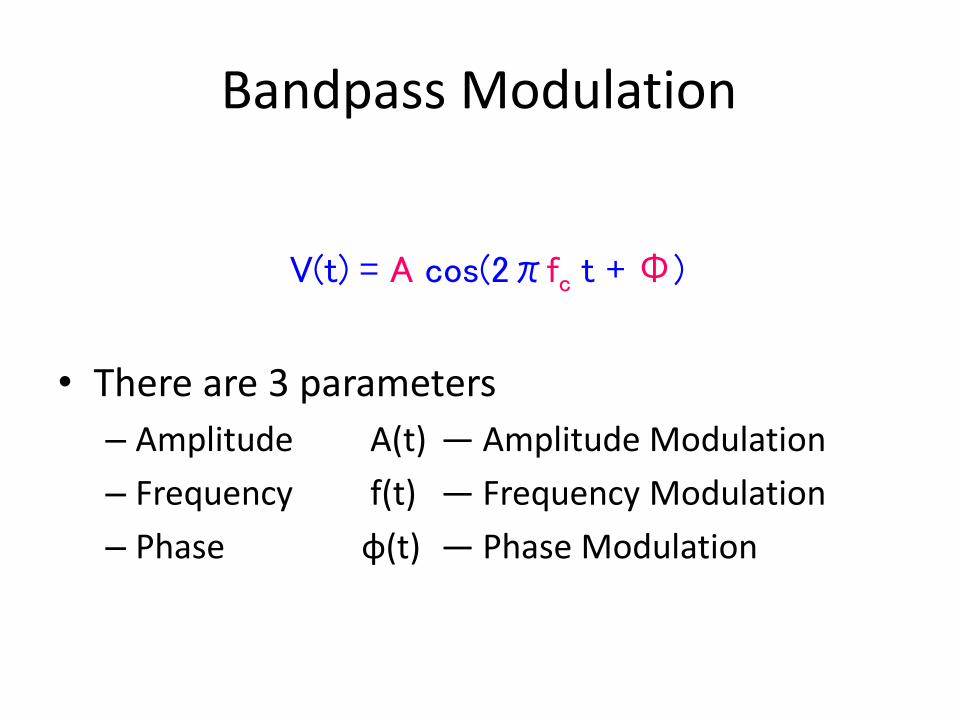
Bandpass Modulation
• There are 3 parameters
– Amplitude A(t) ― Amplitude Modulation
– Frequency f(t) ― Frequency Modulation
– Phase φ(t) ― Phase Modulation
V(t) = A cos(2πfc t + Φ)
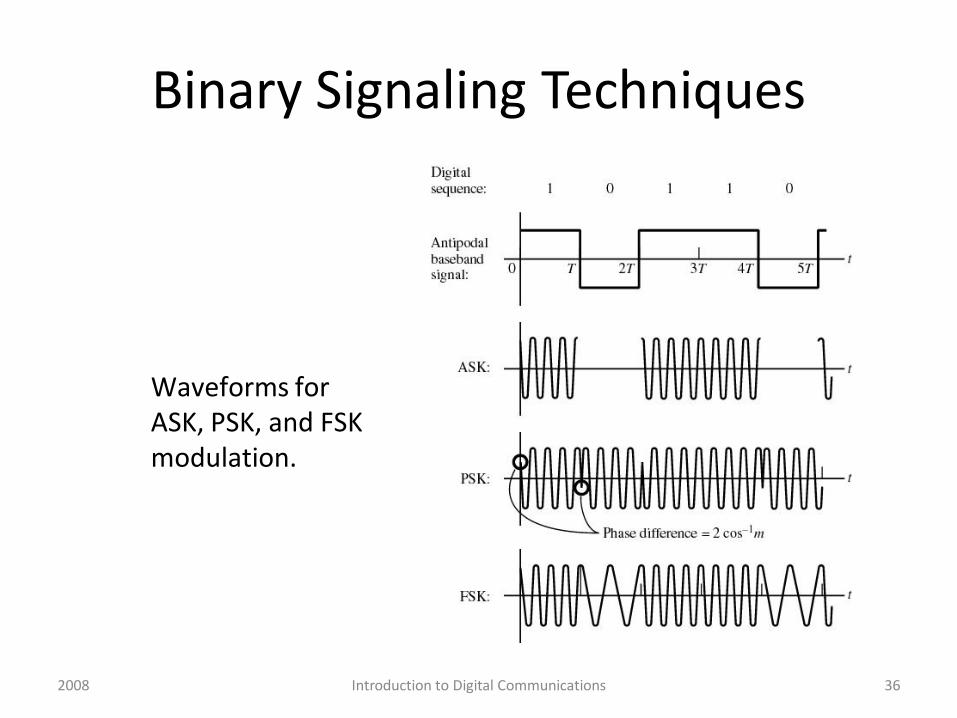
Binary Signaling Techniques
Waveforms forASK, PSK, and FSK modulation.
36Introduction to Digital Communications2008
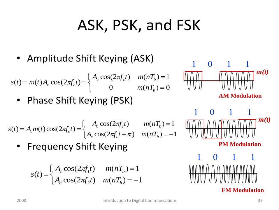
ASK, PSK, and FSK
• Amplitude Shift Keying (ASK)
• Phase Shift Keying (PSK)
• Frequency Shift Keying
0)(0
1)()2cos()2cos()()(
b
bcc
ccnTm
nTmtfAtfAtmts
1)()2cos(
1)()2cos()2cos()()(
bcc
bcc
ccnTmtfA
nTmtfAtftmAts
1)()2cos(
1)()2cos()(
2
1
bc
bc
nTmtfA
nTmtfAts
1 0 1 1
1 0 1 1
1 0 1 1
AM Modulation
PM Modulation
FM Modulation
m(t)
m(t)
37Introduction to Digital Communications2008
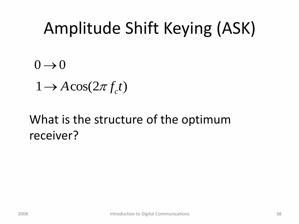
Amplitude Shift Keying (ASK)
What is the structure of the optimum receiver?
1 cos(2 )cA f t
0 0
38Introduction to Digital Communications2008

Receiver for Binary Signals in Noise
Receiver structure for detecting binary signals in additive white Gaussian noise (AWGN)
39Introduction to Digital Communications2008
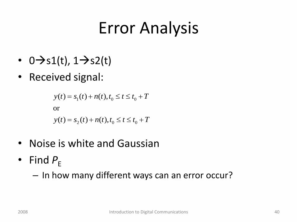
Error Analysis
• 0s1(t), 1s2(t)
• Received signal:
• Noise is white and Gaussian
• Find PE
– In how many different ways can an error occur?
1 0 0
2 0 0
( ) ( ) ( ),
or
( ) ( ) ( ),
y t s t n t t t t T
y t s t n t t t t T
40Introduction to Digital Communications2008
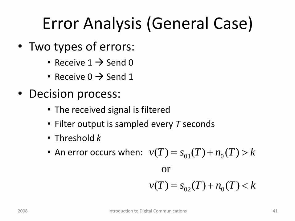
Error Analysis (General Case)• Two types of errors:
• Receive 1 Send 0
• Receive 0 Send 1
• Decision process: • The received signal is filtered
• Filter output is sampled every T seconds
• Threshold k
• An error occurs when:
kTnTsTv
kTnTsTv
)()()(
or
)()()(
002
001
41Introduction to Digital Communications2008
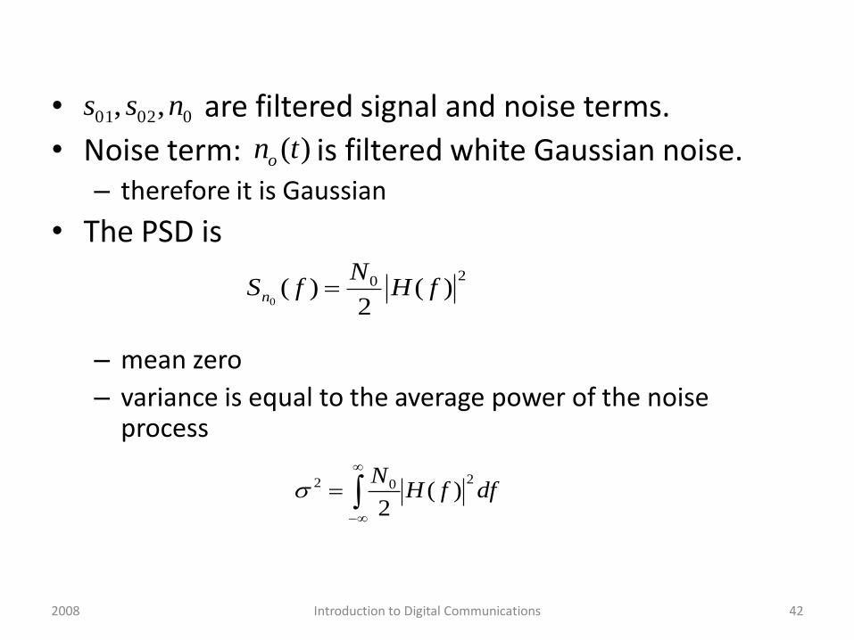
• are filtered signal and noise terms.
• Noise term: is filtered white Gaussian noise.– therefore it is Gaussian
• The PSD is
– mean zero
– variance is equal to the average power of the noise process
00201 ,, nss
20 )(2
)(0
fHN
fSn
dffHN 202 )(2
( )on t
42Introduction to Digital Communications2008
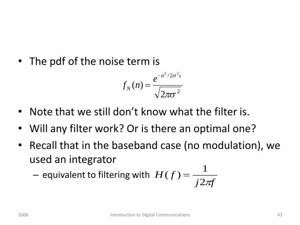
• The pdf of the noise term is
• Note that we still don’t know what the filter is.
• Will any filter work? Or is there an optimal one?
• Recall that in the baseband case (no modulation), we used an integrator
– equivalent to filtering with
2
2/
2)(
022
n
N
enf
fjfH
2
1)(
43Introduction to Digital Communications2008
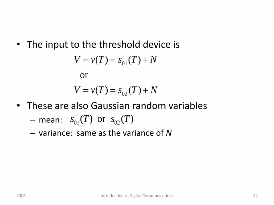
• The input to the threshold device is
• These are also Gaussian random variables
– mean:
– variance: same as the variance of N
01
02
( ) ( )
or
( ) ( )
V v T s T N
V v T s T N
01 02( ) or ( )s T s T
44Introduction to Digital Communications2008
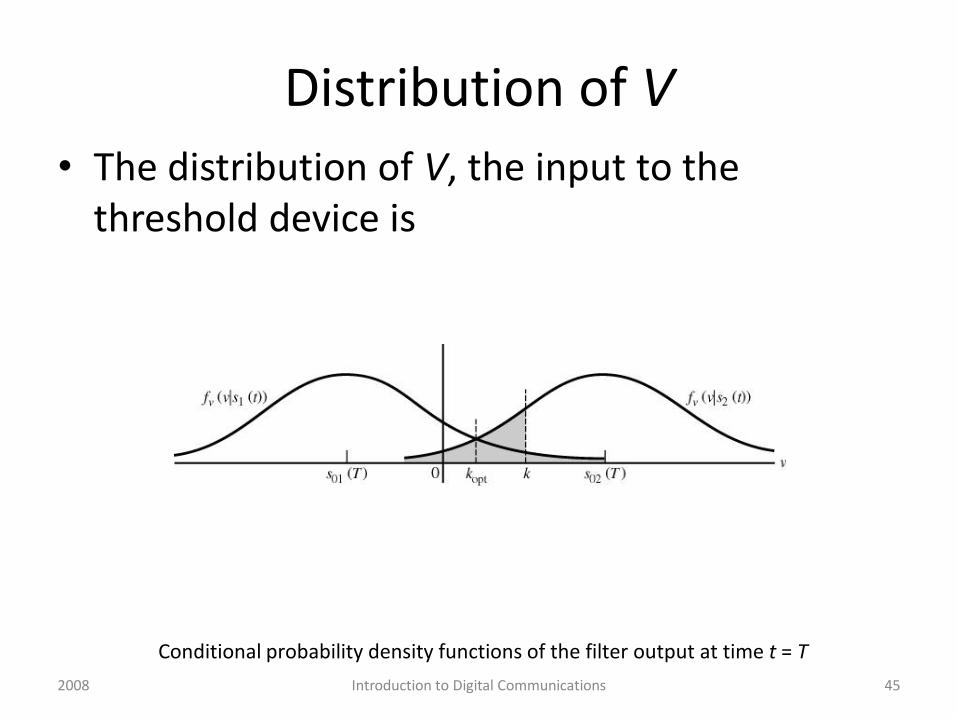
Distribution of V
• The distribution of V, the input to the threshold device is
Conditional probability density functions of the filter output at time t = T
45Introduction to Digital Communications2008
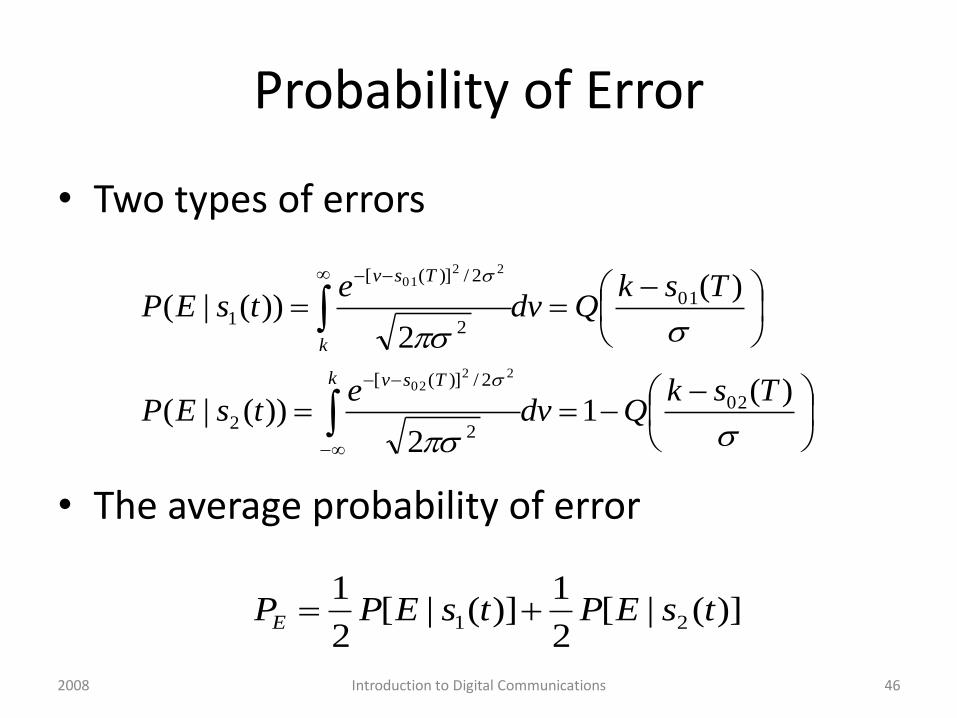
Probability of Error
• Two types of errors
• The average probability of error
)(1
2))(|(
)(
2))(|(
02
2
2/)]([
2
01
2
2/)]([
1
2202
2201
TskQdv
etsEP
TskQdv
etsEP
k Tsv
k
Tsv
)](|[2
1)](|[
2
121 tsEPtsEPPE
46Introduction to Digital Communications2008
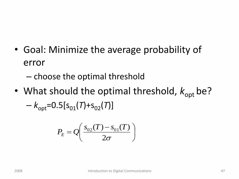
• Goal: Minimize the average probability of error
– choose the optimal threshold
• What should the optimal threshold, kopt be?
– kopt=0.5[s01(T)+s02(T)]
2
)()( 0102 TsTsQPE
47Introduction to Digital Communications2008
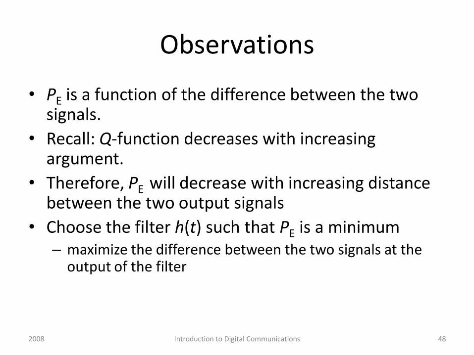
Observations
• PE is a function of the difference between the two signals.
• Recall: Q-function decreases with increasing argument.
• Therefore, PE will decrease with increasing distance between the two output signals
• Choose the filter h(t) such that PE is a minimum– maximize the difference between the two signals at the
output of the filter
48Introduction to Digital Communications2008
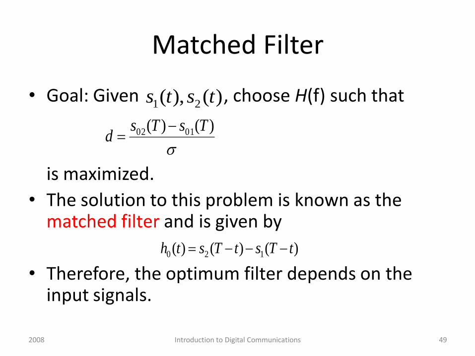
Matched Filter
• Goal: Given , choose H(f) such that
is maximized.
• The solution to this problem is known as the matched filter and is given by
• Therefore, the optimum filter depends on the input signals.
)(),( 21 tsts
)()( 0102 TsTsd
)()()( 120 tTstTsth
49Introduction to Digital Communications2008
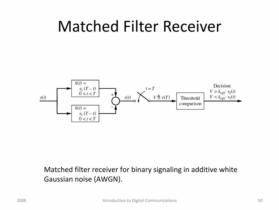
Matched Filter Receiver
Matched filter receiver for binary signaling in additive white Gaussian noise (AWGN).
50Introduction to Digital Communications2008
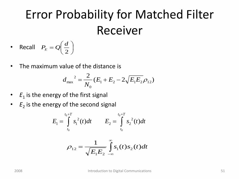
Error Probability for Matched Filter Receiver
• Recall
• The maximum value of the distance is
• E1 is the energy of the first signal
• E2 is the energy of the second signal
2
dQPE
)2(2
122121
0
2
max EEEEN
d
dttstsEE
)()(1
21
21
12
51Introduction to Digital Communications
0 0
0 0
2 2
1 1 2 2( ) ( )
t T t T
t t
E s t dt E s t dt
2008
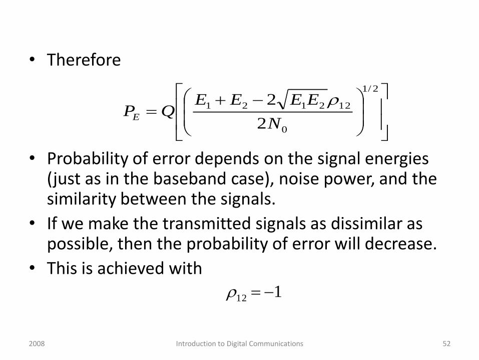
• Therefore
• Probability of error depends on the signal energies (just as in the baseband case), noise power, and the similarity between the signals.
• If we make the transmitted signals as dissimilar as possible, then the probability of error will decrease.
• This is achieved with
2/1
0
122121
2
2
N
EEEEQPE
112
52Introduction to Digital Communications2008

ASK
• The matched filter:
• Optimum Threshold:
• Similarity between signals?
• Therefore
• 3dB worse than baseband.
)2cos()(,0)( 21 tfAtsts c
)2cos( tfA c
TA2
4
1
zQN
TAQPE
0
2
4
53Introduction to Digital Communications2008

PSK
• Modulation index: m (determines the phase shift)
• Matched Filter with threshold 0
• For m = 0, 3dB better than ASK
)cos2sin()(
)cos2sin()(
1
2
1
1
mtfAts
mtfAts
c
c
)2cos(12 2 tfmA c
))1(2( 2 zmQPE
54Introduction to Digital Communications2008
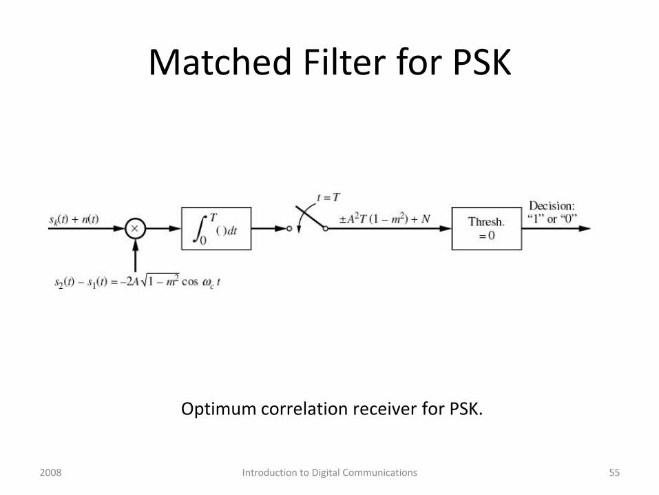
Matched Filter for PSK
Optimum correlation receiver for PSK.
55Introduction to Digital Communications2008

FSK
•
• Probability of error:
• Same as ASK
))(2cos()(
)2cos()(
2
1
tffAts
tfAts
c
c
T
mf
)( zQ
56Introduction to Digital Communications2008


