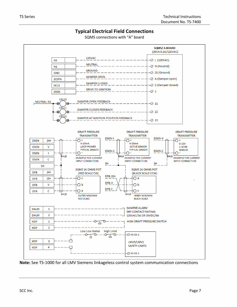
SCC Inc. Technical Instructions
Document No. TS-7400 March 19, 2021
SCC Inc.
Introduction to Draft Control
A TS… touchscreen kit base package without annunciation, with draft control is suited for Firetube
and Watertube boilers, as a stand-alone stack draft control.
Dynamic graphical display of stack draft pressures provides the operators with visual aid for
operation monitoring
Continuous display of actual stack pressure and setpoint provides monitoring the difference to
identify potential stack draft issues
PID control provides accurate draft pressures for any firing rates or stack pressures
Continuous stack pressure monitoring plus actuator position feedback provides an accurate control
and monitoring process.
Siemens differential pressure transmitter can cover any draft pressure measurement range. For
example: -3.00 to 3.0 IWC. -5.00 to 5.00 IWC, and -10 to 10 IWC
SCC differential pressure transmitter pre-spanned for fixed range (pages 3 - 4).
Stack damper position monitoring and display. With alarms for open, ignition and closed positions.
Modbus communication to Siemens LMV linkageless control provides minimum field wiring.
Can be used as universal draft control system with third party burner controls.
Modbus TCP/IP for BMS communication
UL 378 listed
Technical Instructions TS Series
Document No. TS-7400
Page 2 SCC Inc.
Base Draft Control Main Parts
Name Related Documents
Touchscreen and control panels TS-1000, TS-4000, TS-5000
SQM5 actuator 155.517P25
SQM5 coupling CPBK-1000
SQM5 mounting bracket CPBK-2000
TS Series Technical Instructions
Document No. TS-7400
SCC Inc. Page 3
Draft Control Panel Builder
The touchscreen control panel with draft control is comprised of few components in addition to the
TS control panel itself. Use the following pages to choose the components needed for your specific
application. See TS-1000, TS-4000 or TS-5000 part number selection charts for your complete
application.
Auxiliary Components
Base Unit – Qty (1) Required
Draft Control Base Package Option. See TS-1000 for all available options
TS-3DXS-1XX
Draft control panel PLC based and 3”
touchscreen with LMV communication, and no
burner boiler annunciation or analog inputs
TS-6DXS-1XX
Draft control panel PLC based and 6”
touchscreen with LMV communication, and no
burner boiler annunciation or analog inputs
Differential Pressure Transmitter – Qty (1) Required
Option 1 - One differential pressure transmitter is required per draft control system. Refer to TS-
1000/TS-4000/TS-5000 for electrical connections.
7MF0340-1CA22-
1NC6-Z+A02+B21
4-20 mA Siemens differential pressure
transmitter, 0-25 IWC, could be spanned to any
measurement variations from negative to
positive within the measurement range of 25
IWC
Technical Instructions TS Series
Document No. TS-7400
Page 4 SCC Inc.
Auxiliary Components (continued)
Option 2 - One differential pressure transmitter is required per draft control system. Refer to TS-
1000/TS-4000/TS-5000 for specific SCC control system electrical connections with draft control.
SCC Differential Pressure Transmitter w/o Display
TS-DPA-020X
4-20 mA, no display
-2.00 to 2.00 IWC
TS-DPA-025X
4-20 mA, no display
-2.5 to 2.5 IWC
TS-DPA-030X
4-20 mA, no display
-3.0 to 3.0 IWC
TS-DPA-040X 4-20 mA, no display
-4.00 to 4.0 IWC
TS-DPA-050X 4-20 mA, no display
5.00 to 5.00 IWC
TS-DPA-100X
4-20 mA, no display
-10.0 to 10.0 IWC
SCC Differential Pressure Transmitter w/ Display
TS-DPA-020D
4-20 mA, with display
-2.00 to 2.00 IWC
TS-DPA-025D
4-20 mA, with display
-2.5 to 2.5 IWC
TS Series Technical Instructions
Document No. TS-7400
SCC Inc. Page 5
TS-DPA-030D
4-20 mA, with display
-3.0 to 3.0 IWC
TS-DPA-040D 4-20 mA, with display
-4.00 to 4.0 IWC
TS-DPA-050D 4-20 mA, with display
5.00 to 5.00 IWC
TS-DPA-100D
4-20 mA, with display
-10.0 to 10.0 IWC
SCC Differential Pressure Switch
TS-1910-1
0.4 to 1.6 IWC
TS-1910-5 1.4 to 5.5 IWC
TS-1910-10 3.0 to 11.75 IWC
Technical Instructions TS Series
Document No. TS-7400
Page 6 SCC Inc.
Auxiliary Components (continued)
Coupling – Qty (1) Required
Zero-lash, flexible couplings are available for each SQM5 actuator. Refer to document No. CPBK-
1000 for details. Select the characters from the included part number tree to replace the “x’s” as
appropriate for your damper and actuator.
CxE6SCA-xxRSA Flexible couplings for SQM45… actuators
SQM5 Damper Rotary Actuator
SQM5 rotary actuator. Refer to document No. 155.517P25 for complete SQM5 part number legend.
Select the characters from the tree below to replace the “x’s” as appropriate for your actuator.
SQM5xx64R1A3x SQM5 rotary actuator
SQM5 Damper Rotary Actuator
SQM5 bracket. Refer to document No. CPBK-2000 for details. Select the characters from the
included part number tree below to replace the “x’s” as appropriate for your bracket.
BR-AS21-x4-x-HT SQM5 bracket assembly
TS Series Technical Instructions
Document No. TS-7400
SCC Inc. Page 7
Typical Electrical Field Connections SQM5 connections with “A” board
Note: See TS-1000 for all LMV Siemens linkageless control system communication connections
Technical Instructions TS Series
Document No. TS-7400
Page 8 SCC Inc.
Typical Piping and Installation
TS Series Technical Instructions
Document No. TS-7400
SCC Inc. Page 9
Typical Piping and Installation (continued)
Technical Instructions TS Series
Document No. TS-7400
Page 10 SCC Inc.
Typical Piping and Installation (continued)
TS Series Technical Instructions
Document No. TS-7400
SCC Inc. Page 11
Typical Piping and Installation (continued)
Piping and Installation (Furnace Back Pressure Piping)
TS Series Technical Instructions
Document No. TS-7400
SCC Inc. Page 13
Piping and Installation (continued)
Technical Instructions TS Series
Document No. TS-7400
Page 14 SCC Inc.
Piping and Installation (continued)
TS Series Technical Instructions
Document No. TS-7400
SCC Inc. Page 15
Draft Control Base Package Parts Description
A BMS Communication
BACnet/LON/N2/RTU
BMS communication other than
Modbus TCP/IP I
120 VAC SPDT
Relays
Burner / Boiler alarms ,13
annunciation relays, 3 relays
for draft(optional), first in
first out.
B Solid State Relays
(Draft Control Option)
Draft damper open and close
relays J
Modbus RS232
and RS485
Terminals
Field Modbus connections to
LMV5/LMV3/RWF55/ RWF10
C
DPDT Relays
(Draft Control Option
Only)
Draft control ignition permissive
Draft control damper drive open
on faliure
Draft control alarm
AG Analog Input
Terminals
Field wiring terminals for
flow, pressure, temperature,
DP pressure, 4-20mA, or 0-10
Volt inputs.
D 24 VDC Terminals 24 VDC connections T Draft Mod Motor
Field Terminals Ignition permissive
E 24 VDC Power Supply 24VDC source W 1 Amp Circuit
Breaker
Draft control 120 VAC power
isolation
F Field Terminals
(Yellow)
Field outputs and control
terminals X
120VAC Power
Terminals
SQM5 actuator 120VAC
power terminals
G 3 Amps Circuit
Breaker 120 VAC power isolation Y Off Delay Timer
Draft control, high pressure
boiler shutoff, delay timer
H 16 Amp Non-Fused
Disconnect
120 VAC disconnect, only when
installed in SCC enclosure Z
Draft Control
Terminals
LMV interconnect safety loop
and high pressure switch
terminals
Note: AF Module only used when the AZL is installed more than 15 feet from the Touchscreen.
Technical Instructions TS Series
Document No. TS-7400
Page 16 SCC Inc.
Dimensions
Dimensions in inches; millimeters in brackets
16” X 16” X 8” Stack Draft Enclosure (Base Package)
TS Series Technical Instructions
Document No. TS-7400
SCC Inc. Page 17
SQM5 Product Number Identification Legend
For actuator identification only. To select product numbers for ordering, see Table 1.
Figure 1. SQM5… Product Number Identification Legend.
SQM5 0 . 4 6 4 R 1 A 3 R
Actuator family
Torque in-lb @ 60 (50) Hz.
0 90 for 8 (10) sec. running time
0 140 for 12 (15), 25 (30), 37 (45) sec.
3 200 for 25 (30) sec.
6 310 for 37 (45) sec.
6 400 for 50 (60), 75 (90)sec.
Running time for 90°
Not all actuator running times are
available in each torque.
Refer to table 1
60 Hz. 50 Hz.
2 8 sec. 2 10 sec.
3 12 sec. 3 15 sec.
4 25 sec. 4 30 sec.
5 37 sec. 5 45 sec.
6 50 sec. 6 60 sec.
Number of SPDT switches
6 2 limit and 4 auxiliary switches
Shaft selection
0 no shaft (shaft must be ordered separately)
1 round 10 mm, single ended (for use with VKF41... butterfly valves)
4 square 3/8 inch, dual ended
5 D-shaped 10mm, single ended
7 round 14 mm, single ended
Approvals
R UL recognized, CSA certified
Operating voltage (Vac @50-60 Hz)
1 110-120 Vac
2 220-240 Vac
8 24 Vac
Internal circuit board (SQM5x.xxxxx G, H, K , Zx actuators require potentiometer ASZ…)
A AGA56.1A97 (position proportional control)
G AGA56.41A... (4 to 20 mA input)
H AGA56.42A... (0 to 135 Ohm input)
K AGA56.43A... (0 to 10 Vdc input)
Z AGA56.9... (all inputs/outputs, linearization, split ranging, override and pre-set positioning)
Potentiometer (1000 Ohm required when using SQM5x.xxxxx G, H, K, Zx actuators)
3 ASZ12.30 (1000 ohm, 90°)
4 ASZ12.33 (1000 Ohm, 135°)
7 ASZ22.30 (1000/1000 Ohm, 90°)
8 ASZ22.33 (1000/1000 Ohm, 135°)
B ASZ16.703 (135 Ohm, 90°)
C ASZ16.733 (135 Ohm, 135°)
L ASZ66.733 (135/135 Ohm, 135°)
Rotational Direction (Product numbers ending without R are ccw)
R Clockwise (when facing gear end. See Figure 6 .)
Technical Instructions TS Series
Document No. TS-7400
Page 18 SCC Inc.
Touchscreen Kit with Draft control part number legend
TS - 0 D 8 B - 2 5 W
Touchscreen
Touchscreen Size
3 = 3" touchscreen
6 = 6" touchscreen
0 = 10" touchscreen
C = 3" touchscreen mounted > 15 ft. away from AZL (LMV5 only)
F = 6” touchscreen mounted > 15 ft. away from AZL (LMV5 only)
J = 10" touchscreen mounted > 15 ft. away from AZL (LMV5 only)
Draft Control
X = No draft control included
D = Draft control
Annunciation and Monitoring Options
X = No annunciation inputs
1 = Standard annunciation, 13 120VAC inputs
2 = 13 120VAC annunciation inputs, and 4 analog inputs
3 = 13 120 VAC annunciation inputs, and 4 RTD 1000 Ohm inputs
4 = 13 120 VAC annunciation inputs, and 4 RTD 1000 Ohm inputs
dedicated for Economizer
5 = 13 120 VAC annunciation inputs, 4 analog inputs, and 4 RTD 1000 Ohm inputs
6 = 13 120 VAC annunciation inputs, 4 analog inputs, and 4 RTD 1000 Ohm inputs
dedicated for economizer
7 = 13 120 VAC annunciation inputs, 4 RTD 1000 Ohm inputs, and 4 RTD 1000
Ohm inputs dedicated for economizer
8 = 13 120 VAC annunciation inputs, 4 analog inputs, and 4 RTD 1000 Ohm inputs, and 4 RTD
1000 Ohm inputs dedicated for economizer
Building Management Interface (BMS)
S = Standard, Modbus TCP/IP
B = BACnet / IP, or Ethernet / IP
M = BACnet MS/TP, Modbus RTU, or Metasys N2
L = LonWorks
N = Profinet
P = Profibus
Enclosure Option
X = No - din rail kit on plate to be mounted into enclosure (Mounted by others)
1 = NEMA 1
2 = NEMA 12, includes cover over touchscreen and AZL/RWF (if applicable)
4 = NEMA 4X (indoor), includes cover over AZL/RWF (if applicable)
A = NEMA 1 with cooling fan
B = NEMA 12 with cooling fan, includes cover over touchscreen and AZL/RWF and fan (if applicable)
C = NEMA 4X with cooling fan, includes cover over touchscreen and AZL/RWF and fan (if applicable)
6 = NEMA 1, with manual rest Warrick relay
7 = NEMA 12, includes cover over touchscreen and AZL/RWF (if applicable), with manual reset Warrick relay
9 = NEMA 4X (indoor), includes cover over AZL/RWF (if applicable), with manual reset Warrick relay
F = NEMA 1 with cooling fan, with manual reset Warrick relay
G = NEMA 12 with cooling fan, includes cover over touchscreen, AZL/RWF, and fan (if applicable), with
manual reset Warrick relay
K = NEMA 4X with cooling fan, includes cover over touchscreen, AZL/RWF, and fan (if applicable), with
manual reset Warrick relay
AZL (Option only with enclosure)
X = No AZL included (Must be selected with din rail kit on plate)
3 = AZL23.00A9 mounted to front of enclosure
5 = AZL52.40B1 mounted to front of enclosure
RWF (Option only with enclosure)
X = No RWF included
L = RWF55.50A9 for external load control
W = RWF55.50A9 for water level control with transformer
2 = (2) RWF55.50A9 for external load control and water level control - includes 1 transformer
TS Series Technical Instructions
Document No. TS-7400
SCC Inc. Your feedback is important to us. If you have Document No. TS-7400
1250 Lunt Avenue comments about this document, please send them Country of Origin: US
Elk Grove Village, IL 60007 to [email protected] Page 19
U.S.A.
Approvals
Information in this publication is based on current specifications. The company reserves the right to make changes in specifications and models as design improvements are introduced. Product or company names mentioned herein may be the trademarks of their respective owners. © 2020 SCC Inc.