35
INTRODUCTION TO FFAGs M.K.Craddock Department of Physics and Astronomy, University of British Columbia & TRIUMF FFAG'08 workshop, Manchester, 1st - 5th September 2008
INTRODUCTION TO FFAGs
M.K.Craddock
Department of Physics and Astronomy, University of British Columbia
& TRIUMF
FFAG'08 workshop, Manchester, 1st - 5th September 2008
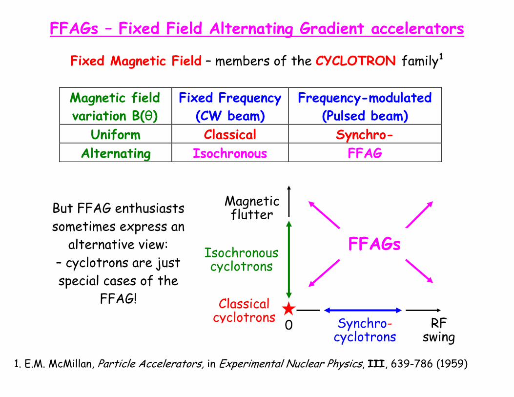
FFAGs – Fixed Field Alternating Gradient accelerators
Fixed Magnetic Field – members of the CYCLOTRON family1
Magnetic field variation B(θ)
Fixed Frequency (CW beam)
Frequency-modulated (Pulsed beam)
Uniform Classical Synchro-
Alternating Isochronous FFAG
But FFAG enthusiasts sometimes express an
alternative view: – cyclotrons are just special cases of the
FFAG!
Magnetic flutter
Synchro- cyclotrons
Classical cyclotrons 0
FFAGs Isochronous cyclotrons
RF swing
1. E.M. McMillan, Particle Accelerators, in Experimental Nuclear Physics, III, 639-786 (1959)
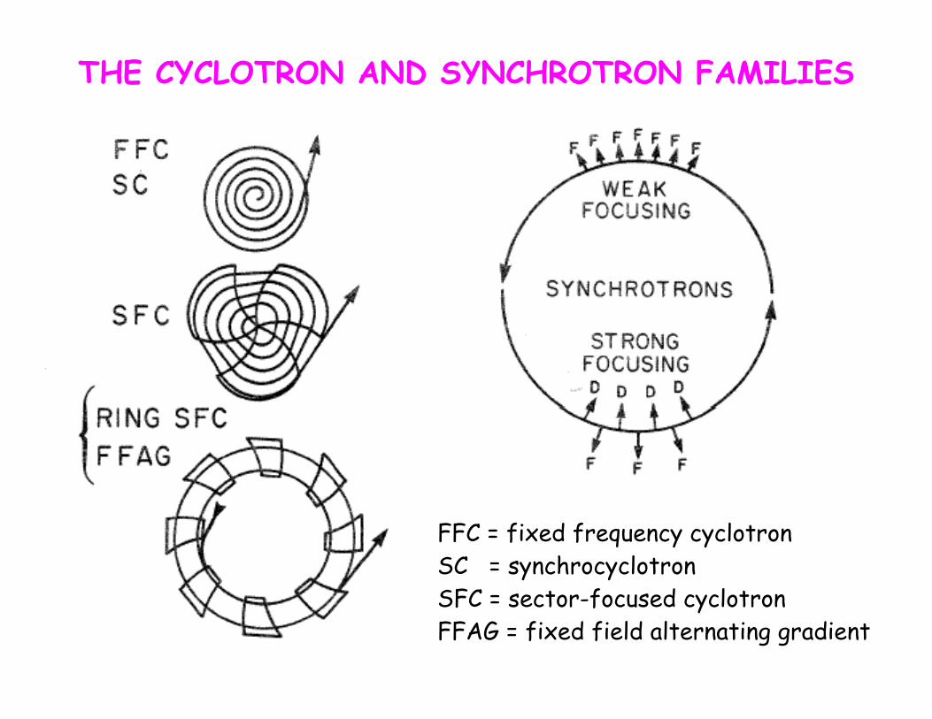
THE CYCLOTRON AND SYNCHROTRON FAMILIES
FFC = fixed frequency cyclotron SC = synchrocyclotron SFC = sector-focused cyclotron FFAG = fixed field alternating gradient
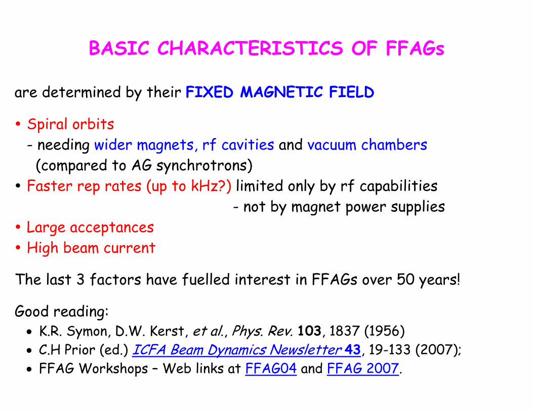
BASIC CHARACTERISTICS OF FFAGs
are determined by their FIXED MAGNETIC FIELD
Spiral orbits - needing wider magnets, rf cavities and vacuum chambers (compared to AG synchrotrons)
Faster rep rates (up to kHz?) limited only by rf capabilities - not by magnet power supplies
Large acceptances High beam current
The last 3 factors have fuelled interest in FFAGs over 50 years!
Good reading: • K.R. Symon, D.W. Kerst, et al., Phys. Rev. 103, 1837 (1956) • C.H Prior (ed.) ICFA Beam Dynamics Newsletter 43, 19-133 (2007); • FFAG Workshops – Web links at FFAG04 and FFAG 2007.
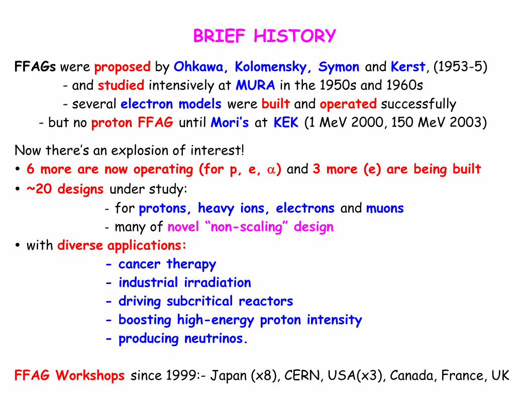
BRIEF HISTORY
FFAGs were proposed by Ohkawa, Kolomensky, Symon and Kerst, (1953-5) - and studied intensively at MURA in the 1950s and 1960s - several electron models were built and operated successfully - but no proton FFAG until Mori’s at KEK (1 MeV 2000, 150 MeV 2003)
Now there’s an explosion of interest! 6 more are now operating (for p, e, α) and 3 more (e) are being built ~20 designs under study:
- for protons, heavy ions, electrons and muons - many of novel “non-scaling” design
with diverse applications: - cancer therapy - industrial irradiation - driving subcritical reactors - boosting high-energy proton intensity - producing neutrinos.
FFAG Workshops since 1999:- Japan (x8), CERN, USA(x3), Canada, France, UK
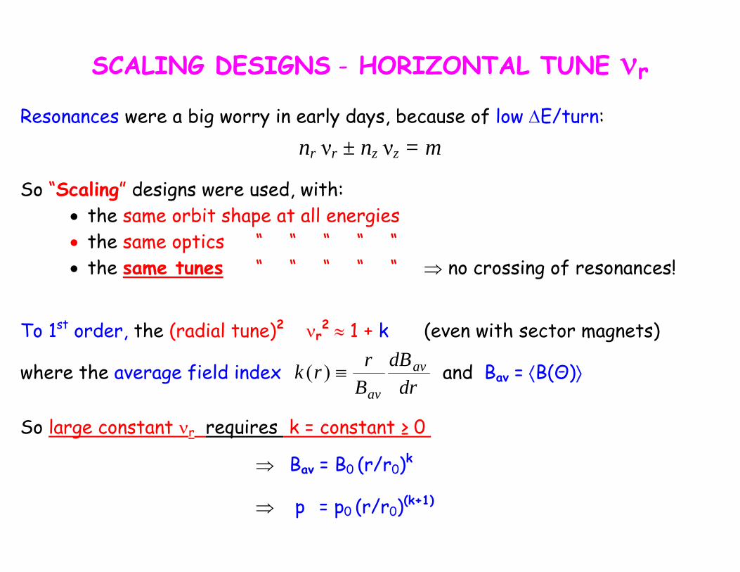
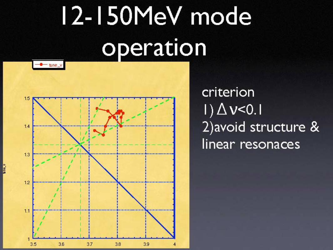
SCALING DESIGNS - HORIZONTAL TUNE νr
Resonances were a big worry in early days, because of low ΔE/turn: nr νr ± nz νz = m
So “Scaling” designs were used, with: • the same orbit shape at all energies • the same optics “ “ “ “ “ • the same tunes “ “ “ “ “ ⇒ no crossing of resonances!
To 1st order, the (radial tune)2 νr
2 ≈ 1 + k (even with sector magnets)
drdB
Brrk av
av≡)(where the average field index and Bav = ⟨B(Θ)⟩
So large constant νr requires k = constant ≥ 0
⇒ Bav = B0 (r/r0)k
⇒ p = p0 (r/r0)(k+1)
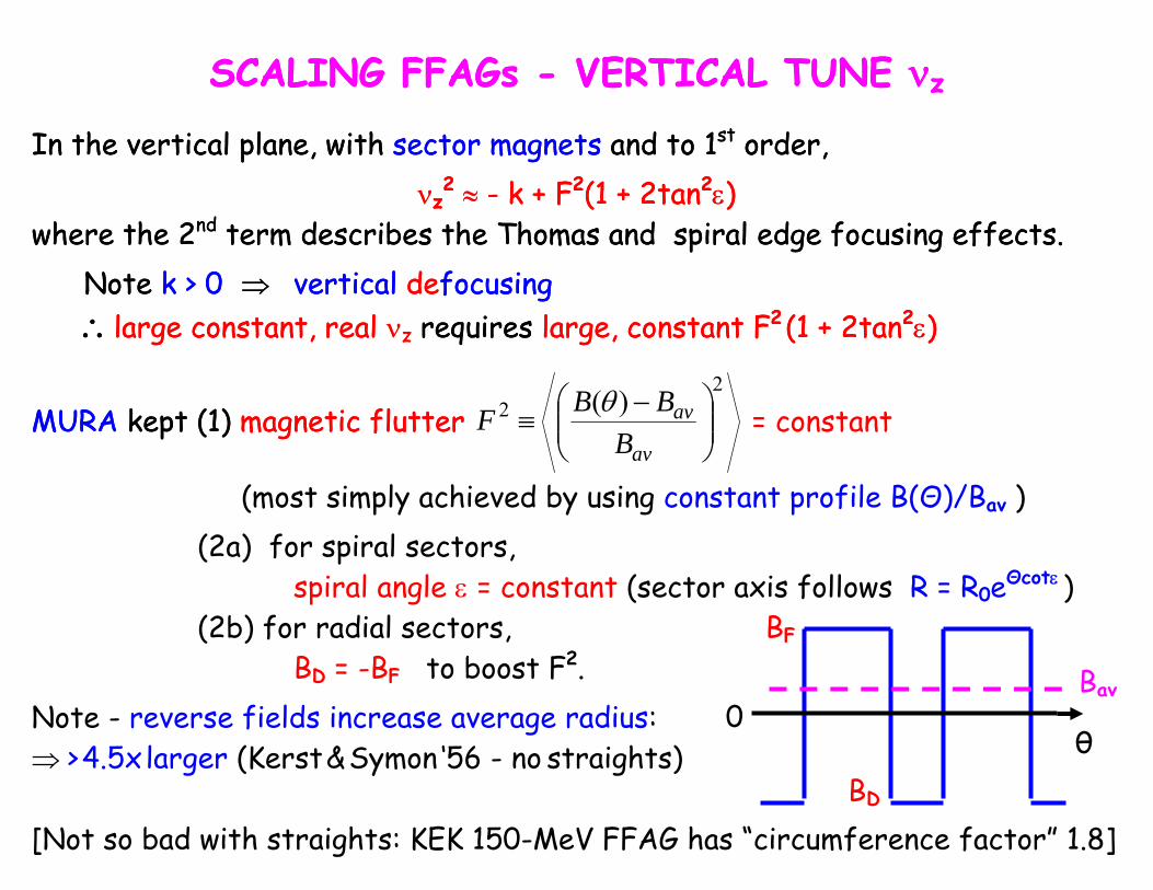
SCALING FFAGs - VERTICAL TUNE νz SCALING FFAGs - VERTICAL TUNE νz
In the vertical plane, with sector magnets and to 1st order, In the vertical plane, with sector magnets and to 1st order, νz
2 ≈ - k + F2(1 + 2tan2ε) νwhere the 2nd term describes the Thomas and spiral edge focusing effects. where the 2
z2 ≈ - k + F2(1 + 2tan2ε)
nd term describes the Thomas and spiral edge focusing effects.
Note k > 0 ⇒ vertical defocusing Note k > 0 ⇒ vertical defocusing ∴large constant, real νz requires large, constant F2
(1 + 2tan2ε) ∴large constant, real νz requires large, constant F2 (1 + 2tan2ε)
2
2 )(⎟⎟⎠
⎞⎜⎜⎝
⎛ −≡
av
av
BBBF θ = constant MURA kept (1) magnetic flutter MURA kept (1) magnetic flutter
(most simply achieved by using constant profile B(Θ)/Bav ) (2a) for spiral sectors,
spiral angle ε = constant (sector axis follows R = R0eΘcotε ) (2b) for radial sectors, BF
BD = -BF to boost F2. Bav0 Note - reverse fields increase average radius:
θ ⇒ > 4.5x larger (Kerst & Symon ‘56 - no straights) BD
[Not so bad with straights: KEK 150-MeV FFAG has “circumference factor” 1.8]
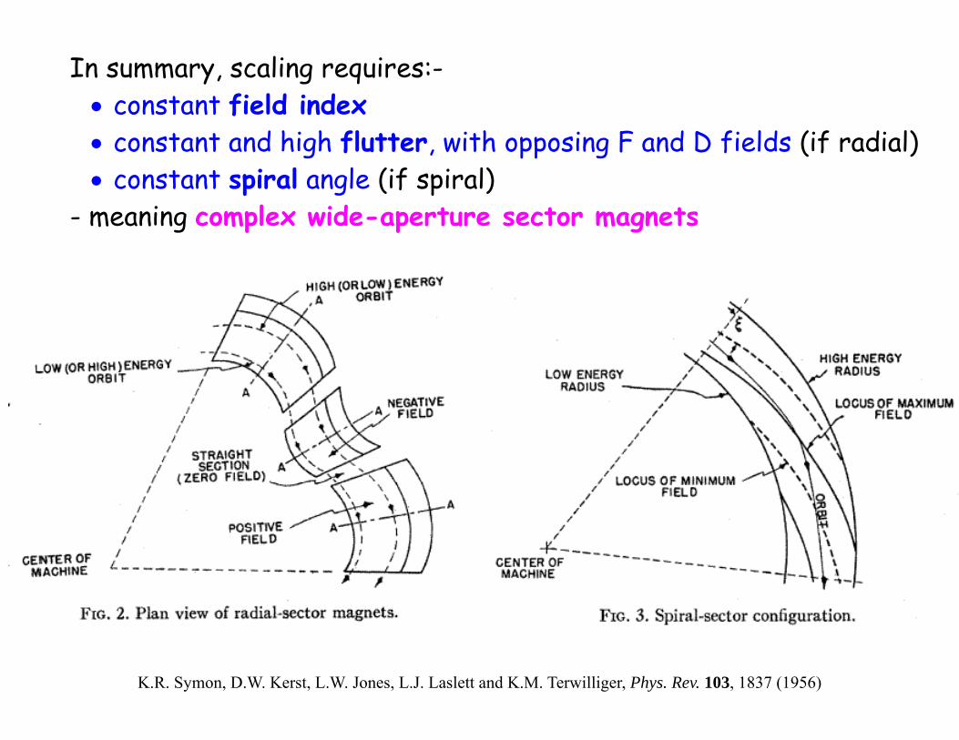
In summary, scaling requires:-
• constant field index • constant and high flutter, with opposing F and D fields (if radial) • constant spiral angle (if spiral)
- meaning complex wide-aperture sector magnets
K.R. Symon, D.W. Kerst, L.W. Jones, L.J. Laslett and K.M. Terwilliger, Phys. Rev. 103, 1837 (1956)
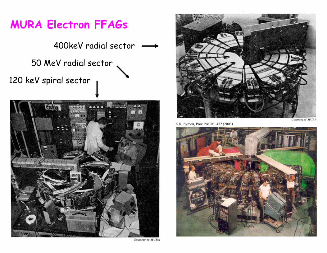
MURA Electron FFAGs
400keV radial sector
50 MeV radial sector
120 keV spiral sector
K.R. Symon, Proc PAC03, 452 (2003)
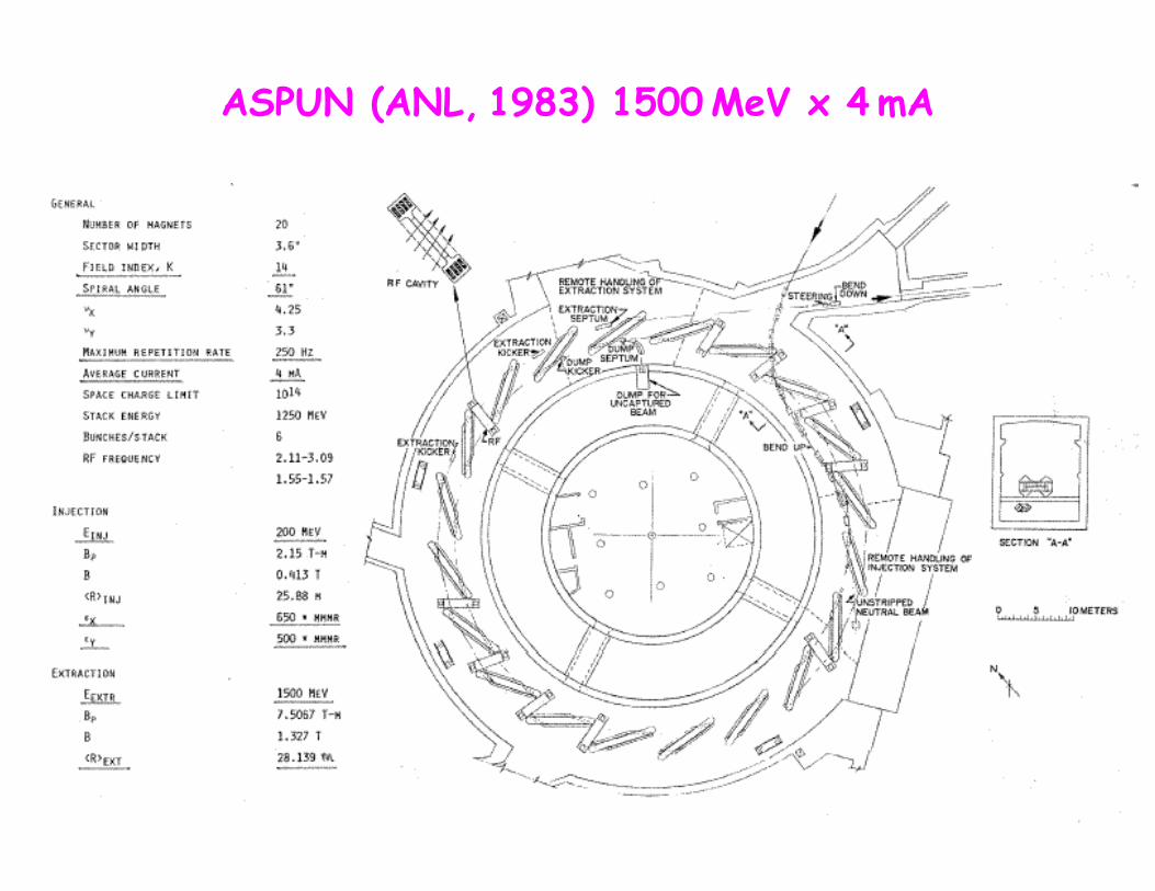
ASPUN (ANL, 1983) 1500 MeV x 4 mA
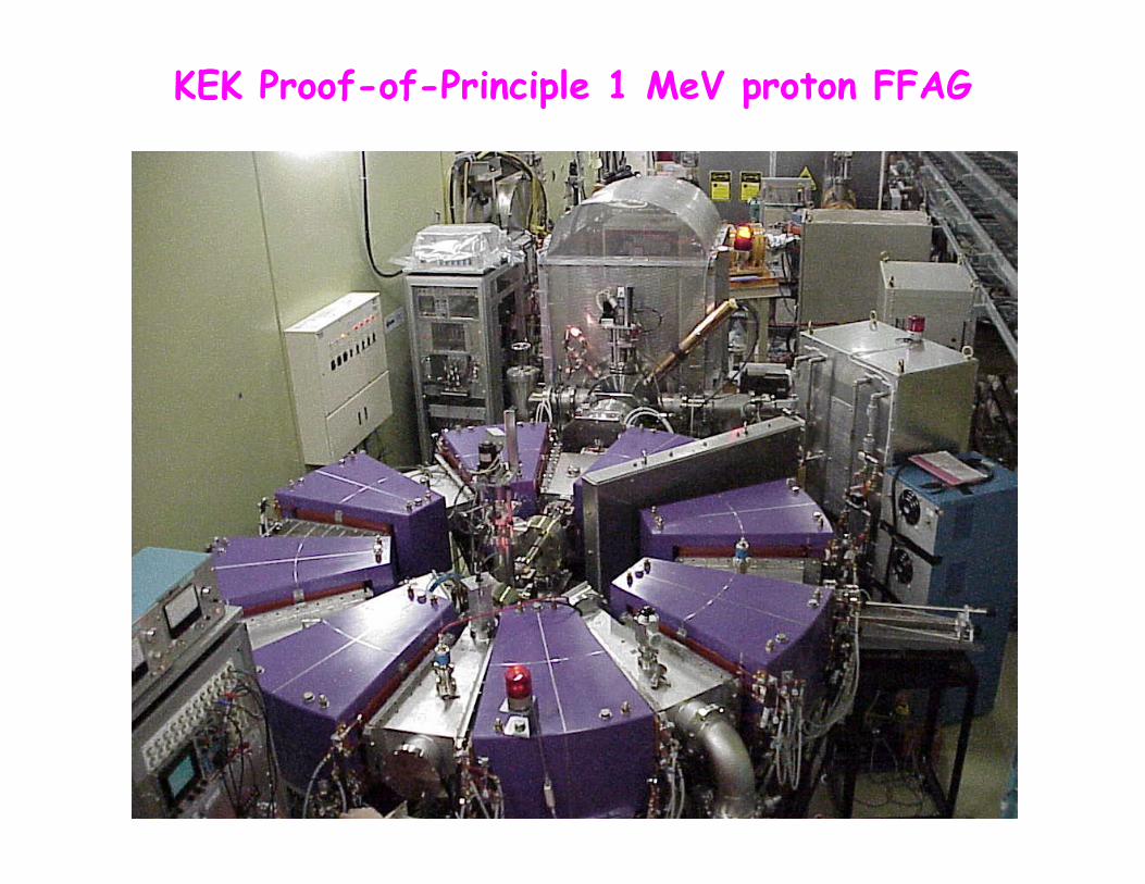
KEK Proof-of-Principle 1 MeV proton FFAG
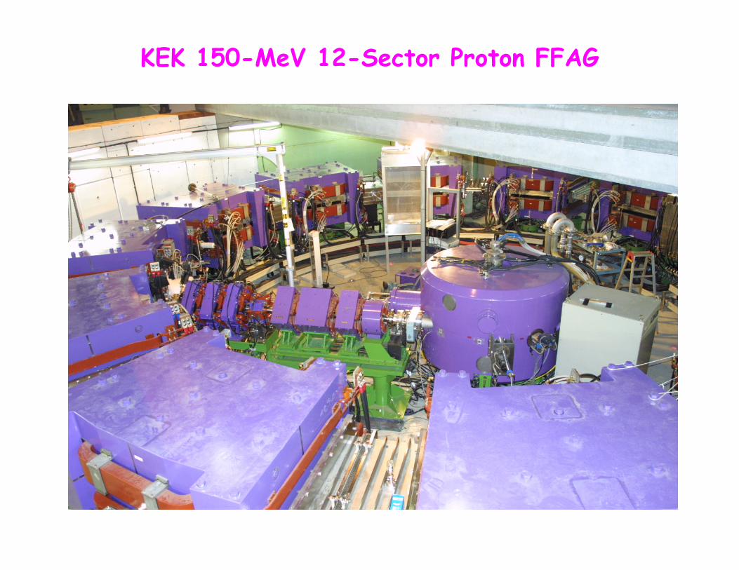
KEK 150-MeV 12-Sector Proton FFAG
INNOVATIONS AT KEK
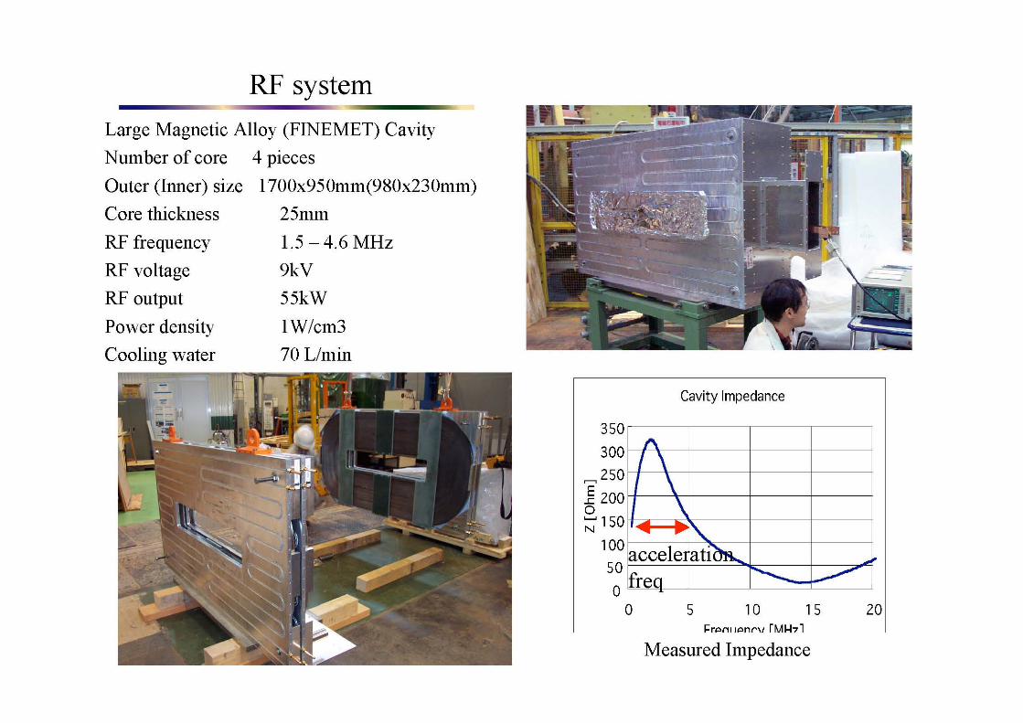
Mori’s 1 MeV (2000) and 150 MeV proton FFAGs introduced two important innovations: 1. FINEMET metallic alloy tuners allowing:
• rf modulation at 250 Hz or more → high beam-pulse rep rates (remember the unreliable rotary capacitors on synchrocyclotrons, which operate in the same mode as FFAGs)
• high permeability → short cavities with high effective fields • low Q (≅1) → broadband operation - no active tuning needed
2. DFD triplet sector magnets:
powered as a single unit Ds acts as the return yokes, automatically providing reverse field modern techniques enable accurate computation of the pole shape for constant field index k
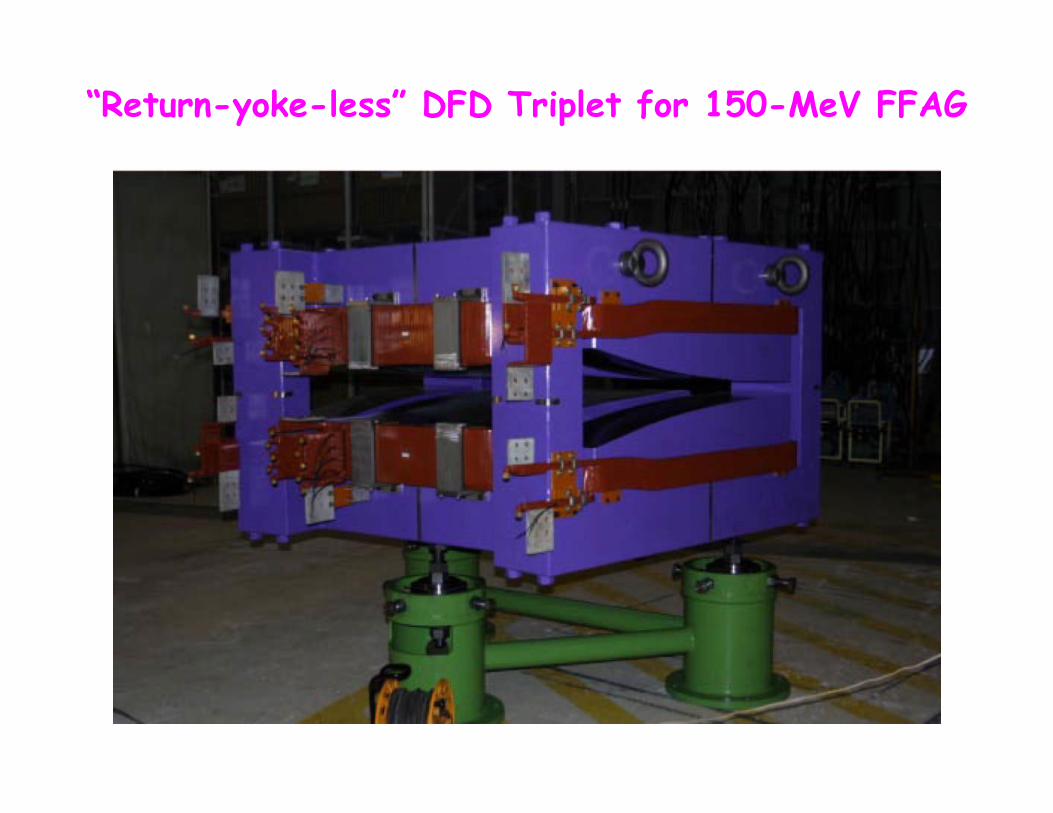
“Return-yoke-less” DFD Triplet for 150-MeV FFAG
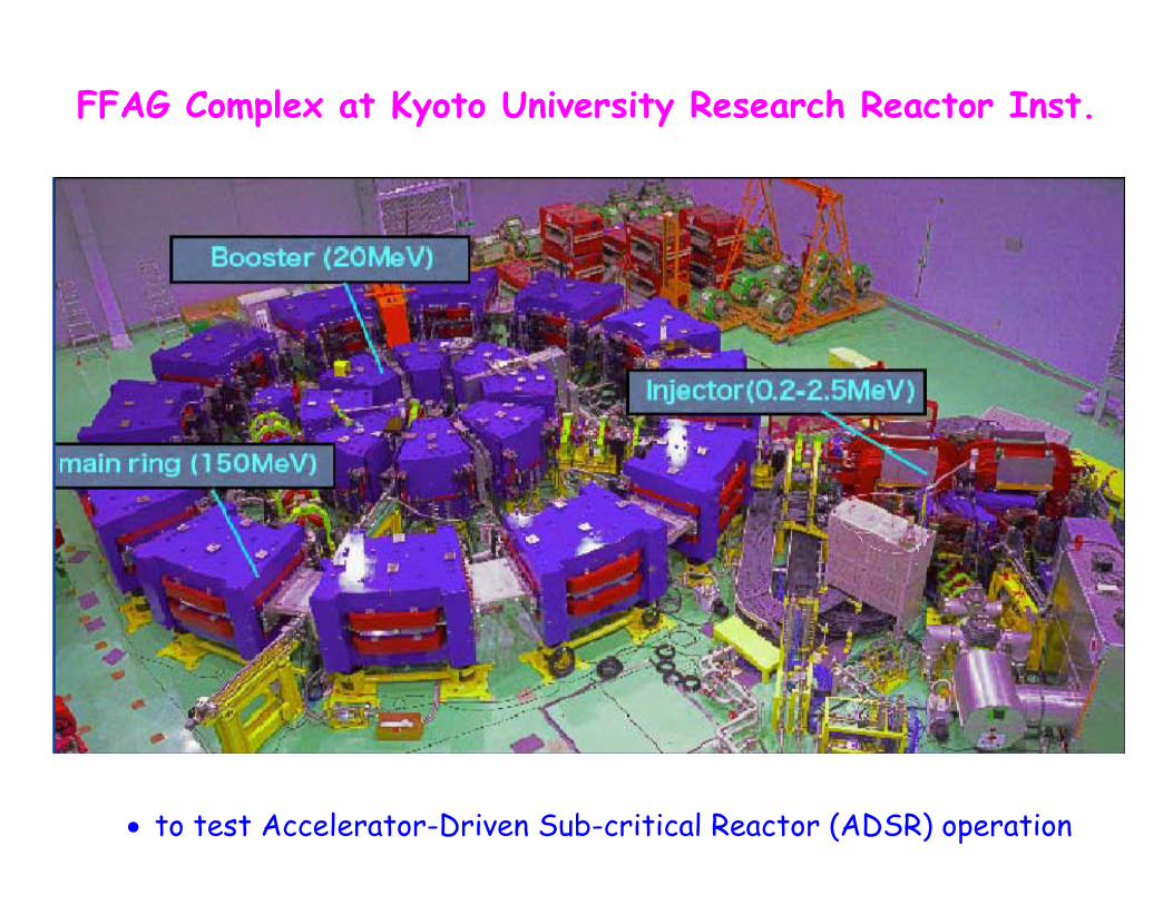
FFAG Complex at Kyoto University Research Reactor Inst.
• to test Accelerator-Driven Sub-critical Reactor (ADSR) operation
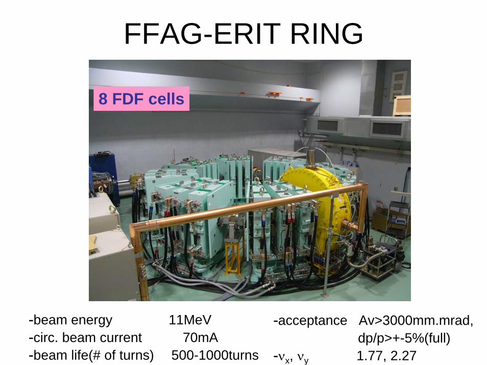
FFAG-ERIT RING
-acceptance Av>3000mm.mrad,dp/p>+-5%(full)
-νx, νy 1.77, 2.27
-beam energy 11MeV-circ. beam current 70mA-beam life(# of turns) 500-1000turns
8 FDF cells
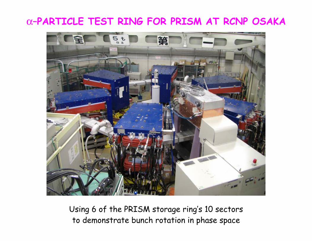
α–PARTICLE TEST RING FOR PRISM AT RCNP OSAKA
Using 6 of the PRISM storage ring’s 10 sectors to demonstrate bunch rotation in phase space
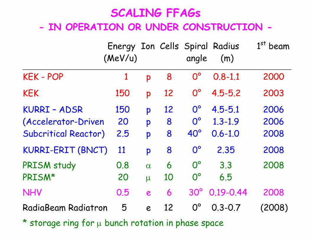
SCALING FFAGs - IN OPERATION OR UNDER CONSTRUCTION -
Energy Ion Cells Spiral Radius 1st beam (MeV/u) angle (m)
KEK - POP 1 p 8 0° 0.8-1.1 2000
KEK 150 p 12 0° 4.5-5.2 2003
KURRI – ADSR 150 p 12 0° 4.5-5.1 2006 (Accelerator-Driven 20 p 8 0° 1.3-1.9 2006 Subcritical Reactor) 2.5 p 8 40° 0.6-1.0 2008
KURRI-ERIT (BNCT) 11 p 8 0° 2.35 2008 PRISM study 0.8 α 6 0° 3.3 2008 PRISM* 20 μ 10 0° 6.5 NHV 0.5 e 6 30° 0.19-0.44 2008 RadiaBeam Radiatron 5 e 12 0° 0.3-0.7 (2008) * storage ring for μ bunch rotation in phase space
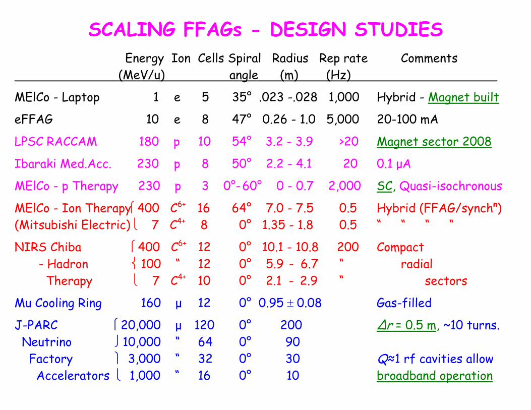
SCALING FFAGs - DESIGN STUDIES
Energy Ion Cells Spiral Radius Rep rate Comments (MeV/u) angle (m) (Hz)
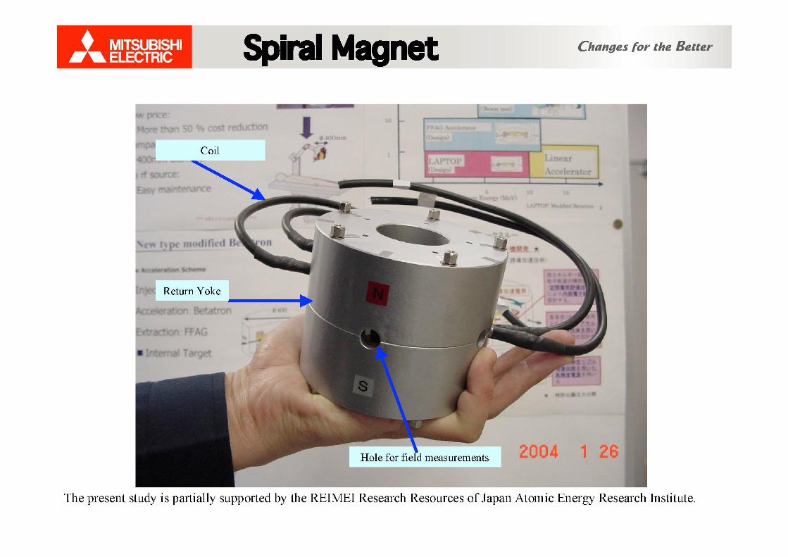
MElCo - Laptop 1 e 5 35° .023 -.028 1,000 Hybrid - Magnet built
eFFAG 10 e 8 47° 0.26 - 1.0 5,000 20-100 mA
LPSC RACCAM 180 p 10 54° 3.2 - 3.9 >20 Magnet sector 2008
Ibaraki Med.Acc. 230 p 8 50° 2.2 - 4.1 20 0.1 μA
MElCo - p Therapy 230 p 3 0°- 60° 0 - 0.7 2,000 SC, Quasi-isochronous
MElCo - Ion Therapy⎧400 C6+ 16 64° 7.0 - 7.5 0.5 Hybrid (FFAG/synchn) (Mitsubishi Electric) ⎩ 7 C4+ 8 0° 1.35 - 1.8 0.5 “ “ “ “
NIRS Chiba ⎧400 C6+ 12 0° 10.1 - 10.8 200 Compact - Hadron ⎨ 100 “ 12 0° 5.9 - 6.7 “ radial
Therapy ⎩ 7 C4+ 10 0° 2.1 - 2.9 “ sectors
Mu Cooling Ring 160 μ 12 0° 0.95 ± 0.08 Gas-filled
J-PARC ⎧20,000 μ 120 0° 200 ∆r = 0.5 m, ~10 turns. Neutrino ⎭ 10,000 “ 64 0° 90 Factory ⎫ 3,000 “ 32 0° 30 Q≈1 rf cavities allow Accelerators ⎩ 1,000 “ 16 0° 10 broadband operation

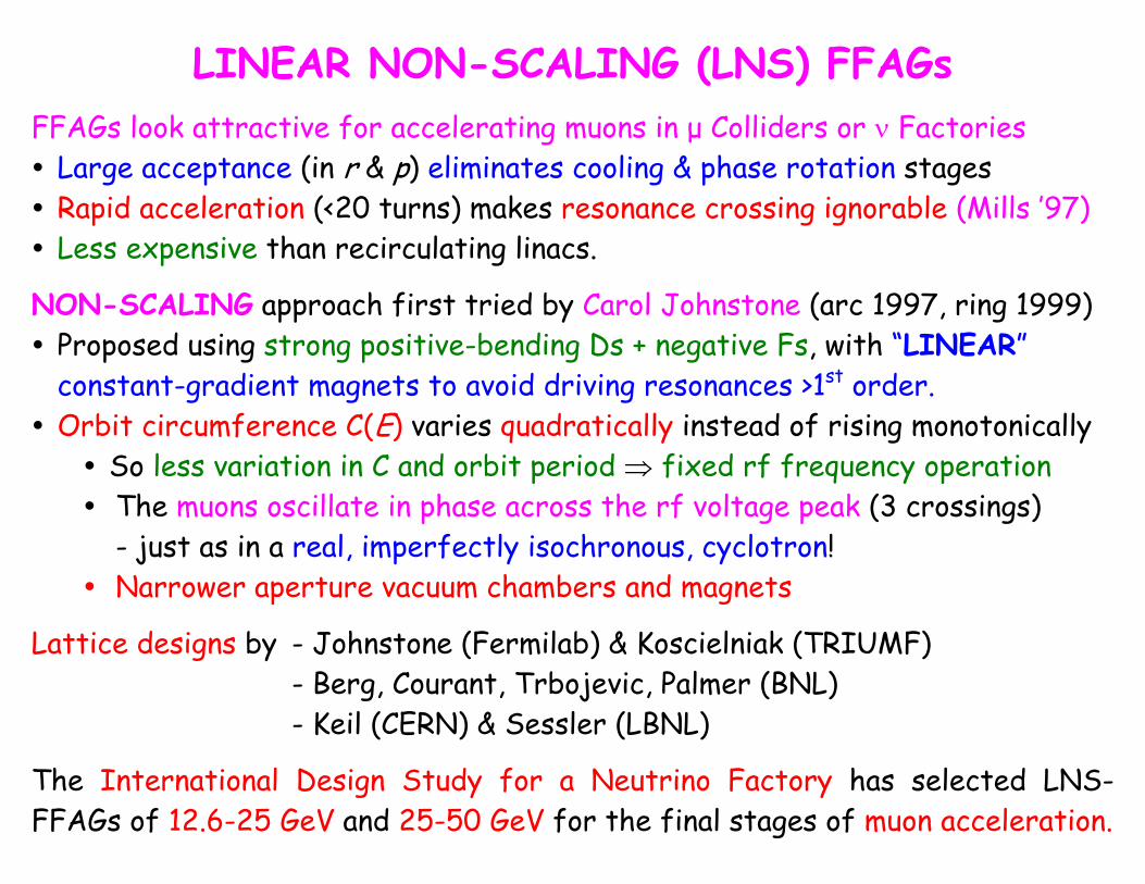
LINEAR NON-SCALING (LNS) FFAGs
FFAGs look attractive for accelerating muons in μ Colliders or ν Factories Large acceptance (in r & p) eliminates cooling & phase rotation stages Rapid acceleration (<20 turns) makes resonance crossing ignorable (Mills ’97) Less expensive than recirculating linacs.
NON-SCALING approach first tried by Carol Johnstone (arc 1997, ring 1999) Proposed using strong positive-bending Ds + negative Fs, with “LINEAR” constant-gradient magnets to avoid driving resonances >1st order.
Orbit circumference C(E) varies quadratically instead of rising monotonically So less variation in C and orbit period ⇒ fixed rf frequency operation The muons oscillate in phase across the rf voltage peak (3 crossings)
- just as in a real, imperfectly isochronous, cyclotron! Narrower aperture vacuum chambers and magnets
Lattice designs by - Johnstone (Fermilab) & Koscielniak (TRIUMF) - Berg, Courant, Trbojevic, Palmer (BNL)
- Keil (CERN) & Sessler (LBNL)
The International Design Study for a Neutrino Factory has selected LNS-FFAGs of 12.6-25 GeV and 25-50 GeV for the final stages of muon acceleration.
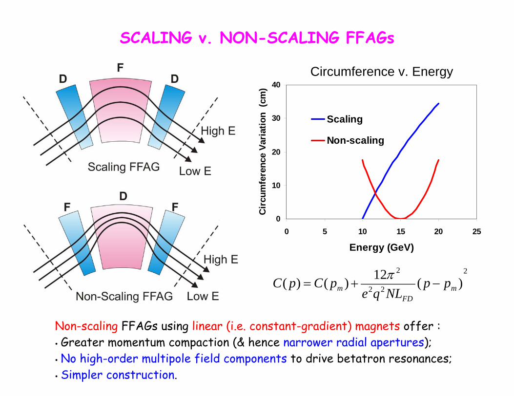
SCALING v. NON-SCALING FFAGs
Circumference v. Energy
0
10
20
30
40
0 5 10 15 20 25
Energy (GeV)C
ircu
mfe
renc
e Va
riat
ion
(cm
)
Scaling
Non-scaling
2
22
2
)(12)()( mFD
m ppNLqe
pCpC −+=π
Non-scaling FFAGs using linear (i.e. constant-gradient) magnets offer : Greater momentum compaction (& hence narrower radial apertures); No high-order multipole field components to drive betatron resonances; Simpler construction.
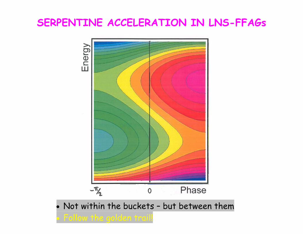
SERPENTINE ACCELERATION IN LNS-FFAGs
• Not within the buckets – but between them • Follow the golden trail!
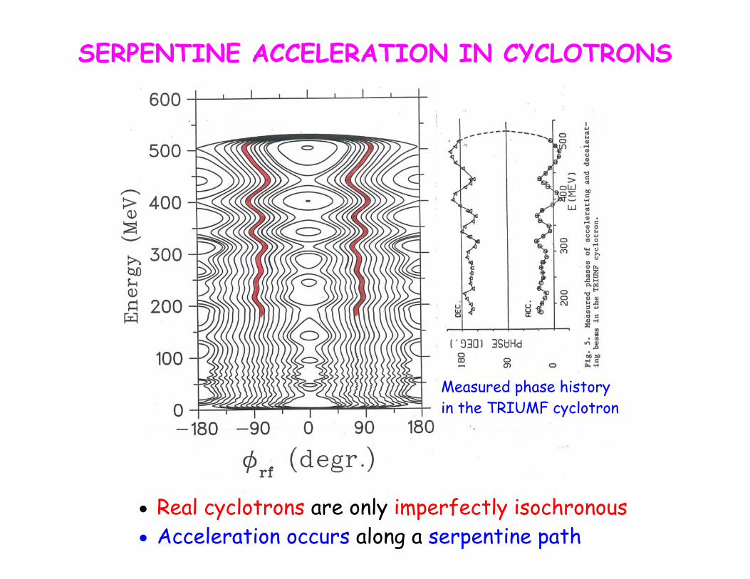
SERPENTINE ACCELERATION IN CYCLOTRONS
Measured phase history in the TRIUMF cyclotron
• Real cyclotrons are only imperfectly isochronous • Acceleration occurs along a serpentine path
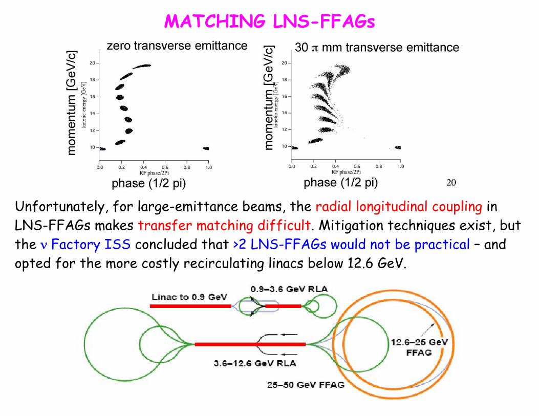
MATCHING LNS-FFAGs Unfortunately, for large-emittance beams, the radial longitudinal coupling in LNS-FFAGs makes transfer matching difficult. Mitigation techniques exist, but the ν Factory ISS concluded that >2 LNS-FFAGs would not be practical – and opted for the more costly recirculating linacs below 12.6 GeV.
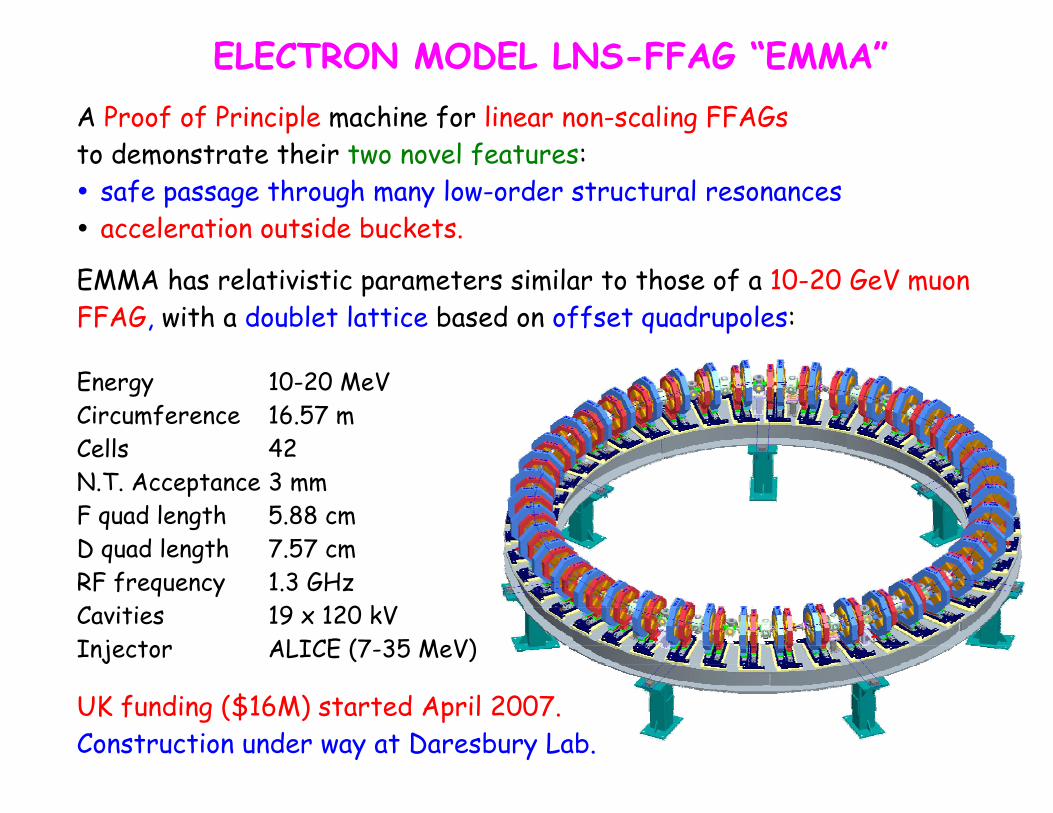
ELECTRON MODEL LNS-FFAG “EMMA”
A Proof of Principle machine for linear non-scaling FFAGs to demonstrate their two novel features: safe passage through many low-order structural resonances acceleration outside buckets.
EMMA has relativistic parameters similar to those of a 10-20 GeV muon FFAG, with a doublet lattice based on offset quadrupoles: Energy 10-20 MeV Circumference 16.57 m Cells 42 N.T. Acceptance 3 mm F quad length 5.88 cm D quad length 7.57 cm RF frequency 1.3 GHz Cavities 19 x 120 kV Injector ALICE (7-35 MeV)
UK funding ($16M) started April 2007.
Construction under way at Daresbury Lab.
EMMA made a major impact at EPAC in Genoa!
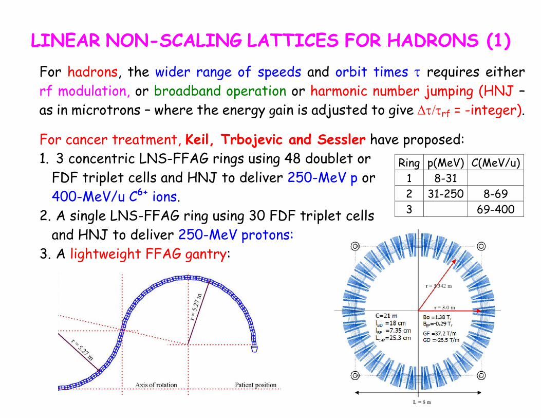
LINEAR NON-SCALING LATTICES FOR HADRONS (1)
For hadrons, the wider range of speeds and orbit times τ requires either rf modulation, or broadband operation or harmonic number jumping (HNJ –as in microtrons – where the energy gain is adjusted to give Δτ/τrf = -integer).
For cancer treatment, Keil, Trbojevic and Sessler have proposed: 1. 3 concentric LNS-FFAG rings using 48 doublet or
FDF triplet cells and HNJ to deliver 250-MeV p or 400-MeV/u C6+ ions.
Ring p(MeV) C(MeV/u) 1 8-31 2 31-250 8-69 3 69-400 2. A single LNS-FFAG ring using 30 FDF triplet cells
and HNJ to deliver 250-MeV protons: 3. A lightweight FFAG gantry:
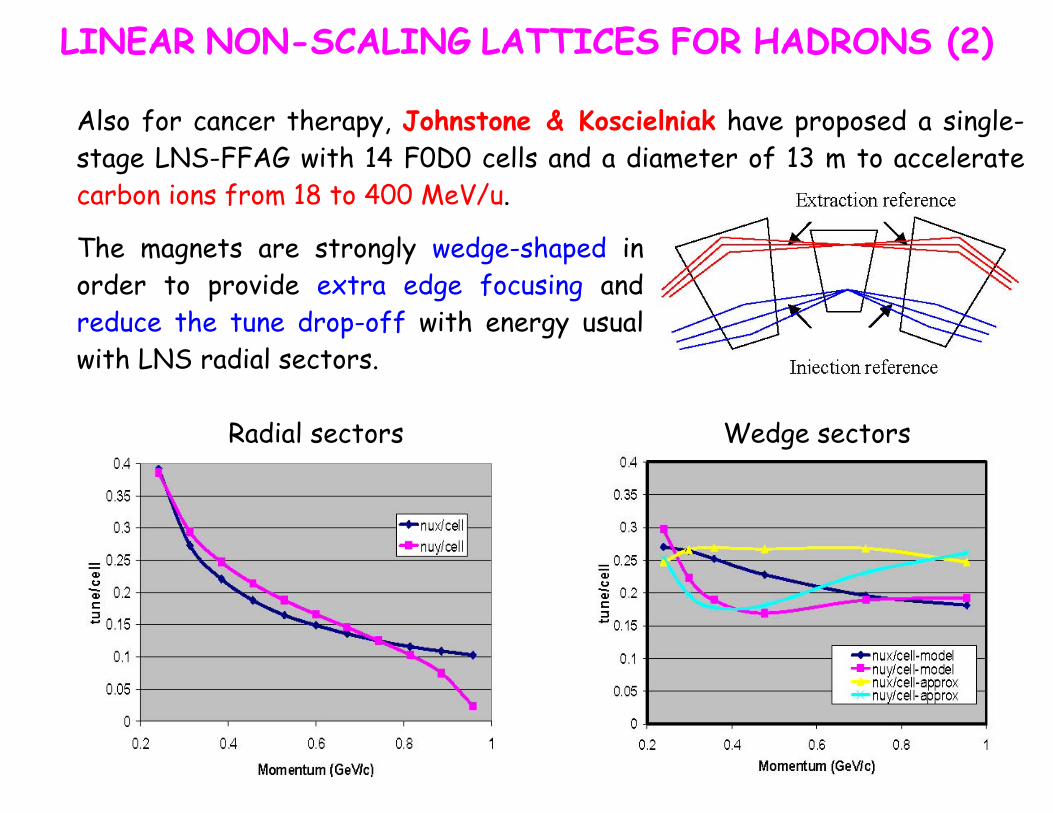
LINEAR NON-SCALING LATTICES FOR HADRONS (2) Also for cancer therapy, Johnstone & Koscielniak have proposed a single-stage LNS-FFAG with 14 F0D0 cells and a diameter of 13 m to accelerate carbon ions from 18 to 400 MeV/u.
The magnets are strongly wedge-shaped in order to provide extra edge focusing and reduce the tune drop-off with energy usual with LNS radial sectors. Radial sectors Wedge sectors
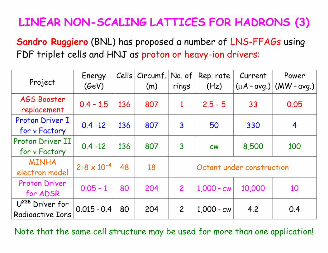
LINEAR NON-SCALING LATTICES FOR HADRONS (3)
Sandro Ruggiero (BNL) has proposed a number of LNS-FFAGs using FDF triplet cells and HNJ as proton or heavy-ion drivers:
Project Energy (GeV)
Cells Circumf. (m)
No. of rings
Rep. rate (Hz)
Current (μA – avg.)
Power (MW – avg.)
AGS Booster replacement 0.4 – 1.5 136 807 1 2.5 - 5 33 0.05
Proton Driver I for ν Factory 0.4 -12 136 807 3 50 330 4
Proton Driver II for ν Factory 0.4 -12 136 807 3 cw 8,500 100
MINHA electron model 2-8 x 10⁻⁴ 48 18 Octant under construction
Proton Driver for ADSR 0.05 – 1 80 204 2 1,000 – cw 10,000 10
U238 Driver for Radioactive Ions 0.015 - 0.4 80 204 2 1,000 - cw 4.2 0.4
Note that the same cell structure may be used for more than one application!
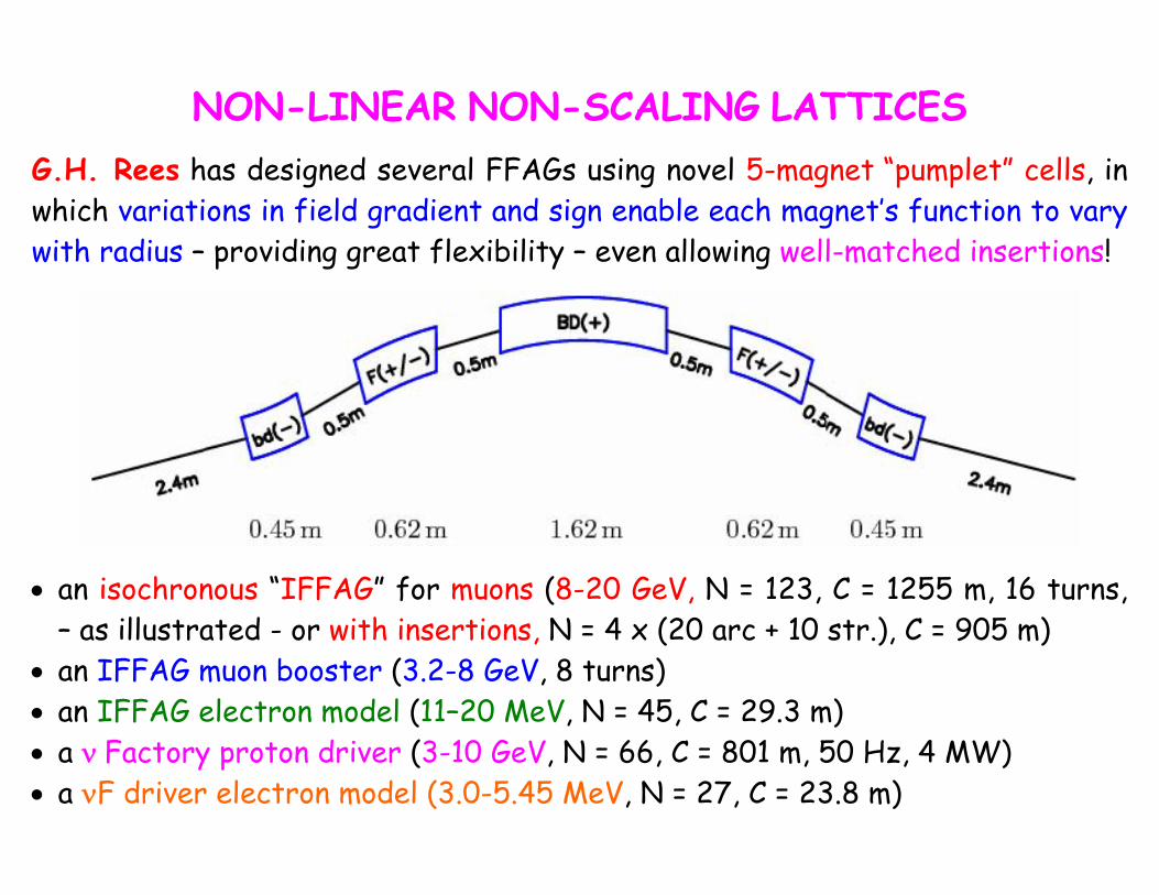
NON-LINEAR NON-SCALING LATTICES
G.H. Rees has designed several FFAGs using novel 5-magnet “pumplet” cells, in which variations in field gradient and sign enable each magnet’s function to vary with radius – providing great flexibility – even allowing well-matched insertions!
• an isochronous “IFFAG” for muons (8-20 GeV, N = 123, C = 1255 m, 16 turns, – as illustrated - or with insertions, N = 4 x (20 arc + 10 str.), C = 905 m)
• an IFFAG muon booster (3.2-8 GeV, 8 turns) • an IFFAG electron model (11–20 MeV, N = 45, C = 29.3 m) • a ν Factory proton driver (3-10 GeV, N = 66, C = 801 m, 50 Hz, 4 MW) • a νF driver electron model (3.0-5.45 MeV, N = 27, C = 23.8 m)
SUMMARY
Last 10 years have seen rebirth of interest in FFAGs world-wide
8 built, 3 under way, ~20 designs proposed
Interest stems from applications needing the FFAG’s unique characteristics:
- high rep rate - high acceptance
A whole new class of “non-scaling” FFAGs has been discovered
- several varieties are being studied - perhaps scope for more?


