Introduction to Fluid Machines and Compressible Flow Prof. S.K Som Department of Mechanical Engineering Indian Institute of Technology, Kharagpur Lecture No. # 24 Axial Flow Compressor Part I Good morning and welcome you all to this session of the course. Today, we will be discussing the axial flow compressor, last class we have more or less completed a brief discussion on this centrifugal compressors and now, we will be discussing axial flow compressor. The basic principle is mostly the same as that of a centrifugal compressor, what is the basic principle that by observing the mechanical energy from outside the working fluid, which is usually air gains its static pressure that is the basic purpose of a compressor whether it is a centrifugal or an axial flow compressor. An axial flow compressor like a centrifugal compressor also consists of a router and a stator. Router is the rotating part of the compressor, where the mechanical energy is being supplied and its consist of a number of blades, which rotates and the mechanical energy is supplied in the form of an external torque under which there is a rotational motion of the rotating blades there are the blades, which rotate. And the air acquires the energy and ultimately what happens its velocity and static pressure is increased and the stator part of the compressor, which is known as diffuser, the function of which is that here we gain the static pressure from the velocity of the air by allowing the air to have a decelerating flow in this passage it is known as diffusion process, the diffusion takes place, where we get more static pressure by virtue of the or of the expense of kinetic energy and finally at the outlet we get air at high pressure but at low velocity. So, the basic principle is same but the major difference between the axial and the centrifugal compressor is that the flow takes place in the axial direction, where as in the centrifugal compressor we have seen that flow takes place in the radially outward direction. So, the inlet and outlet of the flow whereas in the radial location and whereas in
Transcript
Introduction to Fluid Machines and Compressible Flow
Prof. S.K Som
Department of Mechanical Engineering
Indian Institute of Technology, Kharagpur
Lecture No. # 24
Axial Flow Compressor Part I
Good morning and welcome you all to this session of the course. Today, we will be
discussing the axial flow compressor, last class we have more or less completed a brief
discussion on this centrifugal compressors and now, we will be discussing axial flow
compressor. The basic principle is mostly the same as that of a centrifugal compressor,
what is the basic principle that by observing the mechanical energy from outside the
working fluid, which is usually air gains its static pressure that is the basic purpose of a
compressor whether it is a centrifugal or an axial flow compressor.
An axial flow compressor like a centrifugal compressor also consists of a router and a
stator. Router is the rotating part of the compressor, where the mechanical energy is being
supplied and its consist of a number of blades, which rotates and the mechanical energy is
supplied in the form of an external torque under which there is a rotational motion of the
rotating blades there are the blades, which rotate.
And the air acquires the energy and ultimately what happens its velocity and static
pressure is increased and the stator part of the compressor, which is known as diffuser, the
function of which is that here we gain the static pressure from the velocity of the air by
allowing the air to have a decelerating flow in this passage it is known as diffusion
process, the diffusion takes place, where we get more static pressure by virtue of the or of
the expense of kinetic energy and finally at the outlet we get air at high pressure but at low
velocity.
So, the basic principle is same but the major difference between the axial and the
centrifugal compressor is that the flow takes place in the axial direction, where as in the
centrifugal compressor we have seen that flow takes place in the radially outward
direction. So, the inlet and outlet of the flow whereas in the radial location and whereas in
the peripherals speed of the router, but here what happens the flow takes place in the axial
direction. So, therefore, the inlet and outlet of the flow takes place at a particular radial
location and all such radial locations the flow inlet is there and flow outlet is there that
will be explained when I will explain through the diagram.
So, the major difference is the entire flow takes place in the axial direction and there are
different number of stages, each stage consists of a router blade the router and a stator
consisting of stator blades and this way a stage is considered that a router and stator and
number of stages are there. This is the overall structure of an axial flow compressor that
differs from a centrifugal flow compressor, which is a radially outward flow type it is an
axial flow type through number of stages. At the same time you should know that these
axial flow compressor the advantage your centrifugal compressor is that it can handle a
large amount of at the flow rate is more as compared to the centrifugal compressor it can
run more efficiently with high flow.
(Refer Slide Time: 03:49)
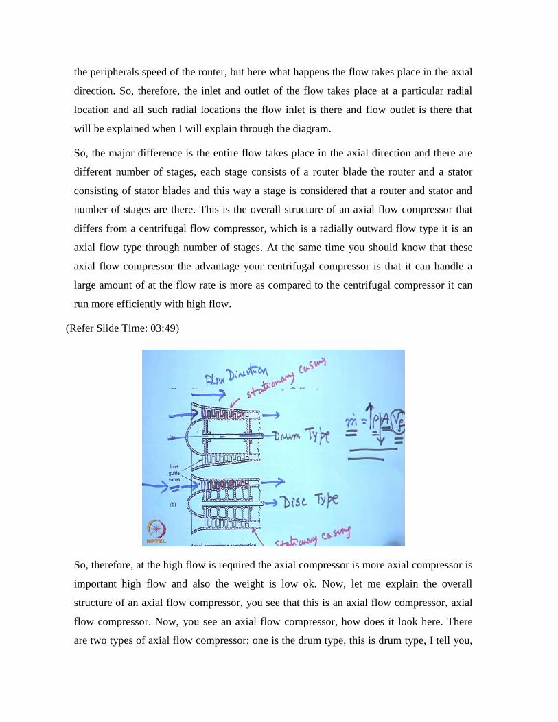
So, therefore, at the high flow is required the axial compressor is more axial compressor is
important high flow and also the weight is low ok. Now, let me explain the overall
structure of an axial flow compressor, you see that this is an axial flow compressor, axial
flow compressor. Now, you see an axial flow compressor, how does it look here. There
are two types of axial flow compressor; one is the drum type, this is drum type, I tell you,
drum type, what is the difference I tell you, this is the disc type. Now, basic structure
consists like that there is either a drum rotating drum this is the shaft or a disc on which
this router blades are being mounted this is the router blades and these router blades this is
the drum type is mounted on the rotating drum and with the rotation of the drum. For disc,
in a disc type this is the router blades, this is the router blade so router blades rotate, so
these router blades and number of blades are there along the periphery of the drum. So, at
any axial location you see there are a number of blades, if you see this view front view,
you see one blade there are number of blades in the periphery, which had being attached to
either drum or disc known as disc type.
And there is a stationary casing this is the stationary casing I write, this is the stationary
casing, here also this is the stationary casing and these stator blades are screwed or
attached to this stationary casing these are the stator blades. And one router and one stator,
one router and one stator comprises one stage so, here also the stator blades are fixed to
the casing. And there is a inlet row of guide, when upstream of the first router this is
actually not this is stator this is also a stator static part attached to that and these are
known as inlet guide vanes, which first direct the air properly in the axial direction.
So, this is the flow, flow direction, this is the air flow like that, flow direction so this is the
flow direction and this is the direction of the axis, this is the direction of the axis, the flow
takes place in the axial direction. First it comes to the inlet guide vanes then through router
and stator then router and stator a number of router blades number of stator blades and
number of router blades number of stator blades and a combination of router and stator
comprises the stage. This is an overall view of the axial flow compressor the air enters in
this way; the air enters in this way, so therefore air flows through this annulus area formed
by the blade passages. So, this is an overall ah diagram of an axial flow compressor air
goes out.
So, axial flow compressors there are other things that I will tell you that while designing
this annulus area it is made a convergent type that means the annulus area goes on
decreasing in that direction of the flow, why? This is because, you know from continuity
mass flow rate is written as mass flow rate can be written as rho times the flow area times
the velocity of flow if here. And this we will consider an average flow velocity over a
cross section and this is the annulus area the cross section the area provided to the flow
and this is the average density at that section. Now, as the flow takes place here by the
action of the router and stator the pressure increases this is the increasing direction of the
pressure so density increases. So, for a given mass flow rate, because at steady state from
continuity the mass flow rate will be same throughout the machine so, if you want to make
the axial flow velocity constant we have to decrease the cross sectional area.
And the main motto is to make the axial flow velocity constant despite the increase of rho
for which we have to decrease the annulus flow area same for drum type or a disc type.
This is one of the major considerations in the geometrical design of the compressors, the
blade hide and other things are will come after wards, but this is one of the main
considerations. So, this gives you a overall picture of an axial flow compressor, how does
it look like, what is the basic direction of flow the flow takes place in the axial direction.
Now, if we see the number of vanes now, before that we consider now, if you see from the
top view then we will see a particular rho is like this including the guide vane, its look like
this, you see.
(Refer Slide Time: 09:02)
When you would look from the top ok, over the periphery then you will see that this is the
direction that is these are the router, this is the router vane, this is the diffuser and this is
the inlet guide vanes. Rather I think you can, yes, see this way, this will be the way
actually yes. So, therefore this at the number of blades that you can see or better you see
this way know this way it is better. So, that these goes from these in this direction why
they have made a flow direction like that I do not understand this direction will be here, I
think the flow this is a peripheral direction the numbers of blades are there so this will go
like this and will come like this, I think this is the direction, not this is the direction.
So, the flow takes place like that there are inlet guide vanes, which directs the flow in such
a way ultimately it goes through the router series of router blades and the diffuser this is
the diffuser where the velocity is decelerated and the pressure is increased. If you see this
diagram you see that pressure in the inlet guide vanes decreases slightly, because of the
skin friction, because the inlet vanes there is no energy interactions be the static vane so
pressure lot takes place, because of the friction. Then in the router the energy interaction
takes place it moves so therefore router imparts mechanical energy to the fluid by virtue of
which its pressure its velocity and similarly, if you see the velocity, velocity should
remain almost constant, but these inlet guide vanes cross sectional area is slightly
converging type so that the velocity slightly increases.
So, this is the velocity part, I just doing it by rate velocity then what happens by virtue of
these mechanical energy given to it the both velocity and pressure increases this is the
increase in the velocity, this is an increase in the velocity in the router, because it gains
energy there and this is the increase in the pressure. And this is the static pressure, the
increase in static pressure takes place, because there is an divergence in the area this flow
passage area is made in such a way there is an increase in the static pressure, while it
flows through that this is being reflected or manifested by a change in the relative velocity
that I will tell after wards. Then it comes to a series of stator blades known as diffuser
what happens in the diffuser? We get a rise in pressure that is known as difficult diffusion
process in respect to this deceleration of flow that means the flow velocity is reduced.
So, this is a typical pressure velocity diagram, this is the pressure, this is the velocity
diagram, while flowing through the router and diffuser blades and upstream this you
consider the first row of router blade so the upstream of that there are inlet guide vanes ok.
Now, if you consider you come to again this diagram that flow takes place at all radial
locations now, if we consider the flow velocity V f is uniform over all radial locations and
if we consider the flow at any mean height that means, at a mean height of the blade that a
mean radius from the center, yet the flow is basically two dimensional, the flow has got an
axial component and a tangential component, the radial component is relatively less. So, if
the radial component is less, we can consider that two in a components of flow, mainly in
the axial another is the tangential, which is perpendicular to this plane of the figure ok.
And at the same time, if you consider the weight at any cross section along the blade
height ok, at different radial location, if you measure from the central line is constant that
means, the uniform velocity distribution, which is also constant in the axial direction for
which the annulus area is reduced that is different, but radially if we consider it is uniform
and two component of velocity then it is almost a two dimensional. So, this is a two
dimensional representation of a three dimensional flow.
(Refer Slide Time: 13:38)
So, with this representation now, you can have a look of the velocity triangle. Now, if you
see that the same thing that we already shown that the a blade passage formed by the
router and the stator you see these router and the stator that means, this part if we draw
like this that means, if we see from the top this side know oh, oh sorry, sorry, now, it is ok,
now it is, if we see from the top the two routers earlier things were visible know ok. So,
two router blades and two stator blades just a representative figure, I show you this is what
a representative blade passage found by two router blades and two stator blades of a stage.
Now, this is a stage now, what happens? The stage at the inlet to the stage the air comes
with some velocity V 1 with an angle alpha 1, which is nothing but the velocity coming
out of the stator of the previous stage with some angle alpha 1 and this angle is made in
the axial direction, this is the axial direction you understand this is the axial direction. So,
this is the well axial direction ok.
Now, what happens? The router blade shape is like that and if you see the velocity triangle
you see the velocity triangle is that here we can write that V r 1 is the relative velocity as
you know that is V 1 minus oh, not visible that will be a problem with this thing, they
have not this is not actually made in this proper way V r 1 is V 1 minus u. Now, another
difference is this from the centrifugal compressor here the, if you see this again that the
flow takes place axially, if we this diagram is drawn at a section taken at the mean radius
mean height of the blade. So, therefore here what happens the inlet and outlet takes place
at the same radial, we can take it at different radial locations. So, therefore when we see
the picture from the top, we see that the inlet and outlet of the air flow takes place at a
given radius. So, the peripheral speed of the router is same depending upon the radius at
that point.
So, therefore u remains the same, you see the inlet velocity triangle is like that, this is the
absolute velocity with which the air strikes the router blade with an angle alpha 1 with the
axial direction. Then if you make the vector diagram, vector triangle diagram that velocity
triangle then this is your V r 1, this is the V r 1 I, think you can see this is V 1, this is V r 1
and this is the u and this is the V w 1 this part, this is the willing component or tangential
component of velocity V 1 this is your velocity triangle. And this velocity, because of
smooth flow without incident loss this beta 1 should glide that means, should match the
angle of the blade at the inlet and this is the beta, so, beta 1 is the relative velocity angle,
which is the angle of the blade at the inlet.
Similarly, if you see the outlet diagram, the outlet is made like this. So that the flow area
increases in the direction of flow, this is the flow direction ok. So, this is the flow velocity
V f 1, so at the inlet. Now, at the outlet, if you see the velocity diagram this is the relative
velocity V r 2, this is V 2, this is the same u and this is V w 2 ok, this is alpha 2 and beta
2. Now, beta 2 is less than beta 1, this beta 2 is less than beta 1 fluid is directed more
towards axial direction this happens, because of the camber of the blade in a way that the
annulus area increases ok. The annulus area that means these area sorry increases sorry
decreases no sorry, annulus area increases, because of this increase in the velocity V r 2.
So, what happens here you see that V 1 and V 2 that another important thing is that V r 2
then V 2, v 2 is more than V 1, V 2 has to be more then V 1, because in router the fluid
gains the energy, but V r 2, V r 2 is less than V r 1 why? This is because there is an
increase in static pressure, if V r 2 has to be less than V r 1 so this area has to be more. So,
make the annulus area more the camber of the blade has to such that beta 2 is less than
beta 1, these are the important considerations of this velocity triangle.
Now, when it comes to the stator blades then what happens, this is the absolute velocity V
2 we take it comes makes an angle alpha 2 in the axial direction so stator blade does not
move so there is no velocity triangle simply the velocity direction is change as per as the
camber of the stator blade of the curvature of the stator blade. Here also the stator blade
velocity is changed in such a way that alpha 3 is reduced from alpha 2 it is directed more
towards axial direction and the design is made such way that alpha 3 becomes again
equals to alpha 1 so that it can smoothly glide or enter to the router blade of the next stage
so, we make this alpha 3 is equal to alpha 1 these are the important considerations. So, this
show you can draw the velocity triangle at inlet and the velocity triangle at outlet of the
router blades and this is the velocity how does it change in the stator blade ok. Now, we
can write certain formula from this, but problem is that this cannot be shown here at the
same diagram ok.
Let me adjust it, if you can see that thing this is the state now, if you can say, if you can
see now, this blades you may not you may this cut so that you can hold it here. So, now, it
will see this triangle what we can write from this now V f 1 as I have told in the design is
made V f 2 and V f that means, this axial flow velocity. Now, from the geometry of this
tan alpha 1 is what this base divided by V f 1 tan beta 1 is this base divided by V f 1. So, if
you add this two things then we get tan alpha 1 plus tan beta 1 is equal to this plus this is
the u, u by V f because V f 1 is V f 2 is V f, so this is I am writing V f.
Similarly, from the outlet velocity triangle tan alpha 2, if you make the tan alpha 2 from
the simple geometry tan beta 2 is equal to u by V f ok, u by V f. Now, if you equal make
this two equal then you can write tan alpha 1 plus tan beta 1 is equal to tan alpha 2 plus tan
alpha 2 plus ok, tan alpha 2 plus tan beta 2 ok, that we can write or we can write tan alpha
1 minus tan alpha 2 is equal to tan beta 2 minus tan beta 1, this is one very important
relationship, this two this relationship and the geometrical relationship, this two
relationship we can get from the two velocity triangles ok. Now, if we come to the work
here itself I can write now, work if you write here now, work per unit mass W by m work
per unit mass is nothing but what is work per unit mass we know from the Eulers equation
that V w 2 u 2 that is V w 1 u 1 alright, here u 2 is u 1 and that is equal to u. So, therefore
it becomes equal to V w 2 minus V w 1 into u, why? Because u 1 is equal to u 2 is equal to
u ok.
(Refer Slide Time: 23:09)
Now, we see that, if this is true then we can write W is equal to what is V w 1 minus V w
2, let me see again now, V w 1 minus V w 2 is, what is V w 1 minus V w 2 from this
diagram? Now, V w 1 can be written as the this one V w 1, V f 1 tan alpha 1 similarly, V
w 2 is V f 2 tan alpha 2, V f 1, V f 2 is V f. So, therefore this equals to V f tan alpha 1 V w
1 and V w 2 V f tan alpha 2. So, if you follow this velocity triangle then you can write this
is equal to u V f into V w 2 that is tan alpha 2 will come first minus tan alpha 1 again from
the equality as I am done already that tan alpha 2 minus tan alpha 1 is tan beta 1 minus
beta 2, so we can write u V f tan of beta 1 minus tan of beta 2 ok, where from because, we
had this thing earlier shown that, that earlier we shown this thing that actually this is a
problem here this is tan alpha 2 tan alpha 1 minus tan alpha 2 is tan beta 2 minus tan beta
1 ok.
So, therefore tan beta 1 minus tan beta 2 tan other this is the work done per unit mass
sorry, or energy added per unit mass whatever you can write it is your concept energy
here. Now, if you consider that the change in the stagnation temperature, which we called
it a total temperature, I give the normal temperature delta t that means change in the
stagnation temperature of the compressor total change in that C p is the total energy added
to the air of the working in fluid per unit mass that we will equate this one V f tan alpha 2
minus tan alpha 1, I can write tan beta 1 minus beta 2 tan does not matter either of these
two I can write they two are equal. So, therefore the increase in the stagnation temperature
is given by this formula, which is very important that increase in the tan alpha 2 minus tan
alpha 1 divided by C p. Now, what happens is that, the actual stagnation temperature rise
is less than this and this is taken care of by a coefficient lambda first of all let me write
that, which is less than lambda, this is lambda less than 1, lambda less than 1 by this co
efficient lambda, which is known as the work done factor this is the lambda, which is
known as the work done factor, lambda is work done factor.
Now, this is mathematical what is the physical meaning of that and this lambda equals to
one that means that the theoretically the energy per unit mass or work done per unit mass,
which you calculated is not actually important to the liquid sorry, to the fluid to the air
here a less amount is being imparted, because of this lambda factor, which is less than 1,
which is known as work done factor this is because of the fact that we assumed at the
beginning this axial flow is uniform over the entire blade height this is not so and that
creates a problem.
(Refer Slide Time: 27:23)
Now, let us see that thing that, if we consider the this way, if we consider the axial
velocity that is V f and if we consider this is the radial direction, this is the radial direction
r and if we consider this as the blade height, router blade height this is the blade height,
this is the height of router blade, height of router blade. Let us consider the first stage, now
according to our two dimensional assumptions, we have considered that the this is the
dotted line I am showing this is the axial velocity distribution, this is the axial velocity
distribution over the blade height, this is the blade height here I cannot write, because this
space is not there, so here it could have written the alternate is the height of the that is the
radial direction and this is the height of the router blade, I just make a hatch like that for
your understanding.
So, uniform distribution, but what happens in practice, because of the three dimensional
effect the velocity distribution is not uniform, the flow velocity distribution this is the
axial flow velocity V f so, distribution become like this some peak be at the center and
then again it reduces. So, this becomes the distribution of the axial velocity actual
distribution becomes like that instead of this uniform one.
And if you go to further stage for example allow for example a fourth stage number of
stages at there are fifth stage some represented blade height also will change as you go on
that there is a decrease in the area however I show you with the same height fourth stage
for your understanding. So, if this is the V f, this is the blade height, the same diagram, but
its look like that this is the uniform one the axial velocity, this becomes more peaky little
this side and there. And after certain stage this diagram this velocity distribution, which is
queued with a peak becomes almost same like the fully developed flow type, but because
of this distribution not being uniformed what happens the work done per unit mass is
changed, which is taken care of by the lambda. Now, after this I will show you that, you
can have some idea that, if I express the work done per unit mass W by V f.
(Refer Slide Time: 30:25)
Now, W per unit mass is now we can write W per unit masses u V f into tan beta 1 minus
as I have done earlier tan beta 2 this I can write. Now, we know that tan alpha 1 plus tan
alpha 2 is tan beta 1 plus tan beta 2 that we know or we can replace tan beta 1 another
result I know that what is this, the tan alpha 1 again we know that tan alpha 1 plus tan beta
1 is u by V f that I know. Now, I can replace tan beta 1 in terms of tan alpha 1 and can get
this expression u into now V f tan beta 1 I can write tan u by V f minus tan alpha 1 minus
tan beta 2, this is the way I can write, why we will understand now, if you take u here then
you can write u minus this V f cancels V f into tan now this tan alpha 1 and tan beta 2 this
alpha 1 and beta 2 this is fixed this is the outlet angle of the router blades and this is the
alpha 1 that means, this is the outlet angle of the stator blades or the angle of the absolute
velocity at the inlet of the that is the inlet of the router blade ok. So, if these are fixed then
it is seen that for a given peripherals b at any height the work done per unit mass depends
upon V f. so when there is a reduction in the flow velocity work done per unit mass is
increased when there is an increase in flow velocity it is decreased. So, therefore with this,
if you compare this you will see that it changes with the radial locations here in this radial
locations here the work done per unit mass is decreased, why? in the work done per unit
mass is increased, because of a reduction in V f near the tip and the root, but the overall
effect of this reduction of the work done per unit mass that already a locations where it is
more than the axial velocity, because we have made the calculation based on the uniform
axial velocity is count it counter ways the gain at the t root and the tip, because of the
deduction in flow velocity V f by this formula.
So, what happens? Finally the work done per unit mass based on the uniform flow
velocity is being reduced by a factor known as work done factor clear. Now, this work
done factor ultimately decreases with increase in number stages this work done factor a
typical graph is like that, usually this value rise from 1, 0.8 to 1 and with number of stages
let I start with stages 2 4 6 8 10 12 like this. The work done factor goes like that this for
your idea this is the work done factor lambda so more number of stages lambda is less and
less number of stages lambda is high ok.
Now, we come to the pressure rise, pressure rise is very simple again in this page itself I
will do. Now, if we consider that two pressures just like we did earlier that p 3 t and p 1 t,
if we consider three at our this thing then what happens that this is our sorry, this is dotted
this should be this is our isentropic one this is our actual one that means, if this is T 1 t this
is T 3 t dash and this is T 3 t. So, our delta T s t is T 3 t minus T 1 t, but our pressure rise p
3 t by p 1 t, which usually we write here is the R s here s suffix is given per stage, the per
stage the pressure rises the pressure ratio is p 3 t not rises p 1 t that is related to this T 3 t
dash by T 1 t to the power gamma by gamma minus 1.
And again we know that again we know that theta C ok, we know that the isentropic
efficiency again it is stage efficiency, which is defined as T 3 t dash minus same thing I
am repeating again and again T 3 t minus T 1 t, which gives that T 3 t dash by T 1 t from
here is 1 plus eta s into T 3 t minus T 1 t divided by T 1 t. So, therefore we have to place it
here so that we get R s is equal to the same expression 1 plus eta is and this is defined as
delta T s t so that it is expressed in term of this in terms of this thing T 1 t to the power
gamma by gamma minus 1 alright ok. Now, with this I tell you the overall principle of
action of a stage of an axial flow compressor ok, what happens in the router and the stator.
(Refer Slide Time: 36:33)
Now, we come to a thing, which is known as degree of reaction, which is very important
degree of reaction, what is meant by degree of reaction? Now, try to understand one thing
again I will repeat the thing which I told you earlier in the fluid machines class when I
discussed the hydraulic machines the machines using water. Now, one has to understand
that any fluid machines has a router and a stator ok, whether it is turbine or it is a
compressor or pump ok. So, the basic purpose of the stator or the diffuser in a pump on
compressor is to change the velocity to static pressure, but the question comes whether in
a router the static pressure will change or not, first of all try to understand in terms of
pressure, static pressure will change or not. So, static pressure will change in the router
depending upon the router construction, if it is a radial flow machines, machine type rather
I will tell machine type, that means; the radial flow machine automatically the pressure
changes, because of the centrifugal action of the centrifugal head that is centrifugal force
when the radial location changes the peripherals its speed is changing. So, therefore this is
manifested in terms of the increase in a static pressure, I explain so many times that a
radial pressure gets imposed when the fluid has a tangential velocity I mean it changes its
radial location, but in an axial flow machines, when there is no change in the tangential
flow from inlet to outlet not necessarily there will be a change in the static pressure.
The change in the static pressure will depend upon the router design and construction that
means, if you have to change the flow area, if you change the velocity relative to the
router in flow course of flow to the router passage then only there will be change in the
static pressure. And that is the measure of reaction in a reaction turbine that whether there
is a change in the static pressure in the router itself or not, for example; in impulse turbine
if you remember water turbine, the pelton turbine the water jet is striking the router that is
the pelton wheel at atmospheric pressure, throughout pressure is same there is no change
in the pressure this is known as impulse turbine, where as impulse turbine when it goes
through the runner blade there is a change in the pressure.
Similarly, in the centrifugal pump always there will be a change in pressure in the impeller
this is because of the radial flow in a rotating or tangential flow field similar is the case of
centrifugal compressor, but in axial compressor the question comes whether the flow
passage changes in course of flow through the router so that the relative velocity changes
or not. I told you that, if the relative velocity changes in a sense that, if V r 2 is less than V
r 1 then we can consider that there in we think that there is a change in the static pressure
and when there is a change in the static pressure there will be change in the static
temperature also. So, therefore whether there is a change in the static pressure or not that
we will call the machine is reaction type or not usually there is a change in static pressure
and the static temperature while flowing to the router V r 2 is made less than V r 1. And
therefore the question of reaction comes and the degree of reaction in this context is
defined as this way the in terms of enthalpy it is defined the change in enthalpy.
Let us consider per unit mass in the router divided by the change in the stage delta h router
plus delta h stator this is known as delta h stage. Since the enthalpy change for an ideal gas
is equal to this C p into change in the temperature and since C p is constant here we have
considered the ideal gas it is independent of the temperature we can cancel it out and
reality also the C p does not vary much with the range of temperature this can be written
in terms of delta T the static temperature change in the router divided by static temperature
change in the stage that means in router plus delta T stator.
Now, this is the degree of reaction when there is no change in static temperature or static
pressure degree of reaction is zero. so degree of reaction is zero for a reaction machine
there will always a degree of reaction since delta T router has got a value more than zero
so this is the measure of the extend by which the total the fraction by which the total
change that is total change in the static temperature of this stage is taking place to the
router ok. Now, with this definition let us now see the how we can find out an expression
for this.
Now, let us consider now again the definition since we give this s for stage and if router
and stator this things we will not write so simply we tell that A stands for stator for our
convenience and B stands for router and we write this definition as delta T this is a for
example, you write sorry, this you write router, this will be better and this you write stator
then you write delta A delta T A plus delta T B ok.
Now, you see that work done per unit mass is nothing but C p into delta T stagnations
now, if we make V 1 is V 3 now you see this diagram, we told that alpha 3 is alpha 1, but
in our design, if V 3 is made V 1 now see that it approaches with some V 1 from the
earlier stage then while it passes through the router it gains energy and this V is increase V
2 is greater than V 1. Then these V 2 is again by the diffusion process that means, these is
decelerated to get a rise in static pressure is that means V 3 is less than V 2 is less than
that. And it is also displaced more towards axial direction this deceleration is made in such
way V 3 comes back again to the original V 1, if we make it designed like that. That the
absolute velocity at the discharge of the or at the outlet of one stage becomes equal to that
of its inlet velocity at this stage you understand. So, that we can write V 3 is V 1 in that
case we can write delta that means, what is T total t stagnation temperature at 3 for
example; T 3 t now I write the total temperature T here you see then T 1 t is T 1static plus
V 1 square by 2 C p similarly here you see T 3 t the total temperature is T 3 plus V 3
square by 2 C p.
So, if V 1 is V 3 that means the dynamic equivalent temperature ok that means, the
velocity equivalent temperature has same, that means the difference in the total or
stagnation temperature is difference in their static temperature. So, that delta T s t that is
the stagnation temperature is delta T static and here s is written that is per stage that means
delta T stage that means this is delta T stage that is static temperature per stage of the
stage is equal to the stagnation temperature that means this can be written as delta T s and
this is nothing but the work done formula that means, if you remember that this what is
this formula u V f into tan alpha 2 minus tan alpha 1. So, therefore C p delta T s is given
by this correct, bracket is there, there will be a bracket now, this is correct. Now, how to
find out this for delta T A? So, therefore now, I find out the value for delta T A.
(Refer Slide Time: 45:25)
Now, router the energy is actually given in the router so W by m is written in terms of the
total one that means, u V f again I am writing tan alpha 2 minus for your convenience tan
alpha 1 and this becomes is equal C p delta T s static temperature rise per stage, because
the static temperature rise equal to the stagnation temperature. Now, if I write this W by m
that is u V f into tan alpha 2 minus tan alpha 1 in terms of the static temperature change of
the stator I am not permitted, because stator static temperature so, entire energy used not
to increase static temperature, but at the same time to increase its velocity V 2 square by V
1 square. So, an energy balance in the router gives that router energy takes and the air
static temperature is increased this is the energy change due to increase in static
temperature that is the static enthalpy rise plus the kinetic energy change. So, two
summation of this two from a study flow energy equation is the energy input per unit mass
bases so this is that. So, therefore we can write C p delta T A is equal to u V f tan alpha 2
minus tan alpha 1 minus half V 2 square minus V 1 square.
Now, you see V 2 V 1 from the velocity triangle now from the velocity triangle, if you
recall that V 1 is what? If you see this triangle so this is alpha 1 in terms of alpha 1 the
cosign of alpha 1 is which one V f by V 1. So, V 1 is V A by cosign alpha 1 and V 2 is V
f, V f same as I have told earlier by cosign alpha 2 that means, this is V f by cosign alpha
1 this is V f by cosign alpha 2. So, with this thing I can write this equal to u V f tan alpha
2 minus tan alpha 1 minus half this is V f square I take V f common V f square into 1 by
cosign that means sec, sec square alpha 2 minus sec square alpha 1, I think I am correct
sec square alpha 2. Now, you know again from the trigonometric relationship that, sec
square alpha minus tan square alpha equal to 1, that relationship at the school level you
know so therefore, if you use that these becomes u V f tan alpha 2 minus tan alpha 1
minus half V f square then this is also tan square alpha 2 minus tan square alpha 1. Now, I
use these expression for C p delta T s that is stage and these expression C p delta T A for
the router the stage means delta T A plus delta T.
(Refer Slide Time: 49:06)
Then I write can write the omega, which is equal to delta T A by delta T s as c p, c p
cancels so therefore this becomes equal to u V f tan of alpha 2 minus tan of alpha 1 minus
half V f square tan square alpha 2 minus tan square alpha 1 divided by the total stage,
which we derived earlier u V f tan of alpha 2 minus tan of alpha 1 this can be written as 1
minus then V f V f will cancel that is V f by 2 u and this will be tan of alpha 2 plus tan of
alpha 1 ok, now, this is the definition ok.
Now, this tan of alpha 2 plus tan of alpha 1 so this is the definition of final definition of
the one, but now, if we change it to tan beta 1 then what we call that we already have
found out these expression, if we see this expression at the beginning, which we found out
that tan alpha 1 tan alpha 2 minus tan alpha 1 is equal to u V f ok that what we did just a
minute u by V f by u is what is that one the very beginning, which we did if you see that
thing at the beginning u by V f, u V f is tan alpha 2 minus tan alpha 1and tan alpha 2
minus tan beta 1. So, if tan alpha 2 plus tan alpha 1, if you remember this u by V f again I
am writing tan alpha 1 plus tan beta 1 from the geometry that is from this, this one, we
initially write yes ,yes this one, if you add this two u twice u by V f is tan alpha 1 plus tan
alpha 2 plus tan beta 1 plus tan beta 2. So, again I am going to write that for your benefit
tan alpha 1 tan beta 2 so therefore we write twice u by V f from here is tan of alpha 1 plus
tan of alpha 2 plus tan of beta 1 plus tan of beta 2.
Now, if tan alpha 1 plus tan 2 is substituted or is just eliminated in terms of tan beta 1 tan
beta 2 from this that means tan alpha 1 plus tan alpha 2 is written twice u by V f minus
this, if you write here then finally you get an expression for the degree of reaction, you get
finally an expression if do it. It is very simple there is nothing difficult you get an
expression is equal to V f by 2 u into tan of that is nothing great beta 1 plus tan beta 2 that
means, simply you make tan alpha 1 plus tan alpha 2 u by V f minus tan beta 1 minus tan
beta 2 and then make it clear 1 minus 1 will cancel so you will see a resultant like that this
is the final expression for the degree of reaction. Now, let us make an case study that,
where we get a 50 percent degree of reaction.
(Refer Slide Time: 52:59)
That means 50 percent or half of the total enthalpy or static temperature rise of the stage
takes place in router in that case we get a very good result that u by V f is equal to tan beta
1 plus tan beta 2 now this is one very very important result. Now, if you compare this
result with this results u by V f is tan now you compare this with the result earlier that
means this one u by V f is tan alpha 1 u by V f is tan alpha 1 plus tan beta 1 and that just
now I wrote earlier also I wrote this is simply from the geometry. So, with this three
relationship you get very beautiful result, when you equate this with this that means we
get alpha 1 is beta 2 and if we equate this with this then we get alpha 2 is equal to beta 1
and as we told earlier that alpha 1 is alpha 3 that alpha 1 is alpha 3 then that becomes
equal to alpha 3. So, this is one very important result, what does it keep this important
result gives, if I write here that this results if I write here alpha 1 is beta 2 is alpha 3 and
alpha 2 is beta 1 then you see what we get? Alpha 1 is beta 2, beta 2 is the outlet angle of
the blade rotating blade router blade and that becomes equal to alpha 1, what is alpha 1?
Alpha 1 is this one, which is alpha 3 that means outlet angle of the stator blade that means,
outlet angle of the router blade equals to the outlet angle of the stator blade. Again beta 1
beta 1 is the inlet angle of the stator blade, which becomes is equal to alpha 2, alpha 2 is
the absolute velocity angle at the outlet of the router, which exactly equals to the inlet
angle of the stator blade that means the inlet angle of the router blade is equal to the inlet
angle of the stator blade. So, therefore inlet angle of this router blade is equal to the inlet
angle of the stator blade, outlet angle of the router blade is equal to the outlet angle of the
stator blade. So, there are cambered in opposite direction, but there inlet outlet angles are
same the inlet angle of one blade is equal to that of the other and the outlet angle of one
router blade is equal to that of the stator blade, this type of design of blade is known as
symmetrical blading and it is easy for construction. So, therefore we see for a 50 percent
degree of reaction 0.5 we get a symmetrical blading, that means, the inlet angle of the
router and stator blades are same similarly the outlet angle of the stator and router blades


![Ira A. Fulton College of Engineering | Educating Global ...treedoug/_pages/teaching/ChEn374/Lec24 … · Lec24-Example 2D Square Cylinder Flow over a square cylinder In [35]: # Boi](https://static.documents.pub/doc/80x56/603367467dd82505d32c117f/ira-a-fulton-college-of-engineering-educating-global-treedougpagesteachingchen374lec24.jpg)