1 Introduction to IEEE 802.11 Wireless LAN Li-Hsing Yen Chung Hua University Fall 2006 Difference Between Wired and Wireless LANs • The medium impacts the design • stations are mobile • different MAC
Transcript
1
Introduction to IEEE 802.11Wireless LAN
Li-Hsing YenChung Hua University
Fall 2006
Difference Between Wired andWireless LANs
•The medium impacts the design•stations are mobile•different MAC
2
Medium Impacts
•shared medium.•unprotected from outside signals.•significantly less reliable than wired
PHYs.•dynamic topologies
Mobile Vs. Wireless
•Mobile–moved from location to location, but is
only used while at a fixed location•Wireless–access the LAN while in motion
3
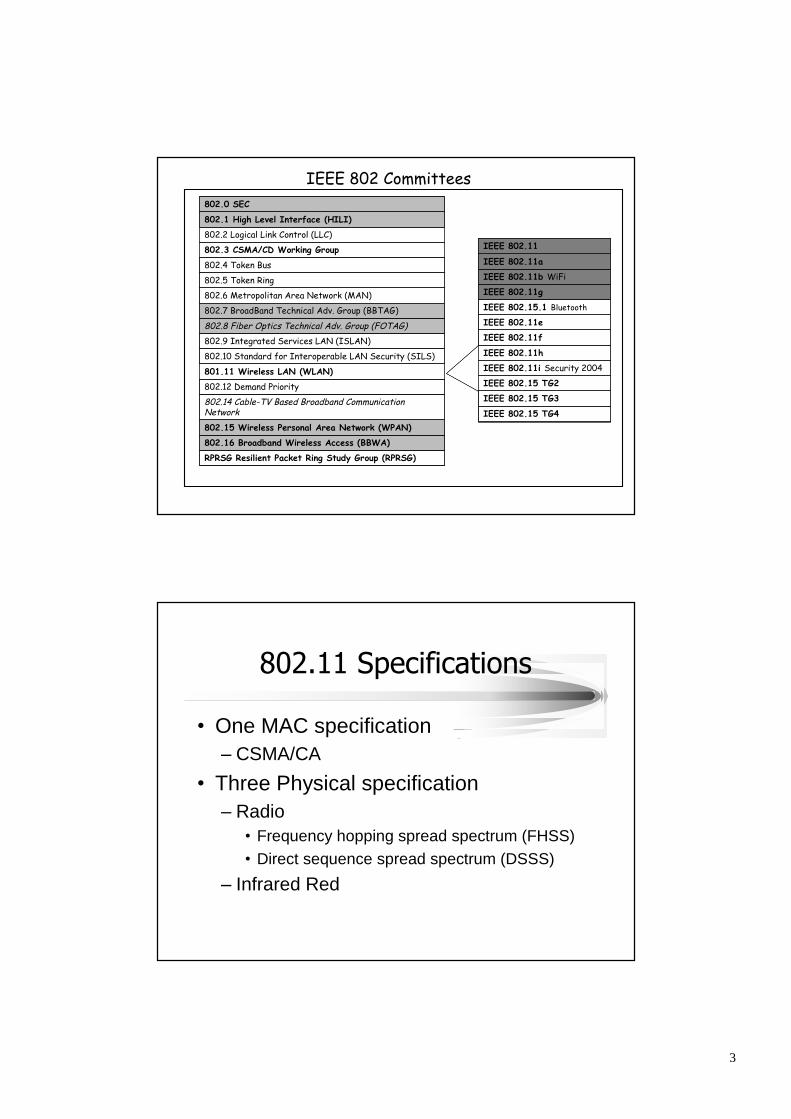
802.6 Metropolitan Area Network (MAN)
RPRSG Resilient Packet Ring Study Group (RPRSG)
802.16 Broadband Wireless Access (BBWA)
802.15 Wireless Personal Area Network (WPAN)
802.14 Cable-TV Based Broadband CommunicationNetwork
802.12 Demand Priority
801.11 Wireless LAN (WLAN)
802.10 Standard for Interoperable LAN Security (SILS)
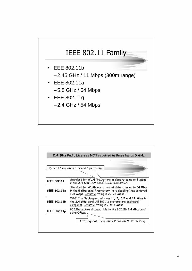
802.11a backward compatible to the 802.11b 2.4 GHz bandusing OFDM.IEEE 802.11g
Wi-Fi™ or “high-speed wireless”1, 2, 5.5 and 11 Mbps inthe 2.4 GHz band. All 802.11b systems are backwardcompliant. Realistic rating is 2 to 4 Mbps.
IEEE 802.11b
Standard for WLAN operations at data rates up to 54 Mbpsin the 5 GHz band. Proprietary “rate doubling" has achieved108 Mbps. Realistic rating is 20-26 Mbps.
IEEE 802.11a
Standard for WLAN operations at data rates up to 2 Mbpsin the 2.4 GHz ISM band. DSSS modulation.IEEE 802.11
Direct Sequence Spread Spectrum
Orthogonal Frequency Division Multiplexing
2.4 GHz Radio Licenses NOT required in these bands 5 GHz
5
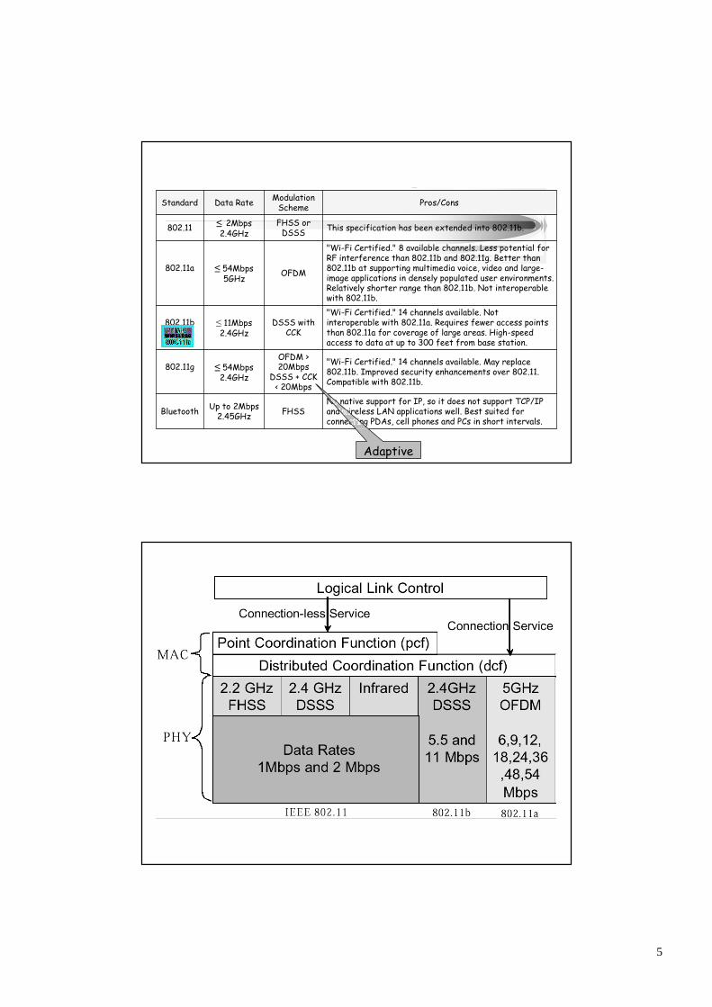
No native support for IP, so it does not support TCP/IPand wireless LAN applications well. Best suited forconnecting PDAs, cell phones and PCs in short intervals.
FHSSUp to 2Mbps2.45GHzBluetooth
"Wi-Fi Certified." 14 channels available. May replace802.11b. Improved security enhancements over 802.11.Compatible with 802.11b.
OFDM >20Mbps
DSSS + CCK< 20Mbps
≤54Mbps2.4GHz
802.11g
"Wi-Fi Certified." 14 channels available. Notinteroperable with 802.11a. Requires fewer access pointsthan 802.11a for coverage of large areas. High-speedaccess to data at up to 300 feet from base station.
DSSS withCCK
≤11Mbps2.4GHz
802.11b
"Wi-Fi Certified." 8 available channels. Less potential forRF interference than 802.11b and 802.11g. Better than802.11b at supporting multimedia voice, video and large-image applications in densely populated user environments.Relatively shorter range than 802.11b. Not interoperablewith 802.11b.
OFDM≤54Mbps5GHz
802.11a
This specification has been extended into 802.11b.FHSS orDSSS
≤2Mbps2.4GHz
802.11
Pros/ConsModulationSchemeData RateStandard
Adaptive
6
Spread Spectrum modulation schemes ease addressproblems, each in their own way.
•DSSS Direct Sequence Spread Spectrum
•OFDM Orthogonal Frequency Division Multiplexing
•FHSS Frequency Hopping Spread Spectrum
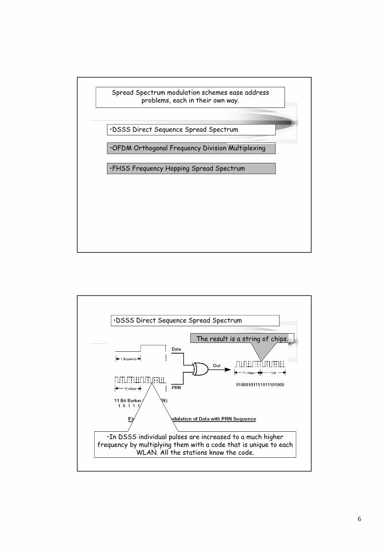
•DSSS Direct Sequence Spread Spectrum
•In DSSS individual pulses are increased to a much higherfrequency by multiplying them with a code that is unique to each
WLAN. All the stations know the code.
The result is a string of chips.
7
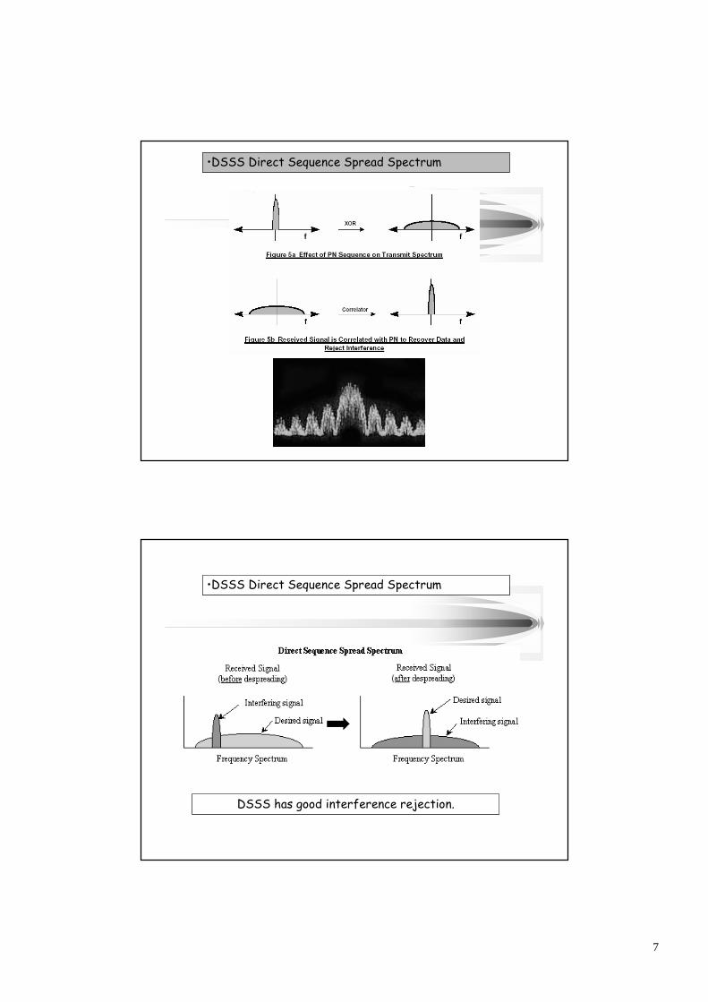
•DSSS Direct Sequence Spread Spectrum
•DSSS Direct Sequence Spread Spectrum
DSSS has good interference rejection.
8
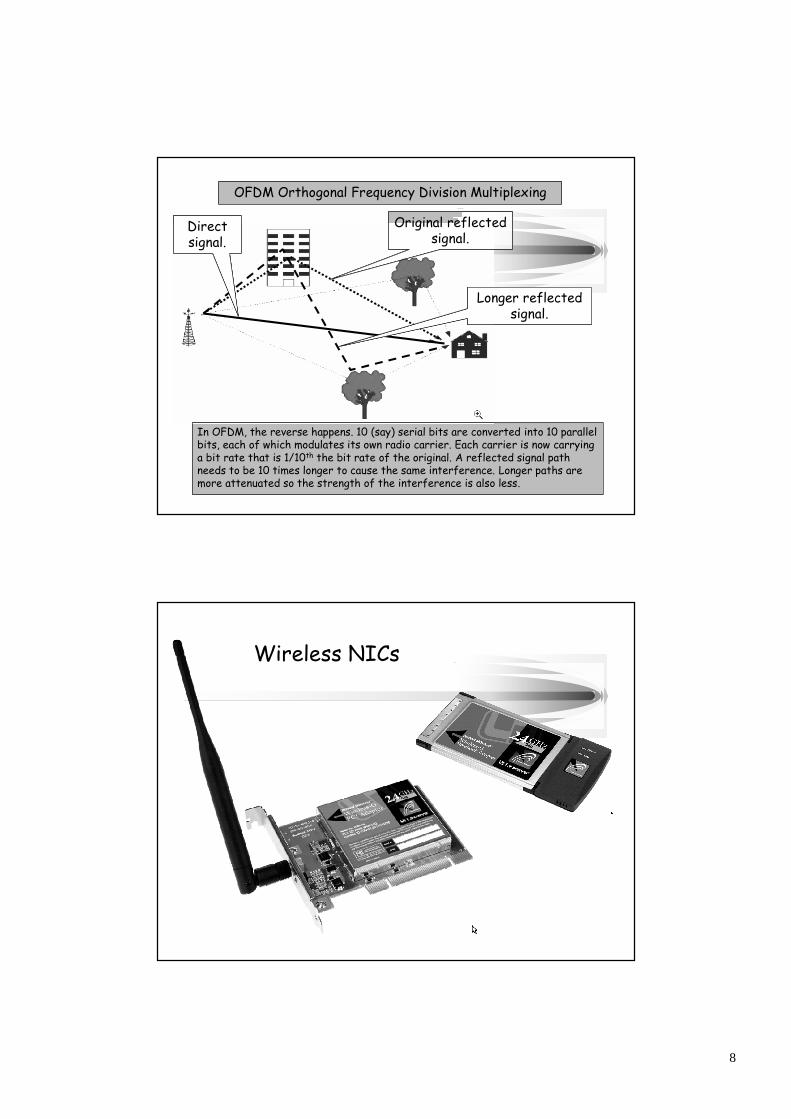
OFDM Orthogonal Frequency Division Multiplexing
In OFDM, the reverse happens. 10 (say) serial bits are converted into 10 parallelbits, each of which modulates its own radio carrier. Each carrier is now carryinga bit rate that is 1/10th the bit rate of the original. A reflected signal pathneeds to be 10 times longer to cause the same interference. Longer paths aremore attenuated so the strength of the interference is also less.
Directsignal.
Longer reflectedsignal.
Original reflectedsignal.
Wireless NICs
9
Access Point (AP)
•Usually connects wireless andwired networks–if not wired
•acts as an extension point(wireless bridge)
•consists of a radio, a wired network interface (e.g.,802.3), and bridging software conforming to the 802.1dbridging standard
•Number of clients supported–device dependent
AP as a Wireless Bridge
mobile terminal
access point
server
fixed terminal
application
TCP
802.11 PHY
802.11 MAC
IP
802.3 MAC
802.3 PHY
Application
TCP
802.3 PHY
802.3 MAC
IP
802.11 MAC
802.11 PHY
LLC
infrastructure network
LLC LLC
10
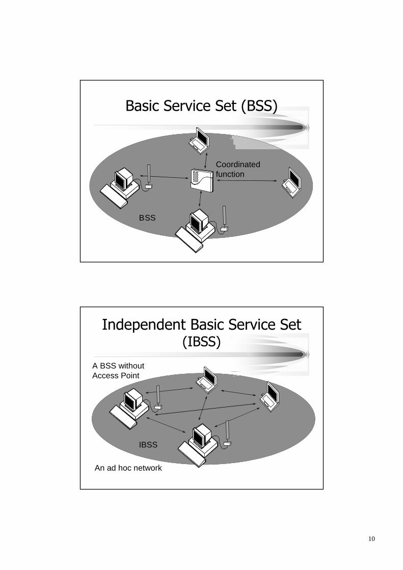
Basic Service Set (BSS)
BSS
Coordinatedfunction
Independent Basic Service Set(IBSS)
IBSS
A BSS withoutAccess Point
An ad hoc network
11
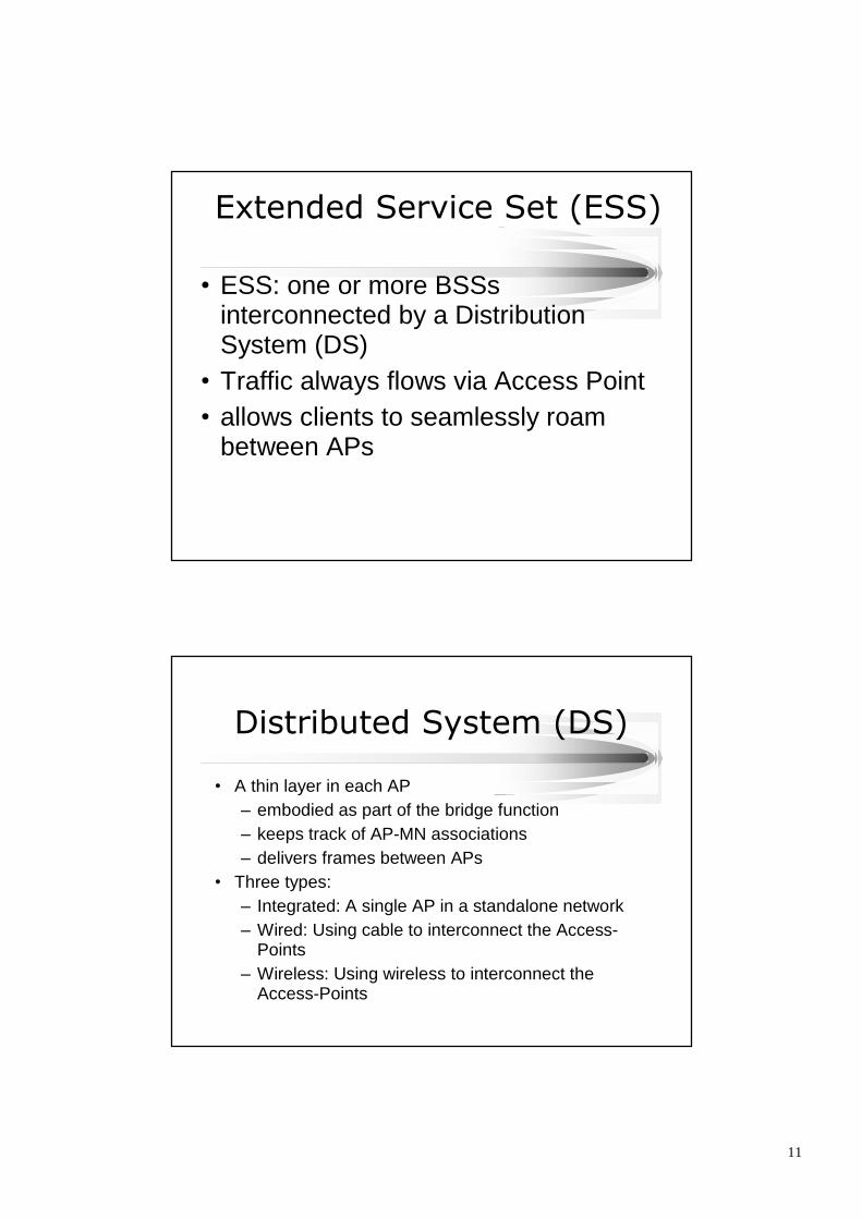
Extended Service Set (ESS)
•ESS: one or more BSSsinterconnected by a DistributionSystem (DS)
•Traffic always flows via Access Point•allows clients to seamlessly roam
between APs
Distributed System (DS)
•A thin layer in each AP–embodied as part of the bridge function–keeps track of AP-MN associations–delivers frames between APs
•Three types:–Integrated: A single AP in a standalone network–Wired: Using cable to interconnect the Access-
Points–Wireless: Using wireless to interconnect the
Access-Points
12
ESS:Single BSS (with integrated DS)
BSS
AccessPoint
A cell
91.44 to 152.4 meters
ESS: BSS’s with WiredDistribution System (DS)
BSS
BSS
DistributionSystem
20-30% overlap
13
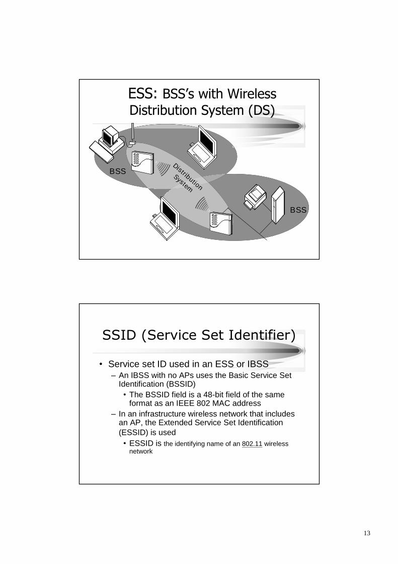
ESS: BSS’s with WirelessDistribution System (DS)
BSS
BSS
Distribution
System
SSID (Service Set Identifier)
•Service set ID used in an ESS or IBSS–An IBSS with no APs uses the Basic Service Set
Identification (BSSID)•The BSSID field is a 48-bit field of the same
format as an IEEE 802 MAC address–In an infrastructure wireless network that includes
an AP, the Extended Service Set Identification(ESSID) is used•ESSID is the identifying name of an 802.11 wireless
network
14
ESSID in an ESS
•ESSID differentiates one WLAN from another•Client must be configured with the right
ESSID to be able to associate itself with aspecific AP
•ESSID is not designed to be part of securitymechanism, and it is unfitted to be one•AP broadcast the SSID(s) they support•Client association requests contain the
ESSID•Transmitted in the clear
Connecting to the NetworkClient Access Point
Probe Request
Probe Response
Authentication Response
Authentication Request
Association Response
Association Request
Probing
802.11Authentication
Association
15
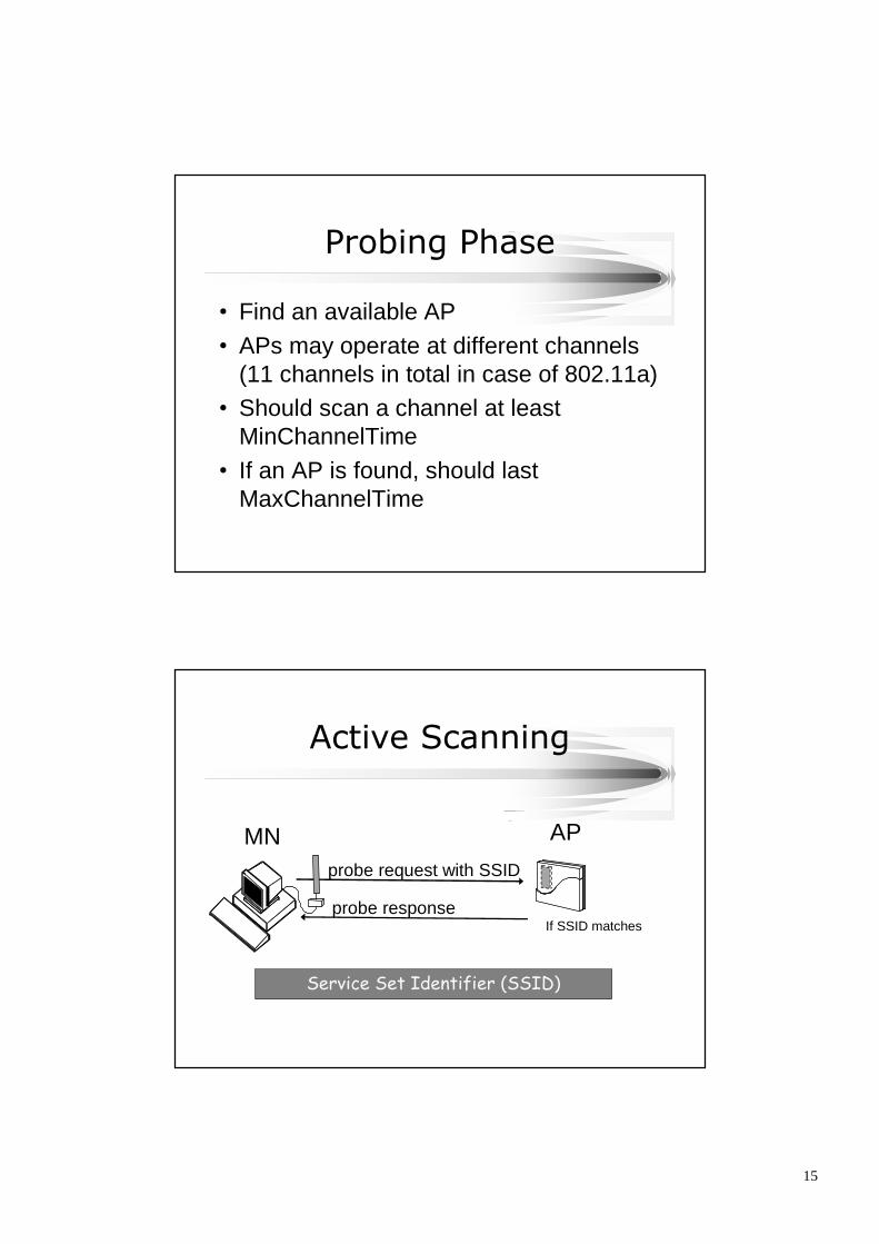
Probing Phase
•Find an available AP•APs may operate at different channels
(11 channels in total in case of 802.11a)•Should scan a channel at least
MinChannelTime•If an AP is found, should last
MaxChannelTime
Active Scanning
probe request with SSID
probe responseIf SSID matches
Service Set Identifier (SSID)
APMN
16
Passive Scanning
beacon with SSID
Service Set Identifier (SSID)
APMN
Full Scanning
MN AP 1
Scan channel 1
AP 2 AP 3
Scan channel 2
Beacon or Probe Resp
MinChannelTime
MaxChannelTime
Scan channel 3
Scan channel 11
…
17
Association & Re-association
•Association: The mapping betweensome AP’s port and an MN
•Association must exist before networkservices can be used
•Wireless LAN Association replaces thephysical link in a wired LAN
•MN may later re-associate to anotherAP with higher signal quality
Authentication andAssociation
Authentication
Unauthenticated and unassociatedThe node is disconnected from thenetwork and not associated to anaccess point.
Authenticated and unassociatedThe node has been authenticatedon the network but has not yetassociated with the access point.
Authenticated and associatedThe node is connected to thenetwork and able to transmit andreceive data through the accesspoint.
18
802.11 AuthenticationMethods
•Open Authentication (standard)
•Shared key authentication (standard)
•MAC Address authentication (commonlyused)
Open Authentication•The authentication request contain a NULL
authentication protocol. It must have the APSSID.
•The access point will grant any request forauthenticationClient Access Point
Authentication Request
Authentication response
19
Shared Key Authentication•Requires that the client configures a static WEP key
Client Access Point
Authentication Request
Authentication response (challenge)
Authentication response(Success/Failure)
Authentication Request(encrypted challenge)
MAC Address Authentication•Not specified in the 802.11 standard, but
supported by many vendors (e.g. Cisco)•Can be added to open and shared key
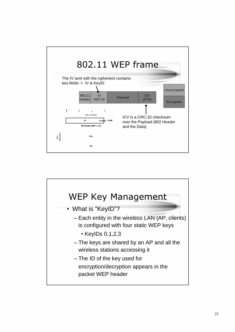
The IV sent with the ciphertext containstwo fields: = IV & KeyID
ICV is a CRC-32 checksumover the Payload (802 Headerand the Data)
WEP Key Management•What is “KeyID”?
–Each entity in the wireless LAN (AP, clients)is configured with four static WEP keys
•KeyIDs 0,1,2,3
–The keys are shared by an AP and all thewireless stations accessing it
–The ID of the key used forencryption/decryption appears in thepacket WEP header
22
RC4 key
IV(3 octets) Secret Key (5 or 13 octets)
•Standard: 24 + 40 = 64 bit RC4 key
•Vendors: 24 + 104 = 128 bit RC4 key
•We’ll see that key-size doesn’t prevent the attacks
Details - Checksum•CRC-32 - detecting single random bit
errors
•If CRC is correct, WEP assumes
–Packet has not been modified
–Packet is from authorized user
•Linear Property:
CRC (XOR(A,B)) = XOR(CRC (A), CRC(B))
23
RC4•Developed by Rivest in 1987
•Kept as a trade secret (but leaked in 1994)
•Key can be between 1 and 256 bytes
•Used as a simple and fast generator of pseudo-random sequences of bytes (to be used as “one-time-pad”)
•Should discard first 256 bytes of generated pad
•Passes all usual randomness tests
802.11 Vulnerabilities
•RC 4 stream ciper not suited for data with lots ofpacket loss
•Loss of data requires re-synch, new key everytime
•Poor key management–WEP uses same key for authentication/encryption–Provides no mechanism for session key refreshing
•one-way authentication:–has no provision for MNs to authenticate/verify the
integrality of AP
24
Weaknesses of WEP:Overall Key Space is Too Small
•IV change per packet is OPTIONAL–If the “IV || key”for RC4 is changed
for every 802.11 packet, repeatedpatterns can occur more frequently
–at the rate of 11 Mbps of 1,500bytes/packet, all key space will beexhausted in about 5 hours.
802.1X•based on EAP (extensible
authentication protocol, RFC 2284)–still one-way authentication–initially, MN is in an unauthorized port–an “authentication server”exists–after authorized, the MH enters an
authorized port–802.1X ties it to the physical medium,
be it Ethernet, Token Ring orwireless LAN.
25
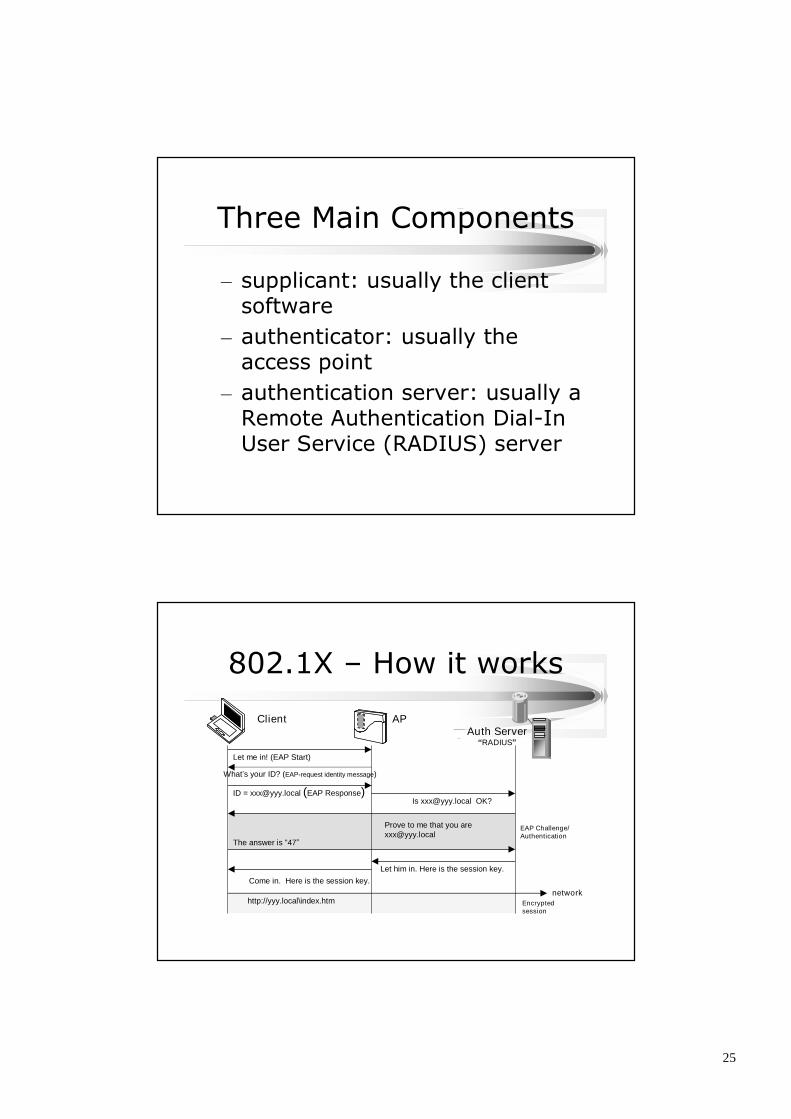
Three Main Components
–supplicant: usually the clientsoftware
–authenticator: usually theaccess point
–authentication server: usually aRemote Authentication Dial-InUser Service (RADIUS) server
Let him in. Here is the session key.Come in. Here is the session key.
http://yyy.local\index.htmnetwork
EAP Challenge/Authentication
Encryptedsession
26
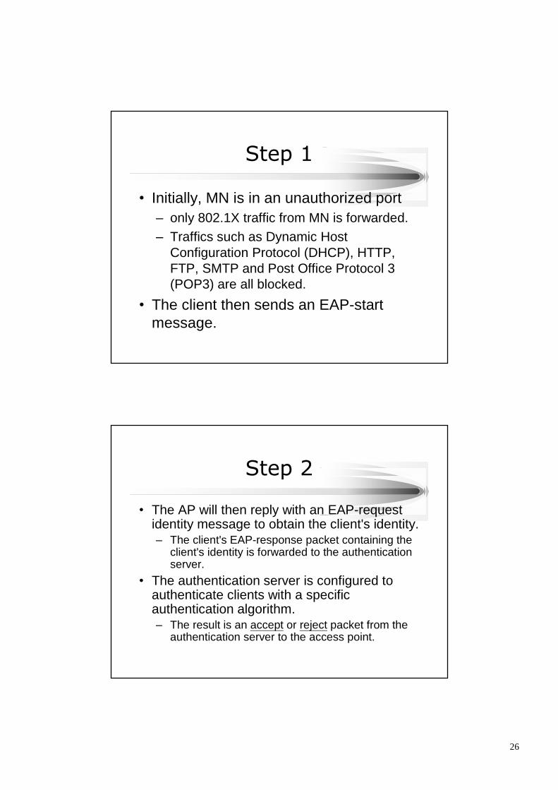
Step 1
•Initially, MN is in an unauthorized port–only 802.1X traffic from MN is forwarded.–Traffics such as Dynamic Host
Configuration Protocol (DHCP), HTTP,FTP, SMTP and Post Office Protocol 3(POP3) are all blocked.
•The client then sends an EAP-startmessage.
Step 2
•The AP will then reply with an EAP-requestidentity message to obtain the client's identity.– The client's EAP-response packet containing the
client's identity is forwarded to the authenticationserver.
•The authentication server is configured toauthenticate clients with a specificauthentication algorithm.– The result is an accept or reject packet from the
authentication server to the access point.
27
Steps 3 and 4
•Upon receiving the accept packet, the AP willtransit the client's port to an authorized state,– then all traffic will be forwarded.
•Notes:– 802.1X for wireless LANs makes NO mention of
key distribution or management.•This is left for vendor implementation.
– At logoff, the client will send an EAP-logoffmessage to force the AP to transit the client portto an unauthorized state.
802.11 Key Management•Key Management:
–BKR (broadcast key rotation)•AP periodically broadcasts WEP shared key•The initial WEP key only used for registration at
the first time.–So the WEP key is used less frequently.
–TKIP (temporal key integrity protocol)•hashing the key before using it for encrypting a
packet
28
MAC Management Layer
•Synchronization–Time Synchronization Function (TSF)
•Power Management–Sleeping without missing any messages–Power management functions