16
Introduction to Ingot Niobium Andrew Hutton SSTIN10 Symposium Jefferson Lab Sept 22-24, 2010
| Date post: | 16-Dec-2015 |
| Category: |
Documents |
| Upload: | agustin-poyner |
| View: | 221 times |
| Download: | 1 times |
Introduction to Ingot Niobium
Andrew Hutton
SSTIN10 Symposium Jefferson LabSept 22-24, 2010

• Introduction to CEBAF
• Historical perspectives on ingot niobium – 1970’s
• Reintroduction of ingot niobium - 2004
• Conclusions
Overview

Jefferson Lab Accelerator Site CEBAF SRF recirculating
linacTest Lab at the Institute for Superconducting Radio-Frequency
Science and Technology- SNS drive linac
- JLab - FEL FEL
Nuclear PhysicsDetector
Halls A, B, C
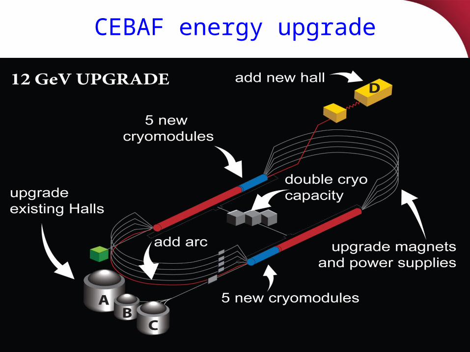
CEBAF energy upgrade

Highlights of Early SRF Technology• Cavities were mostly made from ingot niobium
• Process and procedures were similar and as varied as today• Reactor grade Niobium material in ingot, bar, plate sheet and
tube form was available • Achievable gradient limited by multipacting and/or field emission• Residual surface resistance (nΩ) was not well understood
• Still the case • At highest frequencies (Electropolished fine grain, X-band) Hpk ~
159 mT Q0 ~5x10⁹ • (BCP’d ingot Nb, 1970’s) Hpk ~ 108 mT & Q0 ~1×10¹¹ @ 1.2 K CW• For comparison (CEBAF upgrade spec.) Hpk ~ 92 mT Q0 ~ 7×10⁹
@ 2 K CW (2008)

Historical Example of Ingot Niobium 1
Stanford solid niobium cavity 1970
Hpk~ 108 mT with BCP

Historical Example of Ingot Niobium 2
Siemens solid niobium cavity 1973
Hpk~ 109 mT with BCP
Hpk~ 130 mT with EP

UIUC HEPL 49 Pill Box 1.3 GHz Cavities
Photo Courtesy of Larry Cardman
Hpk/Eacc ~ 3
• Gradient limitation was considered to be due to inadequate cleaning• Surface recontamination from dirty vacuum systems was not
thought to be important• Shape was changed to elliptical Hpk/Eacc ~ 4.7 (CEBAF Cavities)• Polycrystalline Niobium became the material of choice
Cavities were machined from low purity ingotsFinal step was ~1800 ºC vacuum anneal to reduceresidual stress

Birth of Ingot Niobium Technology CBMM/RMCI-JLab CRADA, August 2004
Comparison of Single and Poly Crystal RRR niobium
0
200
400
600
800
1000
1200
0 20 40 60 80 100 120
Percentage of elongatioon
Lo
ad (
Po
un
ds)
Poly Crystal
Single Crystal
Chosen for Excellent Ductility and Surface Smoothness with just BCP
First CBMM/JLab International Patents were applied for in April, 2005
September 2004
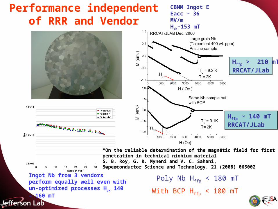
Performance independent of RRR and Vendor
CBMM Ingot E Eacc ~ 36 MV/mHpk~153 mT
Hffp ~ 140 mT RRCAT/JLab
1.E+09
1.E+10
1.E+11
0 5 10 15 20 25 30 35 40
Eacc [MV/m]
Qo
"Heraeus"
"CBMM"
"Ningxia"
Ingot Nb from 3 vendors perform equally well even with un-optimized processes Hpk 140 – 160 mT
Poly Nb Hffp < 180 mT
Hffp > 210 mT RRCAT/JLab
With BCP Hffp < 100 mT
“On the reliable determination of the magnetic field for first flux-linepenetration in technical niobium material”S. B. Roy, G. R. Myneni and V. C. Sahani, Superconductor Science and Technology. 21 (2008) 065002

Figure of merit of large & fine grain Niobium
0.00E+00
1.00E+11
2.00E+11
3.00E+11
4.00E+11
5.00E+11
6.00E+11
0 200 400 600 800 1000
Tantalum Content (Wt ppm)
Qo
.Eac
c (M
V/m
)
Prior to heat treatment
After heat treatment
0.00E+00
5.00E+10
1.00E+11
1.50E+11
2.00E+11
2.50E+11
3.00E+11
0 200 400 600 800 1000 1200 1400
Tanatlum Contenet (wt ppm)
Fig
ure
of
Mer
it (
Qo
.Eac
c) (
MV
/m)
Figure of merit is the product of (Eacc* Qo) at the quench limitCurrently magneto thermal quench limits the performance Polycrystalline niobiumLarge grain ingot niobium
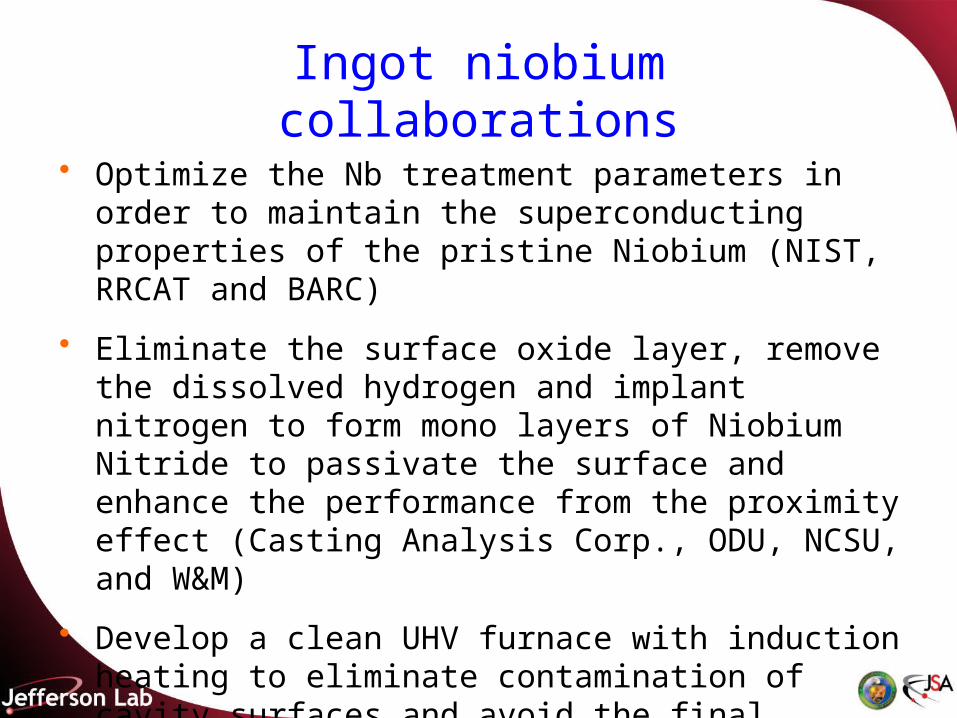
Ingot niobium collaborations
• Optimize the Nb treatment parameters in order to maintain the superconducting properties of the pristine Niobium (NIST, RRCAT and BARC)
• Eliminate the surface oxide layer, remove the dissolved hydrogen and implant nitrogen to form mono layers of Niobium Nitride to passivate the surface and enhance the performance from the proximity effect (Casting Analysis Corp., ODU, NCSU, and W&M)
• Develop a clean UHV furnace with induction heating to eliminate contamination of cavity surfaces and avoid the final chemistry (Casting Analysis Corporation)


Conclusions
• JLab introduced ingot niobium technology and has reconfirmed the high quality factors and peak magnetic fields found with low RRR solid niobium in the 1970’s
• High tantalum in ingot niobium is not expected to negatively impact the performance of the cavities but will reduce the cost of accelerator structures considerably
• Optimized low cost CW linacs built with ingot niobium will pave the path for future R&D and industrial applications

R&D on Ingot Niobium Continues
• The next talks will highlight progress on three continents
• R&Ds in Asia on large/single crystal niobium after the international niobium workshop 2006• Kenji Saito
• Advances in large grain resonators activities at DESY, W.C. Heraeus and RI• Waldemar Singer
• America's overview of superconducting science and technology of ingot niobium• Gigi Ciovati


