86
Introduction to Loop Heat Pipes Jentung Ku NASA/ Goddard Space Flight Center GSFC· 2015 Introduction to LHP - Ku 2015 TFAWS
Introduction to Loop Heat Pipesp p
Jentung KugNASA/ Goddard Space Flight Center
GSFC· 2015
Introduction to LHP - Ku 2015 TFAWS
Outline
• From Heat Pipe to Loop Heat Pipe and Capillary Pumped Loop
• LHP Operating PrinciplesLHP Operating Principles• LHP Components Sizing and Fluid Inventory• LHP Operating Temperature Control• LHP Start-up and Shutdown• LHP Analytical Modeling• Recent LHP Technology Developments• Recent LHP Technology Developments• Summary
Introduction to LHP - Ku 2015 TFAWS 2
Heat Pipes - Heat Transport Limit• For proper heat pipe operation, the
L L total pressure drop must not exceed its capillary pressure head .
Ptot ≤ Pcap,max
Ptot = Pvap+ Pliq + Pg
Liquid Flow
Heat SinkHeat Source
wall
LeLa Lc
Pcap,max = cos/Rp
• Heat Transport Limit– (QL)max = QmaxLeff
– Leff = 0.5 Le + La + 0.5 Lc
wallLiquid Flow
Evaporator CondenserAdiabaticS ti
Vapor Flow
VaporVapor
eff e a c
– (QL)max measured in watt-inches or watt-meters
• Capillary pressure head:
P 1/ R
Section SectionSection
LiquidPressure DropPr
essu
re CapillaryPressure
VaporPressure Drop
Liquid
Li id
Pcap 1/ Rp
• Liquid pressure drop:
Pliq 1/ Rp2
A ti l di i t f
Le La Lc
LiquidNo Gravity Force
Adverse Gravity Force
• An optimal pore radius exists for maximum heat transport.
• Limited heat transport capability
• Limited pumping head against gravity
Introduction to LHP - Ku 2015 TFAWS 3
Distance
b) Vapor and liquid pressure distributions
p p g g g y
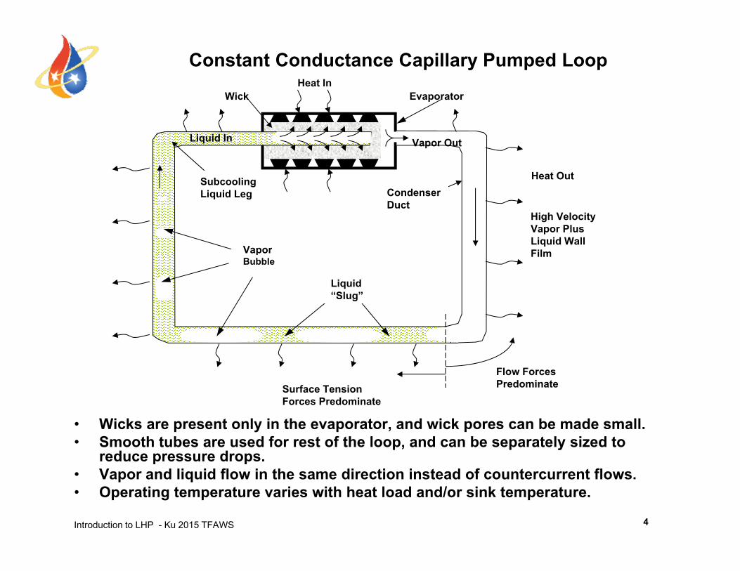
EvaporatorWickHeat In
Constant Conductance Capillary Pumped Loop
S
Vapor Out
Heat Out
Liquid In
Vapor
SubcoolingLiquid Leg Condenser
Duct
Heat Out
High VelocityVapor PlusLiquid WallFilVapor
Bubble
Liquid“Slug”
Film
Flow ForcesPredominateSurface Tension
Forces Predominate
• Wicks are present only in the evaporator, and wick pores can be made small.• Smooth tubes are used for rest of the loop, and can be separately sized to
reduce pressure drops.
Introduction to LHP - Ku 2015 TFAWS
• Vapor and liquid flow in the same direction instead of countercurrent flows.• Operating temperature varies with heat load and/or sink temperature.
4
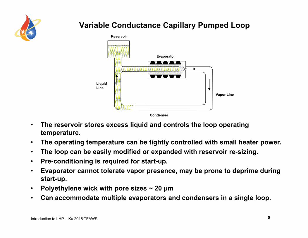
Variable Conductance Capillary Pumped Loop Reservoir
Evaporator
Liquid Line
Vapor Line
• The reservoir stores excess liquid and controls the loop operating temperature.
Condenser
temperature.• The operating temperature can be tightly controlled with small heater power. • The loop can be easily modified or expanded with reservoir re-sizing.• Pre-conditioning is required for start-up.g q p• Evaporator cannot tolerate vapor presence, may be prone to deprime during
start-up.• Polyethylene wick with pore sizes ~ 20 µm
Introduction to LHP - Ku 2015 TFAWS 5
• Can accommodate multiple evaporators and condensers in a single loop.
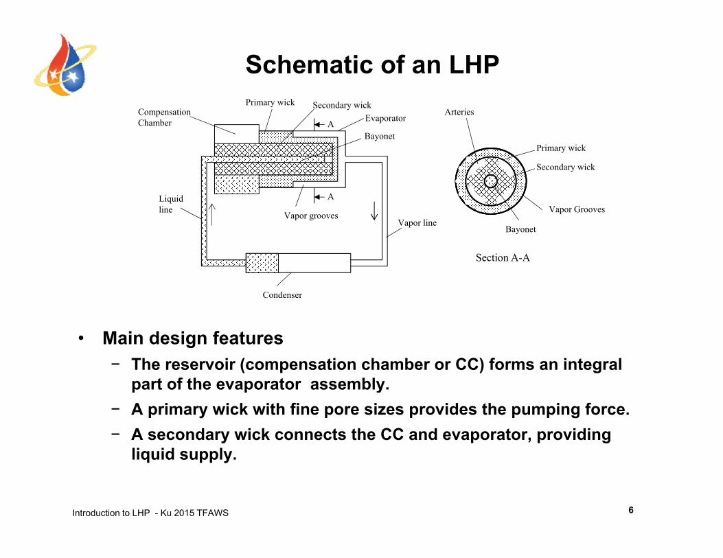
Schematic of an LHPPrimary wick S d i k
Secondary wick
Primary wick
ArteriesCompensationChamber Evaporator
BayonetA
Primary wick Secondary wick
Bayonet
Vapor GroovesVapor line
Vapor grooves
Liquidline
A
Section A-A
Condenser
• Main design features− The reservoir (compensation chamber or CC) forms an integral
part of the evaporator assemblypart of the evaporator assembly.− A primary wick with fine pore sizes provides the pumping force.− A secondary wick connects the CC and evaporator, providing
liquid supply
Introduction to LHP - Ku 2015 TFAWS
liquid supply.
6
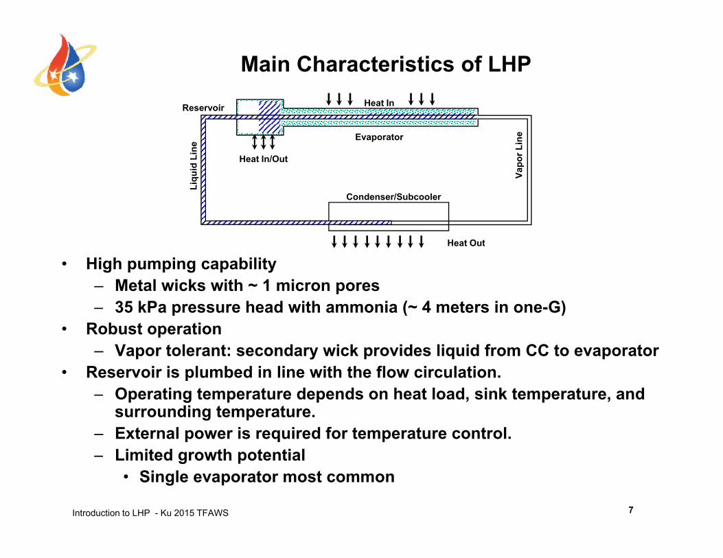
Main Characteristics of LHPHeat In
Vapo
r Lin
e
uid
Line
Evaporator
Heat In/Out
Reservoir Heat In
Condenser/Subcooler
V
Liqu
Heat Out
• High pumping capability– Metal wicks with ~ 1 micron pores– 35 kPa pressure head with ammonia (~ 4 meters in one-G)
Heat Out
p ( )• Robust operation
– Vapor tolerant: secondary wick provides liquid from CC to evaporator• Reservoir is plumbed in line with the flow circulation.
– Operating temperature depends on heat load, sink temperature, and surrounding temperature.
– External power is required for temperature control.Limited growth potential
Introduction to LHP - Ku 2015 TFAWS
– Limited growth potential• Single evaporator most common
7
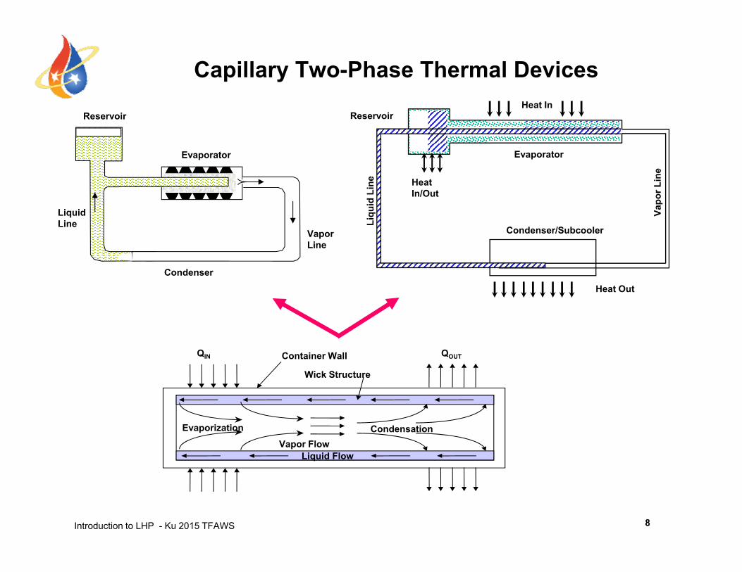
Capillary Two-Phase Thermal DevicesHeat In
Reservoir
Evaporator
nee
Evaporator
ReservoirHeat In
Liquid Line
Vapor Line
Condenser/Subcooler
Vapo
r Lin
Liqu
id L
ine Heat
In/Out
Condenser
Heat Out
Wick Structure
Container Wall QOUTQIN
Liquid FlowVapor Flow
CondensationEvaporization
Introduction to LHP - Ku 2015 TFAWS 8
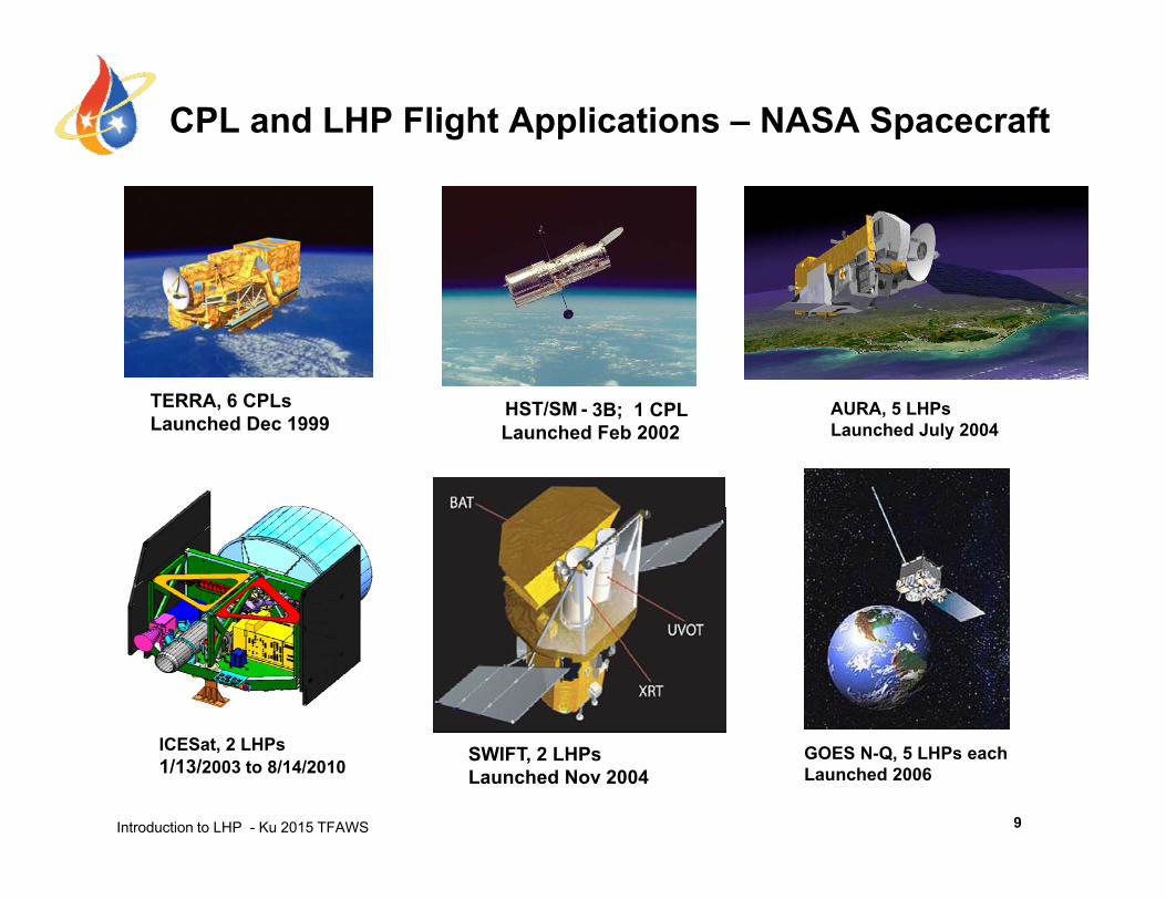
CPL and LHP Flight Applications – NASA Spacecraft
TERRA 6 CP HST/SM - 3B; 1 CPLLaunched Feb 2002
TERRA, 6 CPLsLaunched Dec 1999
AURA, 5 LHPsLaunched July 2004
Introduction to LHP - Ku 2015 TFAWS 9
ICESat, 2 LHPs1/13/2003 to 8/14/2010
SWIFT, 2 LHPsLaunched Nov 2004
GOES N-Q, 5 LHPs eachLaunched 2006
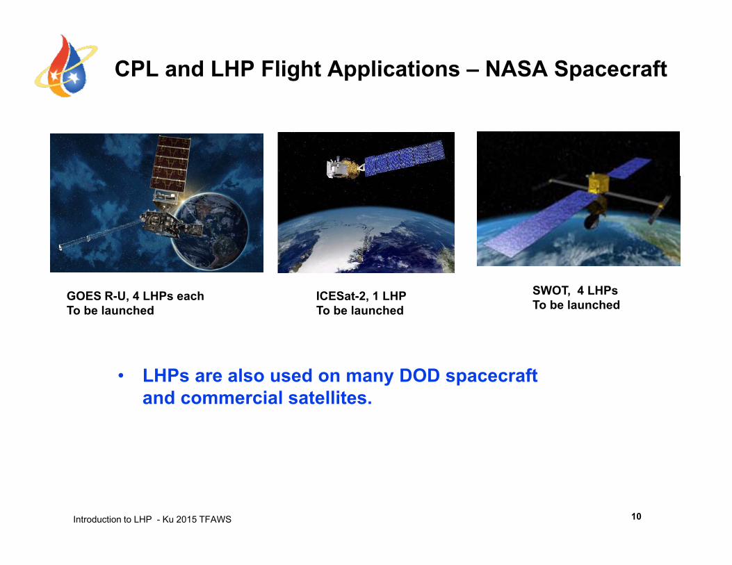
CPL and LHP Flight Applications – NASA Spacecraft
SWOT, 4 LHPsTo be launched
GOES R-U, 4 LHPs eachTo be launched
ICESat-2, 1 LHPTo be launched
• LHPs are also used on many DOD spacecraft and commercial satellites.
Introduction to LHP - Ku 2015 TFAWS 10
Outline
• From Heat Pipe to Loop Heat Pipe and Capillary Pumped Loop
• LHP Operating PrinciplesLHP Operating Principles• LHP Components Sizing and Fluid Inventory• LHP Operating Temperature Control• LHP Start-up and Shutdown• LHP Analytical Modeling• Recent LHP Technology Developments• Recent LHP Technology Developments• Summary
Introduction to LHP - Ku 2015 TFAWS 2
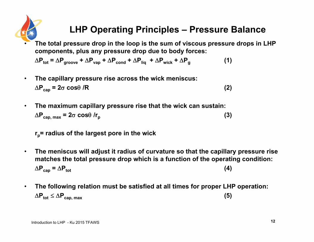
• The total pressure drop in the loop is the sum of viscous pressure drops in LHP
LHP Operating Principles – Pressure BalanceThe total pressure drop in the loop is the sum of viscous pressure drops in LHP components, plus any pressure drop due to body forces:Ptot = Pgroove + Pvap + Pcond + Pliq + Pwick + Pg (1)
• The capillary pressure rise across the wick meniscus: Pcap = 2 cos /R (2)
• The maximum capillary pressure rise that the wick can sustain:• The maximum capillary pressure rise that the wick can sustain: Pcap, max = 2 cos /rp (3)
rp= radius of the largest pore in the wickp g p
• The meniscus will adjust it radius of curvature so that the capillary pressure rise matches the total pressure drop which is a function of the operating condition: P P (4)Pcap = Ptot (4)
• The following relation must be satisfied at all times for proper LHP operation:Ptot Pcap max (5)
Introduction to LHP - Ku 2015 TFAWS
Ptot Pcap, max (5)
12
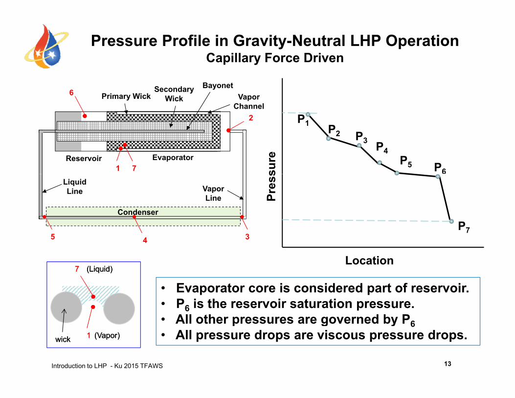
Pressure Profile in Gravity-Neutral LHP Operation Capillary Force Driven
P1
Vapor Channel
Primary WickSecondary
WickBayonet
2
6
1 P2 P3 P4P5 P6su
reReservoir Evaporator1 7
Pres
s
P
Vapor Line
Liquid Line
Condenser
Location
P7
77 (Liquid)(Liquid)
35 4
• Evaporator core is considered part of reservoir.• P6 is the reservoir saturation pressure.• All other pressures are governed by P6
Introduction to LHP - Ku 2015 TFAWS
p g y 6• All pressure drops are viscous pressure drops.
13
11wickwick (Vapor)(Vapor)
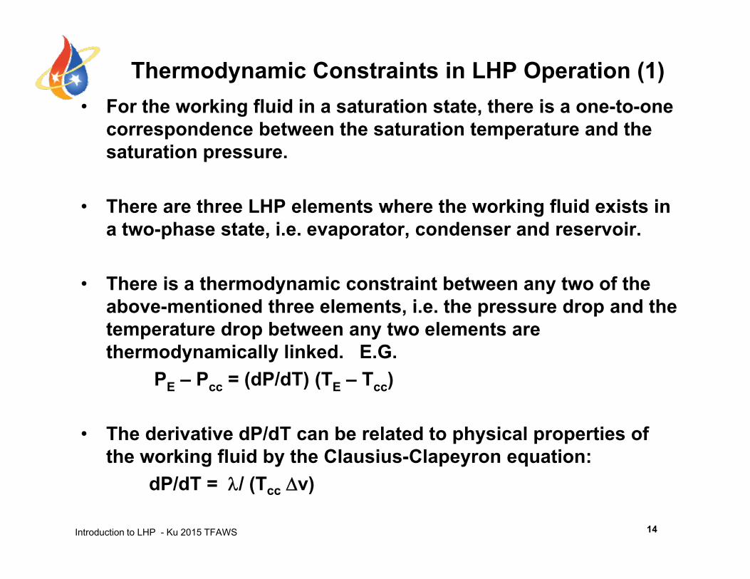
Thermodynamic Constraints in LHP Operation (1)• For the working fluid in a saturation state there is a one-to-one• For the working fluid in a saturation state, there is a one-to-one
correspondence between the saturation temperature and the saturation pressure.
• There are three LHP elements where the working fluid exists in a two-phase state, i.e. evaporator, condenser and reservoir.
• There is a thermodynamic constraint between any two of the above-mentioned three elements, i.e. the pressure drop and the temperature drop between any two elements aretemperature drop between any two elements are thermodynamically linked. E.G.
PE – Pcc = (dP/dT) (TE – Tcc)
• The derivative dP/dT can be related to physical properties of the working fluid by the Clausius-Clapeyron equation:
Introduction to LHP - Ku 2015 TFAWS
dP/dT = / (Tcc v)
14
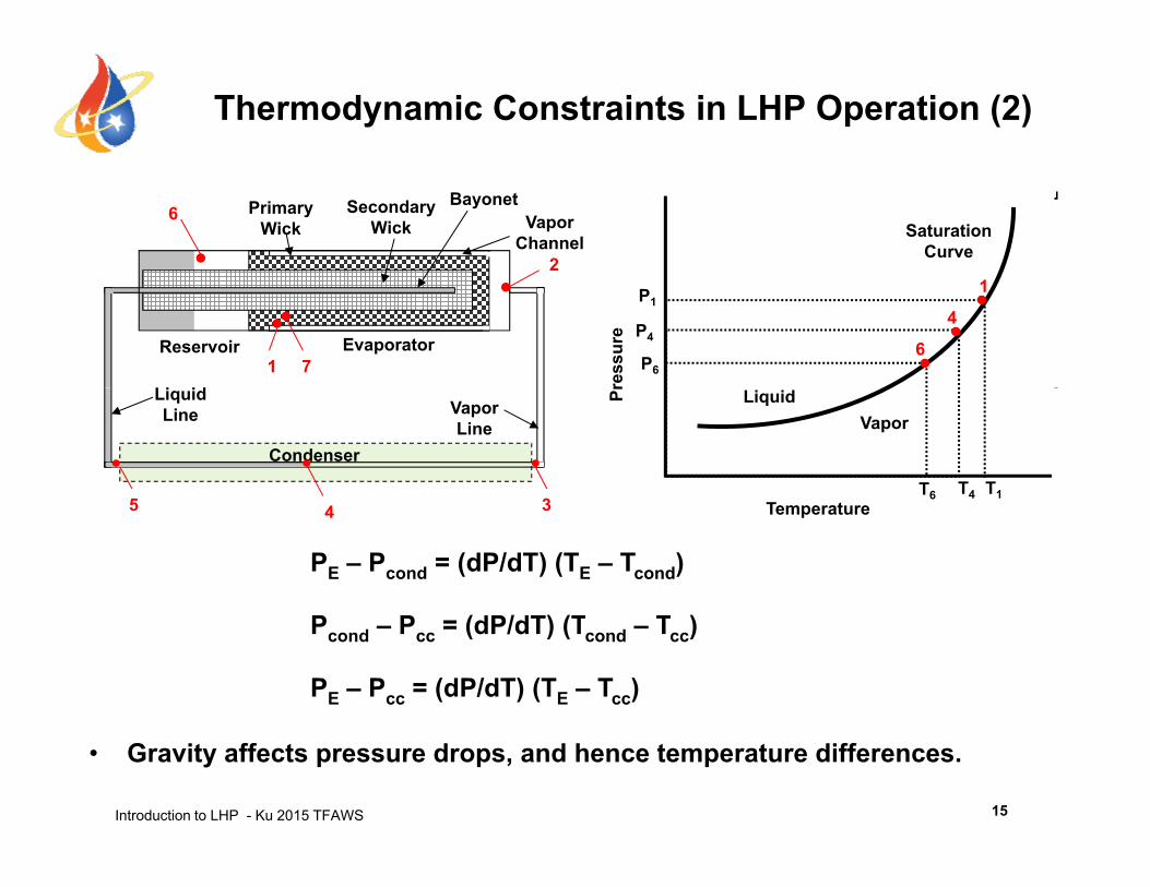
Thermodynamic Constraints in LHP Operation (2)
Vapor Channel
Primary Wick
Secondary Wick
Bayonet
2
6
Saturation Curve
Reservoir Evaporator
Li id1 7
ress
ure P4
P1
P6
6
1
4
Vapor Line
Liquid Line
Condenser
35
Pr
T4 T1
VaporLiquid
T6
PE – Pcond = (dP/dT) (TE – Tcond)
35 4 Temperature
Pcond – Pcc = (dP/dT) (Tcond – Tcc)
PE – Pcc = (dP/dT) (TE – Tcc)
Introduction to LHP - Ku 2015 TFAWS 15
• Gravity affects pressure drops, and hence temperature differences.
Outline
• From Heat Pipe to Loop Heat Pipe and Capillary Pumped Loop
• LHP Operating PrinciplesLHP Operating Principles• LHP Components Sizing and Fluid Inventory• LHP Operating Temperature Control• LHP Start-up• LHP Shutdown • LHP Analytical Modeling• LHP Analytical Modeling• Recent LHP Technology Developments• Summary
Introduction to LHP - Ku 2015 TFAWS 2
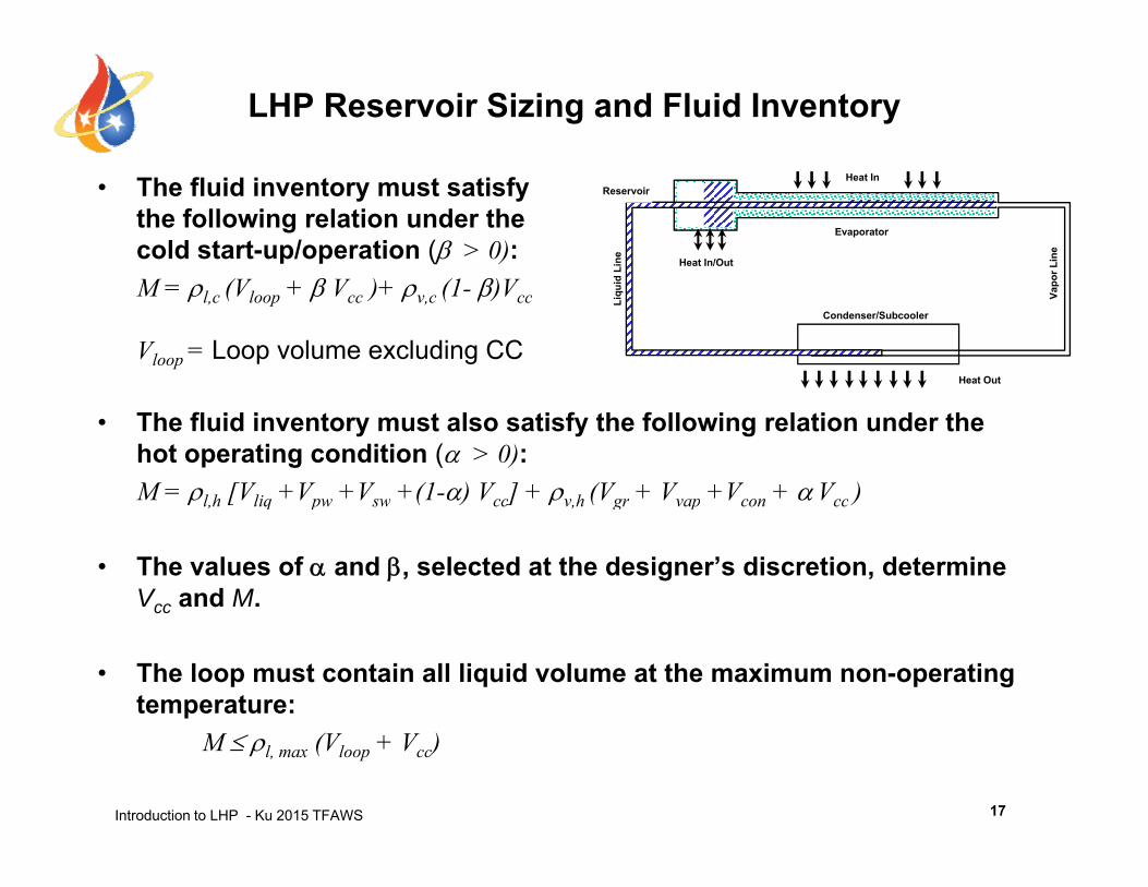
LHP Reservoir Sizing and Fluid Inventory
• The fluid inventory must satisfy the following relation under the cold start-up/operation ( > 0):
or L
ine
d Li
ne
Evaporator
Heat In/Out
ReservoirHeat In
M = l,c (Vloop + Vcc )+ v,c (1- )Vcc
Vloop = Loop volume excluding CCCondenser/Subcooler
Vapo
Liqu
id
Heat Out
• The fluid inventory must also satisfy the following relation under the hot operating condition ( > 0):M = l h [Vliq +Vpw +Vsw +(1-) Vcc] + v h (Vgr + Vvap +Vcon + Vcc )M l,h [Vliq Vpw Vsw (1 ) Vcc] v,h (Vgr Vvap Vcon Vcc )
• The values of and , selected at the designer’s discretion, determine Vcc and M.cc
• The loop must contain all liquid volume at the maximum non-operating temperature:
Introduction to LHP - Ku 2015 TFAWS
M l, max (Vloop + Vcc)
17
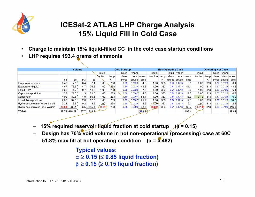
ICESat-2 ATLAS LHP Charge Analysis 15% Liquid Fill in Cold Caseq
• Charge to maintain 15% liquid-filled CC in the cold case startup conditions• LHP requires 193.4 grams of ammonia
Volume Cold Start-up Non-Operating Case Operating Hot Caseliquid liquid vapor liquid liquid vapor liquid liquid vapor
fraction temp dens dens mass fraction temp dens dens mass fraction temp dens dens massin3 cc in3 cc K gm/cc gm/cc gms K gm/cc gm/cc gms K gm/cc gm/cc gms
Evaporator (vapor) 0.43 7.1 0.4 7.1 1.00 268 0.65 0.0029 4.6 1.00 333 0.54 0.0213 3.8 0.00 313 0.57 0.0126 0.1Evaporator (liquid) 4 67 76 5 4 7 76 5 1 00 268 0 65 0 0029 49 5 1 00 333 0 54 0 0213 41 1 1 00 313 0 57 0 0126 43 6Evaporator (liquid) 4.67 76.5 4.7 76.5 1.00 268 0.65 0.0029 49.5 1.00 333 0.54 0.0213 41.1 1.00 313 0.57 0.0126 43.6Liquid Core 0.69 11.2 0.7 11.2 1.00 268 0.65 0.0029 7.3 1.00 333 0.54 0.0213 6.0 1.00 313 0.57 0.0126 6.4Vapor transport line 1.28 21.0 1.3 21.0 1.00 233 0.69 0.0007 14.0 1.00 333 0.54 0.0213 11.3 0.00 313 0.57 0.0126 0.3Condenser 4.92 80.6 4.9 80.6 1.00 233 0.69 0.0007 55.4 1.00 333 0.54 0.0213 43.3 0.12 313 0.57 0.0126 6.2Liquid Transport Line 2.00 32.8 2.0 32.8 1.00 233 0.69 0.0007 21.9 1.00 333 0.54 0.0213 17.6 1.00 313 0.57 0.0126 18.7Hydro-accumulator Wicks Liquid 0.24 3.9 0.2 3.9 1.00 268 0.65 0.0029 2.5 1.00 333 0.54 0.0213 2.1 1.00 313 0.57 0.0126 2.2Hydro-accumulator Free Volume 23.50 385.1 23.5 385.1 0.15 268 0.65 0.0029 38.3 0.302 333 0.54 0.0213 68.2 0.518 313 0.57 0.0126 116.0
TOTAL 37 72 618 27 37 7 618 3 193 4 193 4 193 4
– 15% required reservoir liquid fraction at cold startup (β = 0.15)– Design has 70% void volume in hot non-operational (processing) case at 60C
TOTAL 37.72 618.27 37.7 618.3 193.4 193.4 193.4
g p (p g)– 51.8% max fill at hot operating condition (α = 0.482)
Typical values: 0.15 ( 0.85 liquid fraction)
Introduction to LHP - Ku 2015 TFAWS
0.15 ( 0.15 liquid fraction)
18
Outline
• From Heat Pipe to Loop Heat Pipe and Capillary Pumped Loop
• LHP Operating PrinciplesLHP Operating Principles• LHP Components Sizing and Fluid Inventory• LHP Operating Temperature Control• LHP Start-up and Shutdown• LHP Analytical Modeling• Recent LHP Technology Developments• Recent LHP Technology Developments• Summary
Introduction to LHP - Ku 2015 TFAWS 2
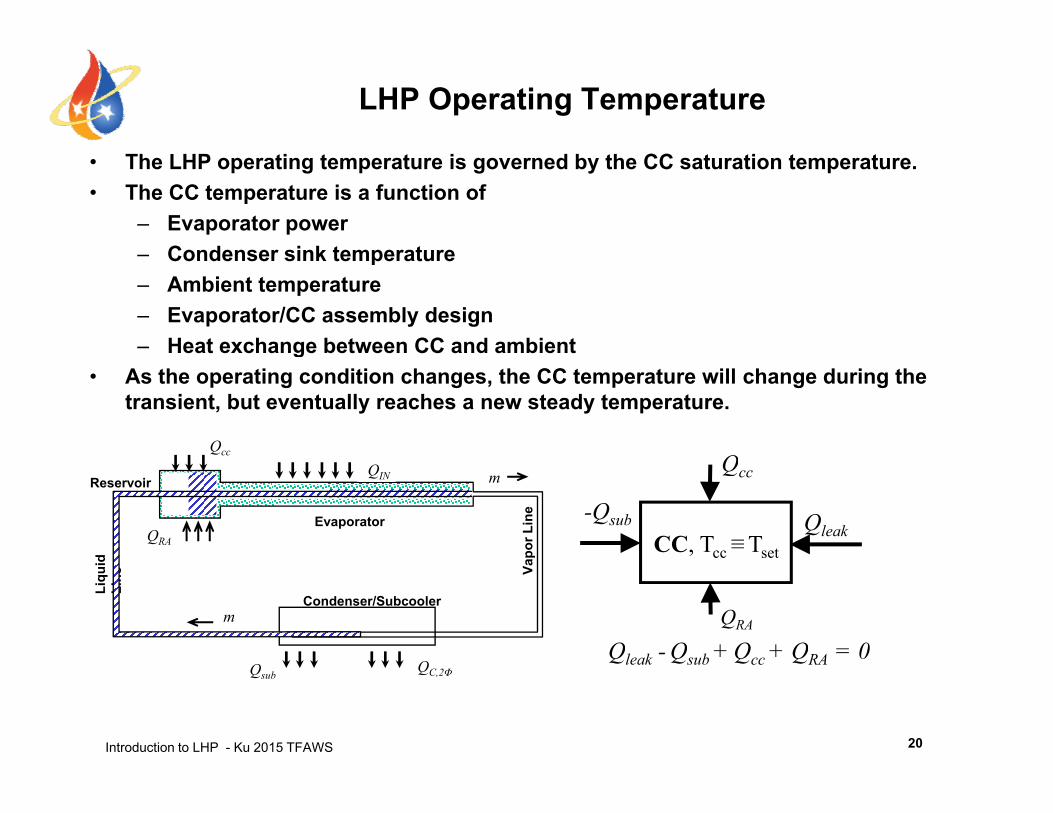
LHP Operating Temperature
• The LHP operating temperature is governed by the CC saturation temperature.• The CC temperature is a function of
– Evaporator powerCondenser sink temperature– Condenser sink temperature
– Ambient temperature– Evaporator/CC assembly design– Heat exchange between CC and ambient
Qcc
g• As the operating condition changes, the CC temperature will change during the
transient, but eventually reaches a new steady temperature.
Q
apor
Lin
e
d
Evaporator
ReservoirQIN m
QRA
-Qsub QleakCC, Tcc ≡Tset
Qcc
QRA
Condenser/Subcooler
Va
Liqu
idLi
ne
Q
m
Qleak - Qsub + Qcc + QRA = 0
Introduction to LHP - Ku 2015 TFAWS
Qsub QC,2Φ
20
Qleak Qsub Qcc QRA
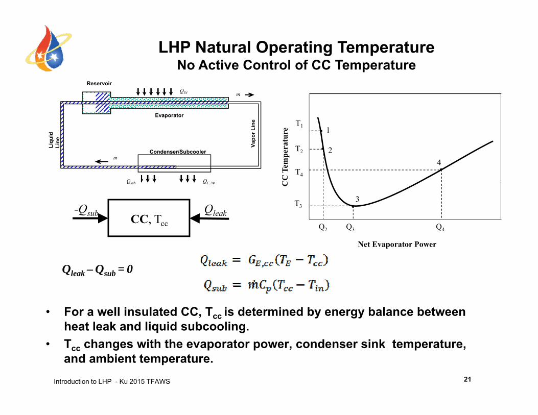
LHP Natural Operating TemperatureNo Active Control of CC Temperature
e
T1 1Line
Evaporator
ReservoirQIN m
CC
Tem
pera
ture
T2
T4
1
24
Condenser/Subcooler
Vapo
r L
Liqu
id
Line
m
-Qsub QleakCC, Tcc
C
T3
Q2 Q3 Q4
3
QC,2ΦQsub
Qleak – Qsub = 0
Net Evaporator Power
• For a well insulated CC, Tcc is determined by energy balance between heat leak and liquid subcooling.
Introduction to LHP - Ku 2015 TFAWS
• Tcc changes with the evaporator power, condenser sink temperature, and ambient temperature.
21
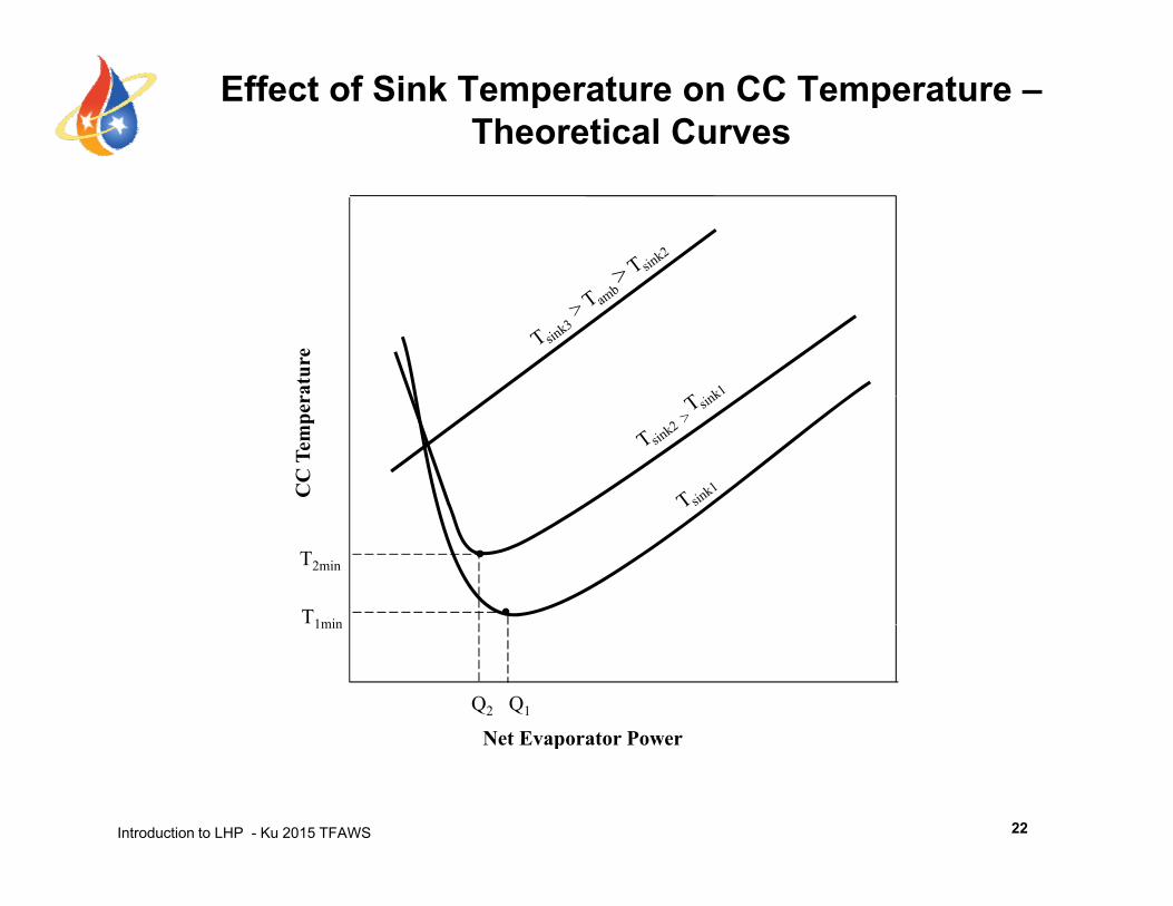
Effect of Sink Temperature on CC Temperature –Theoretical Curves
ratu
reC
C T
empe
r
T2min
T1min
Net Evaporator Power
Q2 Q1
1min
Introduction to LHP - Ku 2015 TFAWS
Net Evaporator Power
22
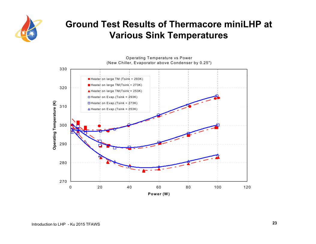
Ground Test Results of Thermacore miniLHP at Various Sink Temperatures
Operating Temperature vs Power (New Chiller, Evaporator above Condenser by 0.25")
330
310
320
(K)
Heater on large TM (Tsink = 293K)
Heater on large TM(Tsink = 273K)
Heater on large TM(Tsink = 253K)
Heater on Evap.(Tsink = 293K)
Heater on Evap.(Tsink = 273K)
300
310
ting
Tem
pera
ture
Heater on Evap.(Tsink = 253K)
280
290
Ope
rat
2700 20 40 60 80 100 120
Power (W )
Introduction to LHP - Ku 2015 TFAWS 23
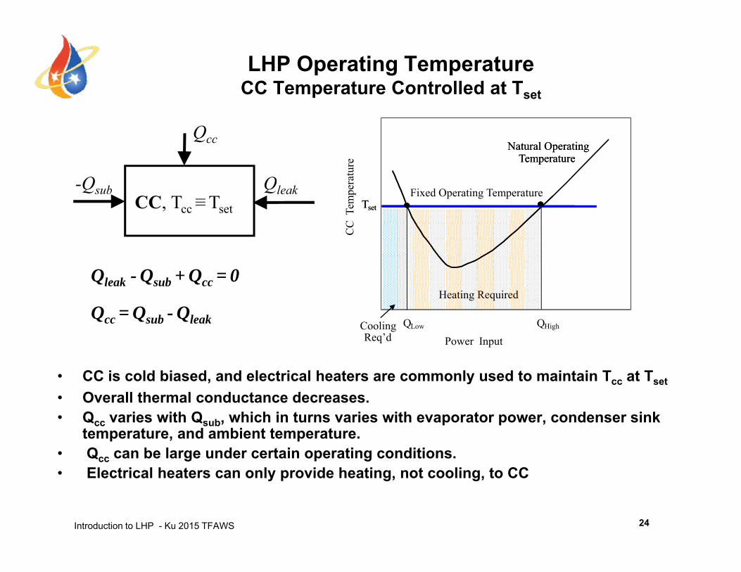
LHP Operating TemperatureCC Temperature Controlled at Tset
atur
e
Natural Operating Temperature
Natural Operating Temperature
Q Q
Qcc
CC
Tem
pera
Fixed Operating TemperatureTsetTset
-Qsub QleakCC, Tcc≡Tset
C li Q Q
Heating Required
Qcc = Qsub - Qleak
Qleak - Qsub + Qcc = 0
• CC is cold biased, and electrical heaters are commonly used to maintain Tcc at Tset
O ll th l d t d
Power InputCooling Req’d
QLow QHighQcc Qsub Qleak
• Overall thermal conductance decreases.• Qcc varies with Qsub, which in turns varies with evaporator power, condenser sink
temperature, and ambient temperature.• Qcc can be large under certain operating conditions.
Introduction to LHP - Ku 2015 TFAWS
• Electrical heaters can only provide heating, not cooling, to CC
24
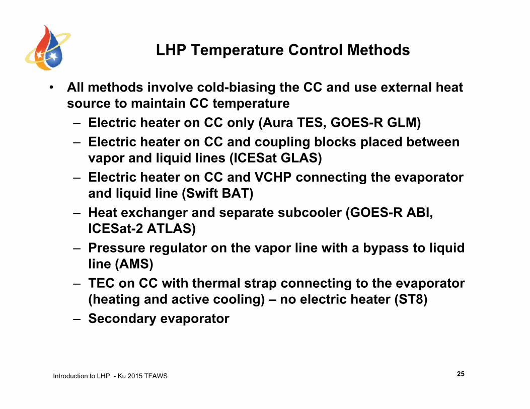
LHP Temperature Control Methods
• All methods involve cold-biasing the CC and use external heat source to maintain CC temperature– Electric heater on CC only (Aura TES, GOES-R GLM)y ( , )– Electric heater on CC and coupling blocks placed between
vapor and liquid lines (ICESat GLAS)– Electric heater on CC and VCHP connecting the evaporatorElectric heater on CC and VCHP connecting the evaporator
and liquid line (Swift BAT)– Heat exchanger and separate subcooler (GOES-R ABI,
ICESat-2 ATLAS)ICESat-2 ATLAS)– Pressure regulator on the vapor line with a bypass to liquid
line (AMS)TEC on CC with thermal strap connecting to the evaporator– TEC on CC with thermal strap connecting to the evaporator (heating and active cooling) – no electric heater (ST8)
– Secondary evaporator
Introduction to LHP - Ku 2015 TFAWS 25
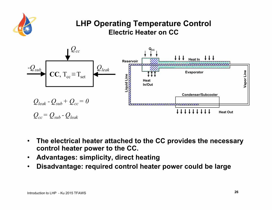
LHP Operating Temperature ControlElectric Heater on CC
Reservoir Heat In
QCC
Q Q
Qcc
Vapo
r Lin
e
Liqu
id L
ine
Evaporator
Heat In/Out
-Qsub QleakCC, Tcc≡Tset
Condenser/Subcooler
L
Heat OutQcc = Qsub - Qleak
Qleak - Qsub + Qcc = 0
• The electrical heater attached to the CC provides the necessary
Qcc Qsub Qleak
control heater power to the CC.• Advantages: simplicity, direct heating• Disadvantage: required control heater power could be large
Introduction to LHP - Ku 2015 TFAWS 26
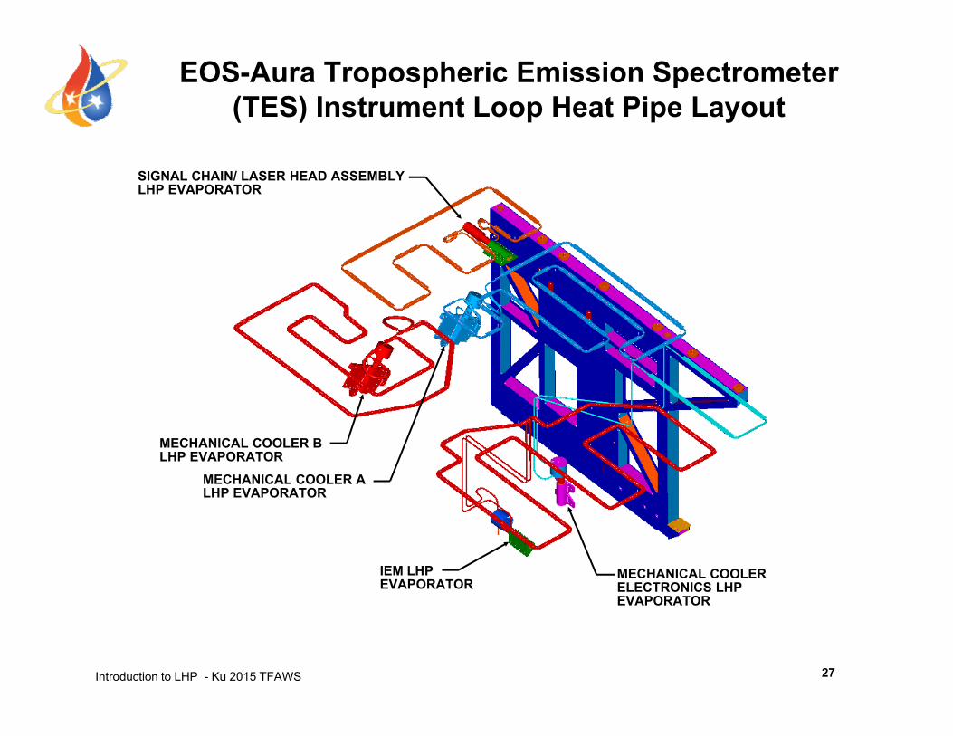
EOS-Aura Tropospheric Emission Spectrometer (TES) Instrument Loop Heat Pipe Layout
SIGNAL CHAIN/ LASER HEAD ASSEMBLYLHP EVAPORATOR
MECHANICAL COOLER BLHP EVAPORATOR
MECHANICAL COOLER ALHP EVAPORATOR
IEM LHP EVAPORATOR
MECHANICAL COOLER ELECTRONICS LHP EVAPORATOR
Introduction to LHP - Ku 2015 TFAWS
EVAPORATOR
27
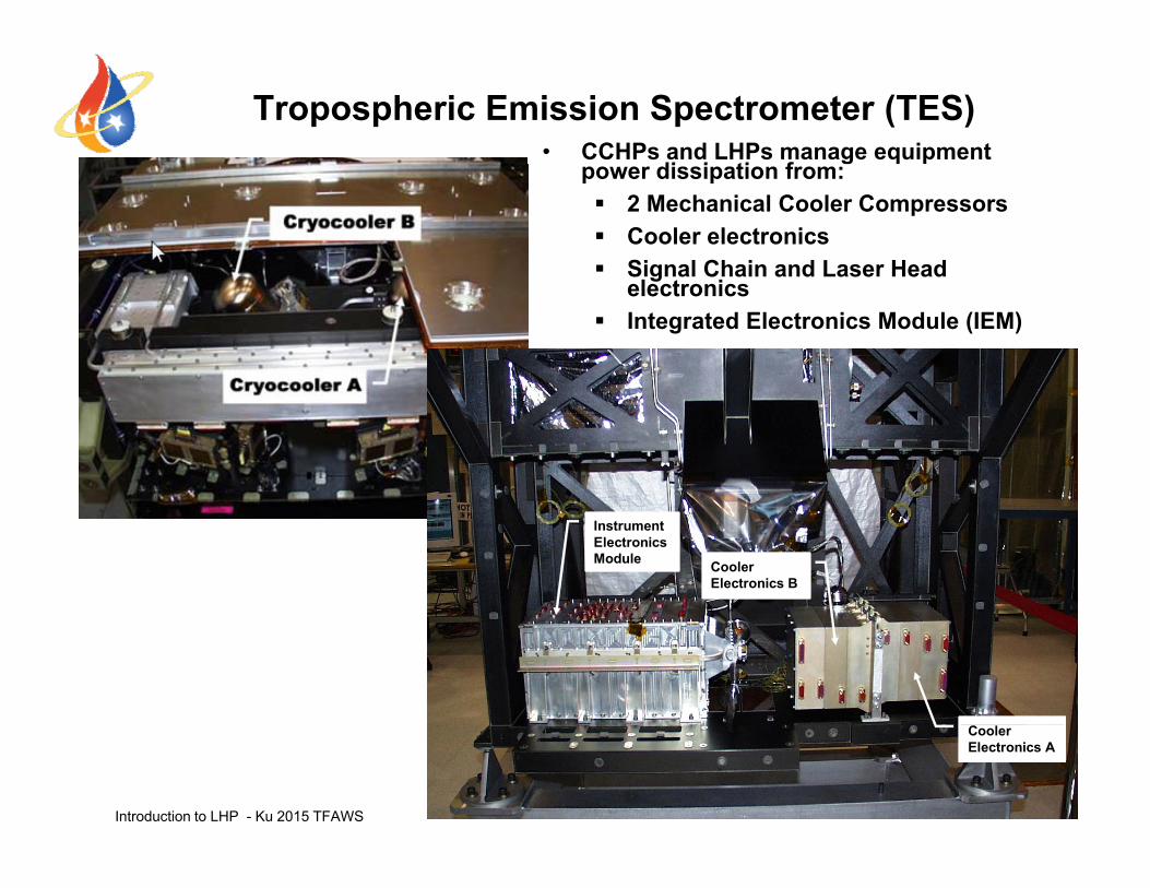
• CCHPs and LHPs manage equipment di i ti f
Tropospheric Emission Spectrometer (TES)power dissipation from: 2 Mechanical Cooler Compressors Cooler electronics Signal Chain and Laser HeadSignal Chain and Laser Head
electronics Integrated Electronics Module (IEM)
Cooler Electronics B
Instrument Electronics Module
Introduction to LHP - Ku 2015 TFAWS 28
Cooler Electronics A
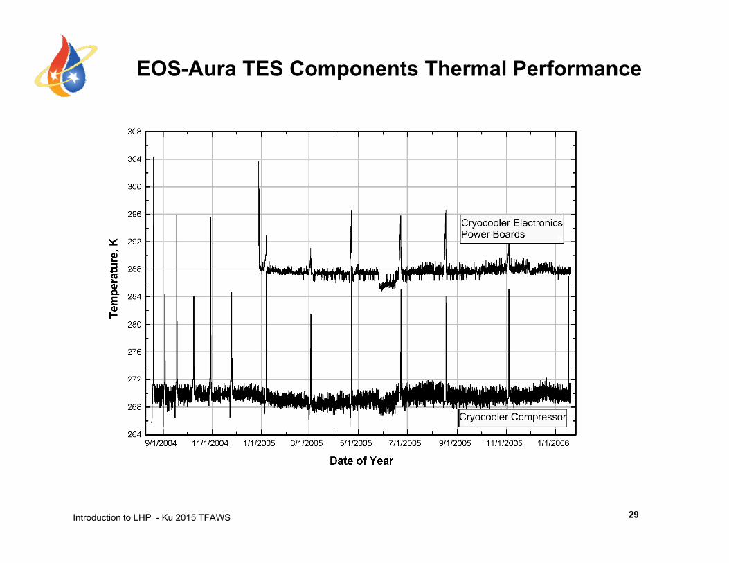
EOS-Aura TES Components Thermal Performance
Introduction to LHP - Ku 2015 TFAWS 29
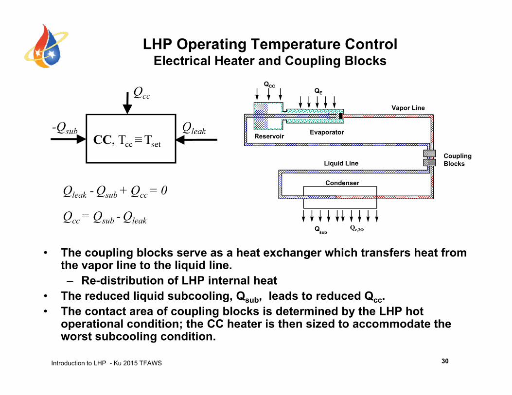
LHP Operating Temperature ControlElectrical Heater and Coupling Blocks
Vapor Line
QE
QCC
Q Q
Qcc
Liquid Line
EvaporatorReservoir
Coupling Blocks
-Qsub QleakCC, Tcc≡Tset
Condenser
Qcc = Qsub - Qleak
Qleak - Qsub + Qcc = 0
• The coupling blocks serve as a heat exchanger which transfers heat from the vapor line to the liquid line.
QsubQc,2Φ
Qcc Qsub Qleak
– Re-distribution of LHP internal heat• The reduced liquid subcooling, Qsub, leads to reduced Qcc.• The contact area of coupling blocks is determined by the LHP hot
operational condition; the CC heater is then sized to accommodate the
Introduction to LHP - Ku 2015 TFAWS
operational condition; the CC heater is then sized to accommodate the worst subcooling condition.
30
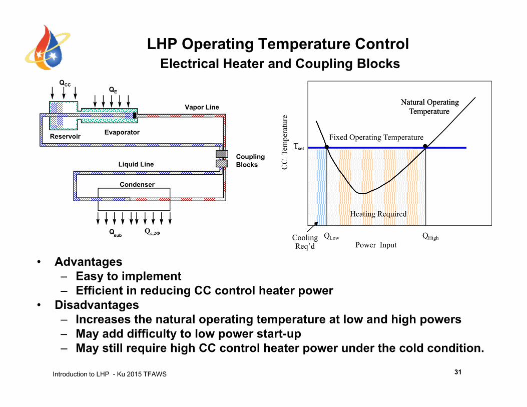
LHP Operating Temperature ControlElectrical Heater and Coupling Blocks
Vapor Line
QE
QCC
ture
Natural Operating Temperature
Natural Operating Temperature
Liquid Line
EvaporatorReservoir
Coupling Blocks C
C T
empe
rat
Fixed Operating TemperatureTsetTset
Condenser
Q
Heating Required
Q
• Advantages– Easy to implement
Qsub
Power InputCooling Req’d
QLow QHighQc,2Φ
y p– Efficient in reducing CC control heater power
• Disadvantages– Increases the natural operating temperature at low and high powers
May add difficulty to low power start up
Introduction to LHP - Ku 2015 TFAWS
– May add difficulty to low power start-up– May still require high CC control heater power under the cold condition.
31
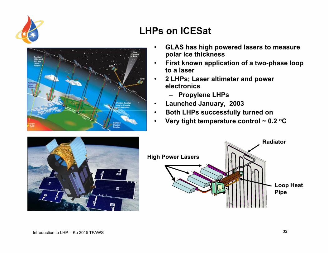
LHPs on ICESat• GLAS has high powered lasers to measure• GLAS has high powered lasers to measure
polar ice thickness• First known application of a two-phase loop
to a laser• 2 LHPs; Laser altimeter and power• 2 LHPs; Laser altimeter and power
electronics – Propylene LHPs
• Launched January, 2003B th LHP f ll t d• Both LHPs successfully turned on
• Very tight temperature control ~ 0.2 oC
Radiator
High Power Lasers
Radiator
Loop HeatPipe
Introduction to LHP - Ku 2015 TFAWS 32
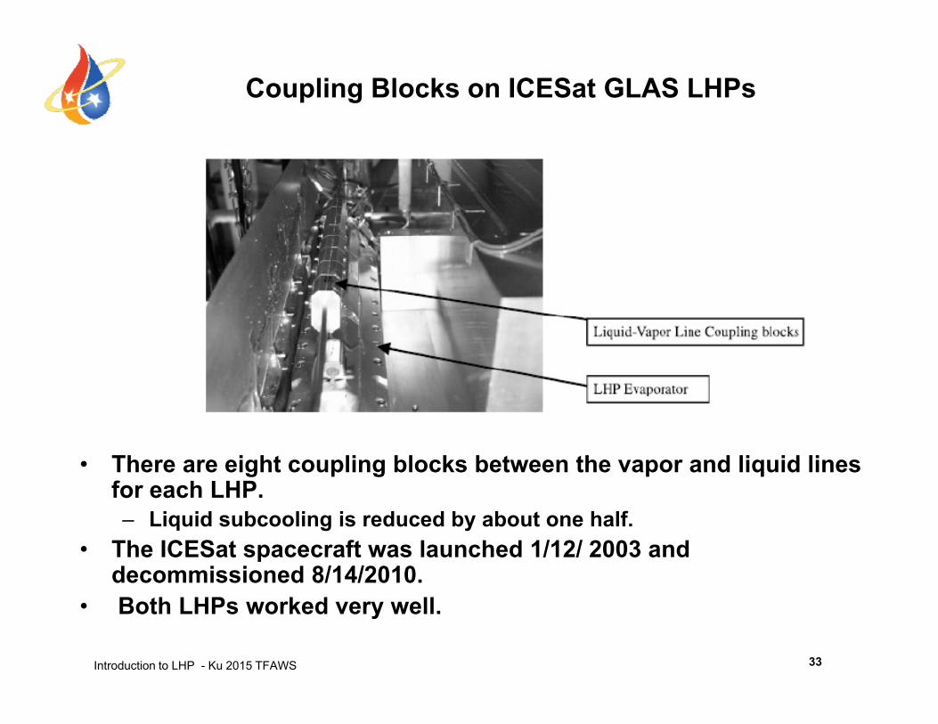
Coupling Blocks on ICESat GLAS LHPs
• There are eight coupling blocks between the vapor and liquid lines for each LHP.– Liquid subcooling is reduced by about one half.
• The ICESat spacecraft was launched 1/12/ 2003 and decommissioned 8/14/2010.
Introduction to LHP - Ku 2015 TFAWS
• Both LHPs worked very well.
33
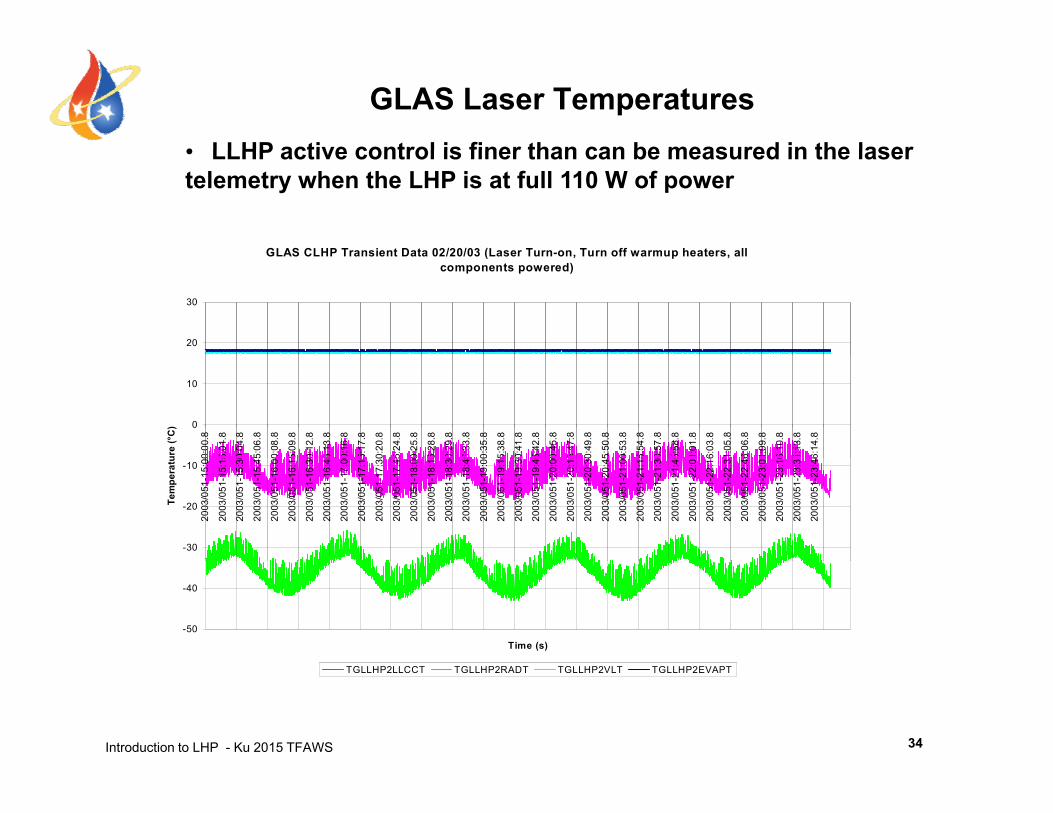
GLAS Laser Temperatures• LLHP active control is finer than can be measured in the laser
GLAS CLHP Transient Data 02/20/03 (Laser Turn-on Turn off warmup heaters all
• LLHP active control is finer than can be measured in the laser telemetry when the LHP is at full 110 W of power
GLAS CLHP Transient Data 02/20/03 (Laser Turn-on, Turn off warmup heaters, all components powered)
20
30
0
10
0:00
.8
5:01
.8
0:04
.8
5:06
.8
0:08
.8
5:09
.8
0:12
.8
5:13
.8
0:16
.8
5:17
.8
0:20
.8
5:24
.8
0:25
.8
5:28
.8
0:29
.8
5:33
.8
0:35
.8
5:38
.8
0:41
.8
5:42
.8
0:45
.8
5:47
.8
0:49
.8
5:50
.8
0:53
.8
5:54
.8
0:57
.8
5:58
.8
1:01
.8
6:03
.8
1:05
.8
6:06
.8
1:09
.8
6:10
.8
1:13
.8
6:14
.8
ure
(°C
)
-30
-20
-10
2003
/051
-15:
00
2003
/051
-15:
15
2003
/051
-15:
30
2003
/051
-15:
45
2003
/051
-16:
00
2003
/051
-16:
15
2003
/051
-16:
30
2003
/051
-16:
45
2003
/051
-17:
00
2003
/051
-17:
15
2003
/051
-17:
30
2003
/051
-17:
45
2003
/051
-18:
00
2003
/051
-18:
15
2003
/051
-18:
30
2003
/051
-18:
45
2003
/051
-19:
00
2003
/051
-19:
15
2003
/051
-19:
30
2003
/051
-19:
45
2003
/051
-20:
00
2003
/051
-20:
15
2003
/051
-20:
30
2003
/051
-20:
45
2003
/051
-21:
00
2003
/051
-21:
15
2003
/051
-21:
30
2003
/051
-21:
45
2003
/051
-22:
0
2003
/051
-22:
1 6
2003
/051
-22:
3
2003
/051
-22:
4 6
2003
/051
-23:
0
2003
/051
-23:
1 6
2003
/051
-23:
3
2003
/051
-23:
4 6
Tem
pera
tu
-50
-40
Time (s)
Introduction to LHP - Ku 2015 TFAWS
TGLLHP2LLCCT TGLLHP2RADT TGLLHP2VLT TGLLHP2EVAPT
34
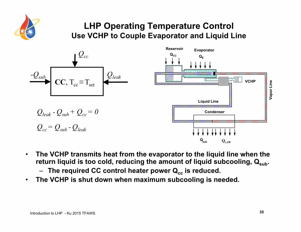
LHP Operating Temperature ControlUse VCHP to Couple Evaporator and Liquid Line
QE
EvaporatorReservoirQCC
Q Q
Qcc
Vapo
r Lin
e
Liquid Line
VCHP-Qsub Qleak
CC, Tcc≡Tset
Condenser
Liquid Line
Qcc = Qsub - Qleak
Qleak - Qsub + Qcc = 0
• The VCHP transmits heat from the evaporator to the liquid line when the t li id i t ld d i th t f li id b li Q
Qsub
Qcc Qsub Qleak
Qc,2Φ
return liquid is too cold, reducing the amount of liquid subcooling, Qsub.– The required CC control heater power Qcc is reduced.
• The VCHP is shut down when maximum subcooling is needed.
Introduction to LHP - Ku 2015 TFAWS 35
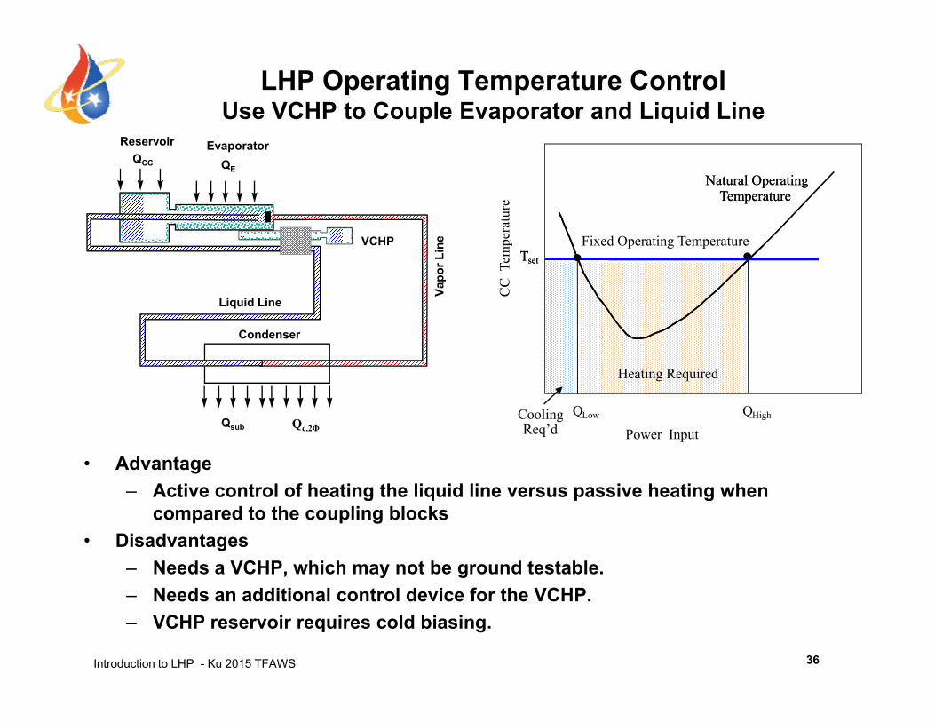
LHP Operating Temperature ControlUse VCHP to Couple Evaporator and Liquid Line
atur
e
Natural Operating Temperature
Natural Operating Temperature
QE
EvaporatorReservoirQCC
CC
Tem
pera
Fixed Operating TemperatureTsetTset
Vapo
r Lin
e
Liquid Line
VCHP
Q Q
Heating Required
Condenser
• Advantage– Active control of heating the liquid line versus passive heating when
Power InputCooling Req’d
QLow QHighQsub Qc,2Φ
g q p gcompared to the coupling blocks
• Disadvantages– Needs a VCHP, which may not be ground testable.
N d dditi l t l d i f th VCHP
Introduction to LHP - Ku 2015 TFAWS
– Needs an additional control device for the VCHP.– VCHP reservoir requires cold biasing.
36
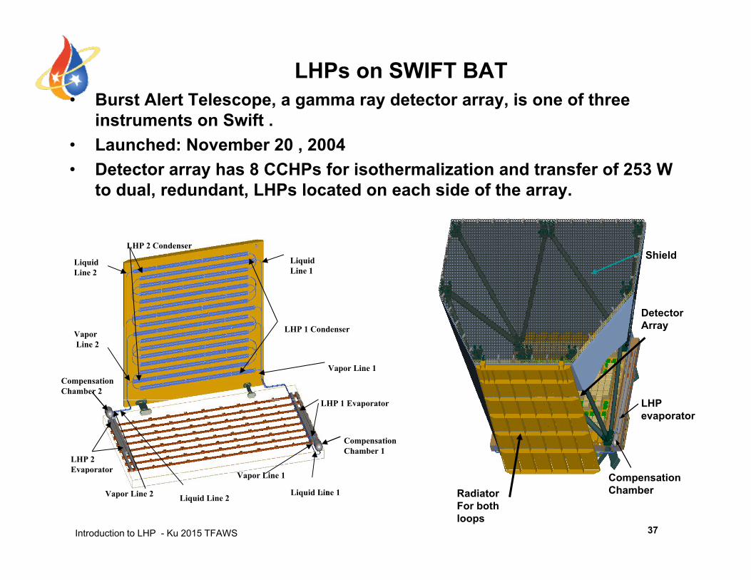
LHPs on SWIFT BAT• Burst Alert Telescope, a gamma ray detector array, is one of three p , g y y,
instruments on Swift .• Launched: November 20 , 2004 • Detector array has 8 CCHPs for isothermalization and transfer of 253 W
to dual, redundant, LHPs located on each side of the array.
ShieldLHP 2 Condenser
DetectorArray
Shield
LHP 1 C d
LiquidLine 2
LiquidLine 1
LHP
ArrayLHP 1 Condenser VaporLine 2
CompensationChamber 2
Vapor Line 1
LHP evaporator
CompensationChamber 1
LHP 1 Evaporator
LHP 2 Evaporator
V Li 1
Introduction to LHP - Ku 2015 TFAWS
CompensationChamberRadiator
For both loops
p
Liquid Line 1 Liquid Line 2 Vapor Line 2
Vapor Line 1
37
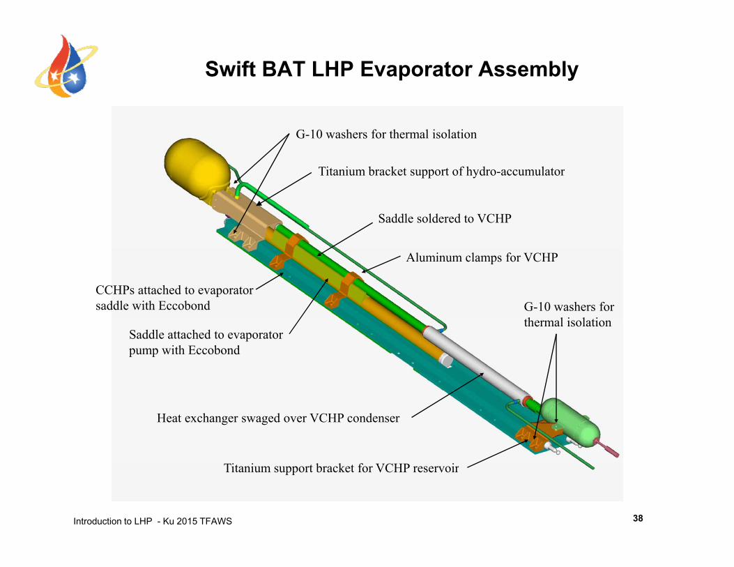
Swift BAT LHP Evaporator Assembly
Titanium bracket support of hydro-accumulator
G-10 washers for thermal isolation
pp y
Saddle soldered to VCHP
Aluminum clamps for VCHP
CCHPs attached to evaporatorsaddle with Eccobond G-10 washers for
th l i l tiSaddle attached to evaporatorpump with Eccobond
thermal isolation
Heat exchanger swaged over VCHP condenser
Introduction to LHP - Ku 2015 TFAWS 38
Titanium support bracket for VCHP reservoir
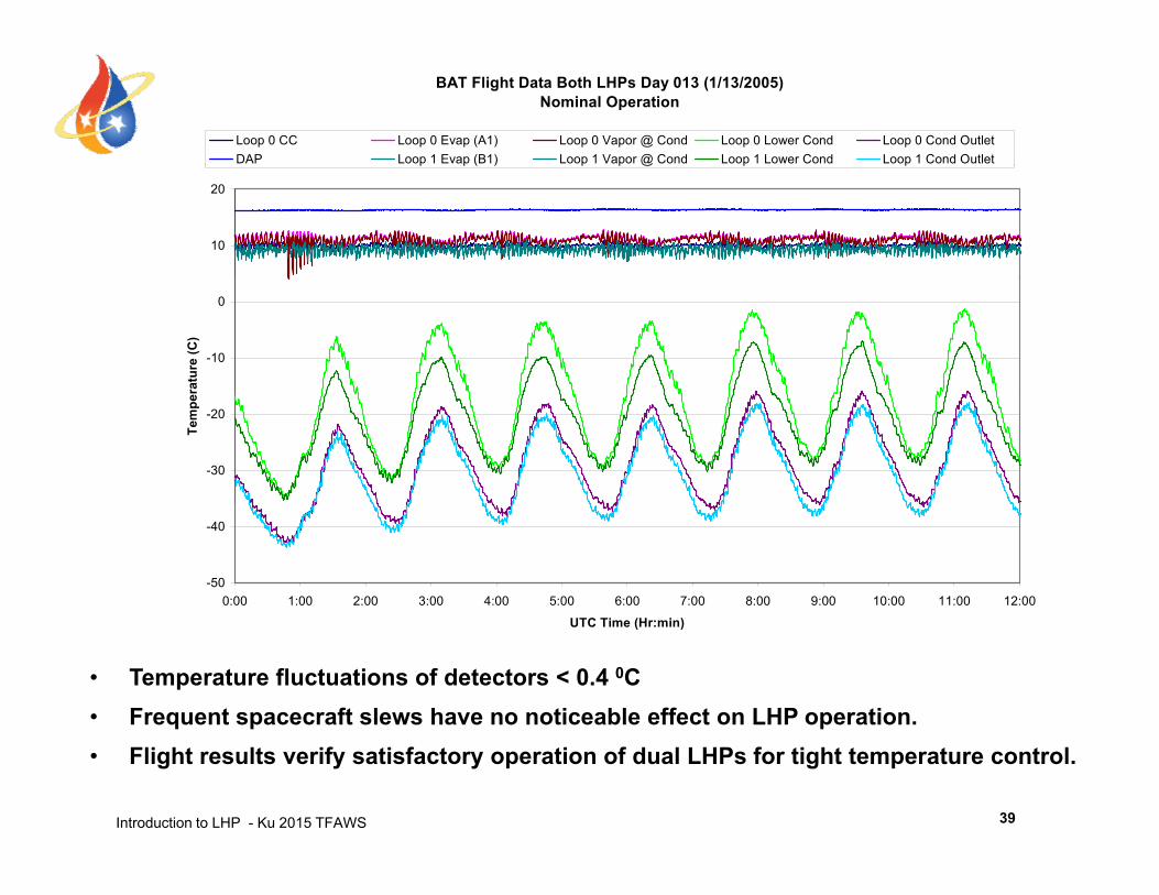
BAT Flight Data Both LHPs Day 013 (1/13/2005)Nominal Operation
Loop 0 CC Loop 0 Evap (A1) Loop 0 Vapor @ Cond Loop 0 Lower Cond Loop 0 Cond OutletDAP Loop 1 Evap (B1) Loop 1 Vapor @ Cond Loop 1 Lower Cond Loop 1 Cond Outlet
10
20
p p ( ) p p @ p p
-10
0
ratu
re (C
)
-30
-20
Tem
per
-50
-40
0:00 1:00 2:00 3:00 4:00 5:00 6:00 7:00 8:00 9:00 10:00 11:00 12:00
• Temperature fluctuations of detectors < 0.4 0C• Frequent spacecraft slews have no noticeable effect on LHP operation.
UTC Time (Hr:min)
Introduction to LHP - Ku 2015 TFAWS
• Flight results verify satisfactory operation of dual LHPs for tight temperature control.
39
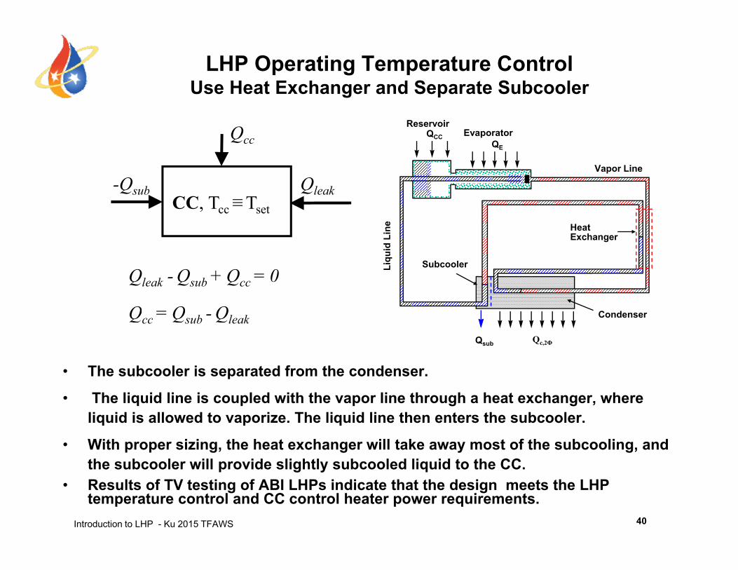
LHP Operating Temperature ControlUse Heat Exchanger and Separate Subcooler
Vapor Line
QE
EvaporatorReservoir
QCCQcc
id L
ine Heat
Exchanger
-Qsub QleakCC, Tcc≡Tset
Condenser
Liqu
i
Subcooler
Qcc = Qsub - Qleak
Qleak - Qsub + Qcc = 0
• The subcooler is separated from the condenser.
Th li id li i l d ith th li th h h t h h
Qsub
Qcc Qsub QleakQc,2Φ
• The liquid line is coupled with the vapor line through a heat exchanger, where liquid is allowed to vaporize. The liquid line then enters the subcooler.
• With proper sizing, the heat exchanger will take away most of the subcooling, and the subcooler will provide slightly subcooled liquid to the CC
Introduction to LHP - Ku 2015 TFAWS
the subcooler will provide slightly subcooled liquid to the CC.• Results of TV testing of ABI LHPs indicate that the design meets the LHP
temperature control and CC control heater power requirements.40

LHP Operating TemperatureUse Heat Exchanger and Separate Subcooler
atur
e
Natural Operating Temperature
Natural Operating Temperature
Vapor Line
QE
EvaporatorReservoir
QCC
CC
Tem
pera
Fixed Operating TemperatureTsetTset
uid
Line Heat
Exchanger
Q Q
Heating RequiredCondenser
Liqu Subcooler
• Advantages– The natural operating temperature will be closer to Tset for heat loads
Power InputCooling Req’d
QLow QHighQsub Qc,2Φ
p g p setbetween QLow and QHigh.
– The CC control heat power is reduced significantly.• Disadvantages
– Needs a separate subcooler
Introduction to LHP - Ku 2015 TFAWS
Needs a separate subcooler.– Needs a longer liquid line, which imposes a higher frictional pressure drop.
41
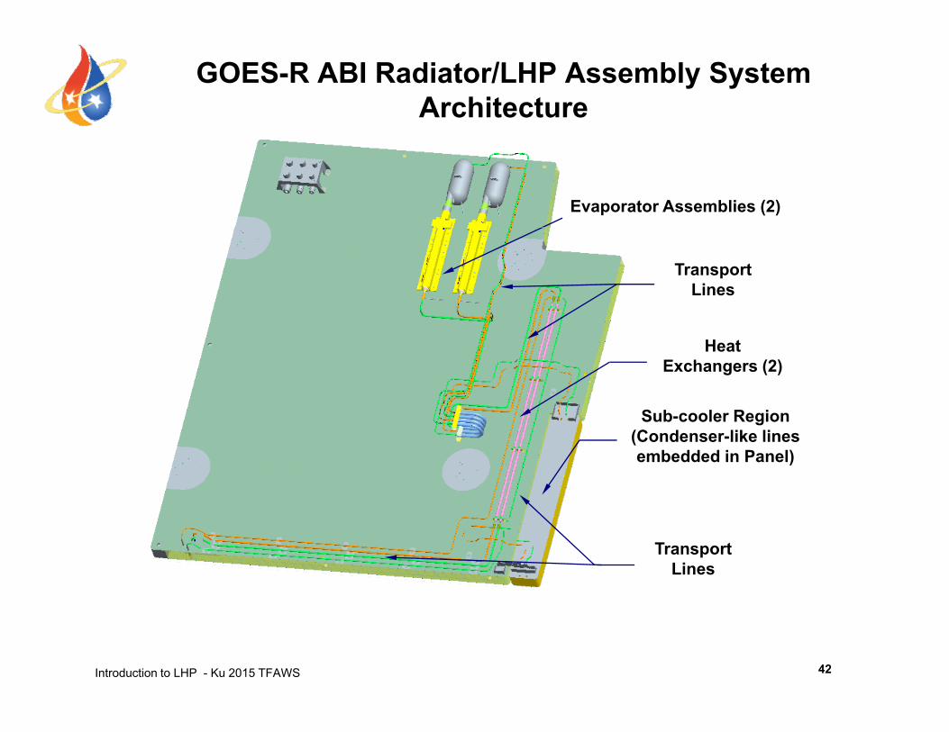
GOES-R ABI Radiator/LHP Assembly System Architecture
Evaporator Assemblies (2)
TransportLines
HeatExchangers (2)
S b l R iSub-cooler Region(Condenser-like linesembedded in Panel)
TransportLines
Introduction to LHP - Ku 2015 TFAWS 42
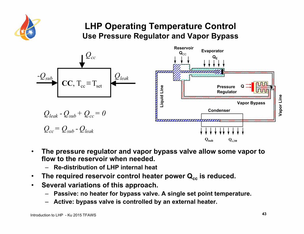
LHP Operating Temperature ControlUse Pressure Regulator and Vapor Bypass
QE
EvaporatorReservoirQCCQcc
Line
quid
Lin
e QPressure Regulator
Vapor Bypass
-Qsub QleakCC, Tcc≡Tset
Condenser
Vapo
r LLiq Vapor Bypass
Qcc = Qsub - Qleak
Qleak - Qsub + Qcc = 0
• The pressure regulator and vapor bypass valve allow some vapor to flow to the reservoir when needed.
Qsub
Qcc Qsub QleakQc,2Φ
– Re-distribution of LHP internal heat• The required reservoir control heater power Qcc is reduced.• Several variations of this approach.
Introduction to LHP - Ku 2015 TFAWS
– Passive: no heater for bypass valve. A single set point temperature.– Active: bypass valve is controlled by an external heater.
43
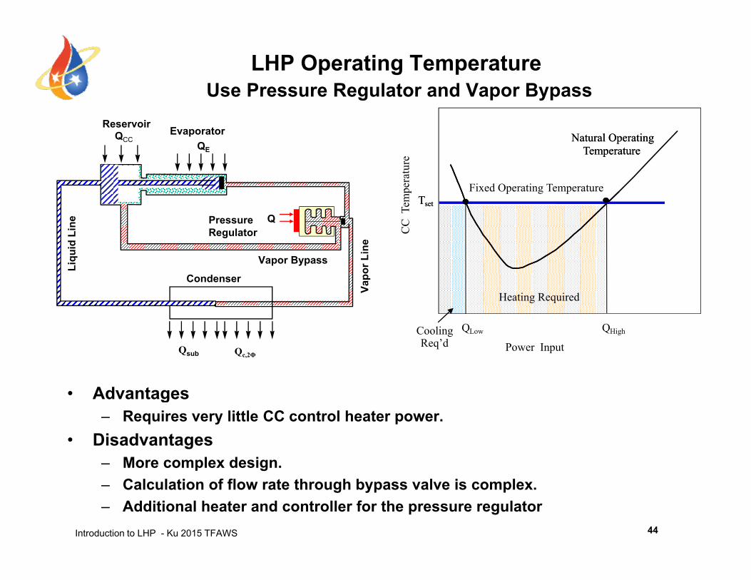
LHP Operating TemperatureUse Pressure Regulator and Vapor Bypass
ratu
re
Natural Operating Temperature
Natural Operating TemperatureQE
EvaporatorReservoirQCC
CC
Tem
per
Fixed Operating TemperatureTsetTset
ine
uid
Line QPressure
Regulator
C li Q Q
Heating RequiredCondenser
Vapo
r LLiqu Vapor Bypass
• Advantages
Power InputCooling Req’d
QLow QHigh
Qsub Qc,2Φ
g– Requires very little CC control heater power.
• Disadvantages– More complex design.
Introduction to LHP - Ku 2015 TFAWS
– Calculation of flow rate through bypass valve is complex. – Additional heater and controller for the pressure regulator
44
LHP Operating Temperature ControlUse Pressure Regulator and Vapor Bypass
• Passive bypass valve– Yamal 2000 spacecraft, launched in 2003
Payload temperature was controlled within 2K– Payload temperature was controlled within 2K.
• Active bypass valve– TerraSAR satellite– Ground tests demonstrated temperature control within
0.5K for heat load of 5W to 15W and condenser sink temperature between 233K and 308K.
– TerraSAR was launched in 2007. Thermal control system was functioning successfully.
Introduction to LHP - Ku 2015 TFAWS 45
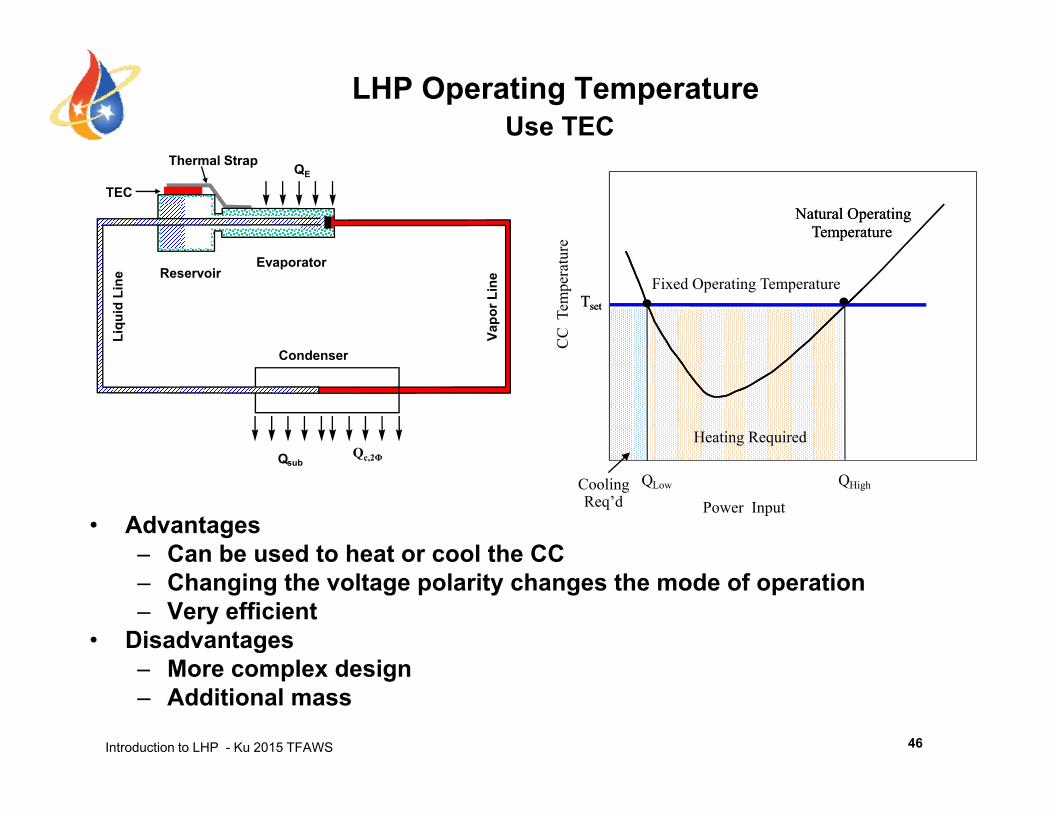
LHP Operating TemperatureUse TEC
Thermal Strap
TECQE
ure
Natural Operating Temperature
Natural Operating Temperature
Condenser
Vapo
r Lin
e
Liqu
id L
ine
EvaporatorReservoir
CC
Tem
pera
tu
Fixed Operating TemperatureTsetTset
Condenser
QHeating Required
Qc 2Φ
• Advantages– Can be used to heat or cool the CC
Qsub
Power InputCooling Req’d
QLow QHigh
Qc,2Φ
Can be used to heat or cool the CC– Changing the voltage polarity changes the mode of operation– Very efficient
• DisadvantagesM l d i
Introduction to LHP - Ku 2015 TFAWS
– More complex design– Additional mass
46

Schematic of ST 8 MLHP Use TECs and Coupling Blocks for CC Temperature Control
Heat InThermoelectric Converter
Radiator 1Heat O t
Instrument Simulator 1
Heat InHeat InThermoelectric Converter
Radiator 1Heat O t
Instrument Simulator 1
Evaporator 1CC 1Condenser 1
Radiator 1 Out
Evaporator 1CC 1Condenser 1
Radiator 1 Out
Vapor Line
Liquid Line
Coupling Block Flow Regulator
Vapor Line
Liquid Line
Coupling Block Flow Regulator
CC 2
Liquid Line
Heat In Instrument Simulator 2
CC 2
Liquid Line
Heat InHeat In Instrument Simulator 2
Evaporator 2
CC 2
Thermoelectric Converter Heat
Condenser 2
Radiator 2
Evaporator 2
CC 2
Thermoelectric Converter Heat
Condenser 2
Radiator 2
Condenser 2
Radiator 2
Introduction to LHP - Ku 2015 TFAWS
ConverterOut
ConverterOut
47
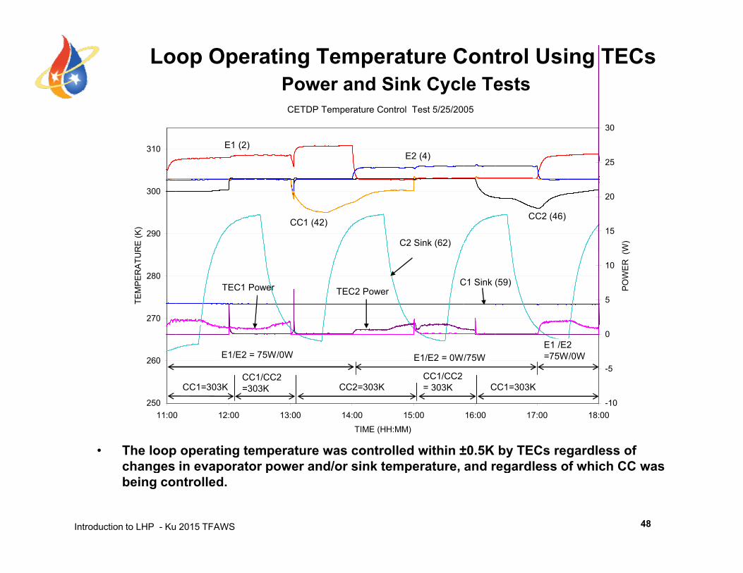
Loop Operating Temperature Control Using TECsPower and Sink Cycle Tests
CETDP T C l T /2 /200CETDP Temperature Control Test 5/25/2005
31025
30
E1 (2)E2 (4)
290
300
RE
(K) 15
20
W)C2 Sink (62)
CC1 (42)CC2 (46)
270
280
TEM
PER
ATU
R
5
10
POW
ER (
W
C1 Sink (59)TEC1 Power TEC2 Power
260-5
0
CC1=303K
E1/E2 = 75W/0W E1/E2 = 0W/75WE1 /E2=75W/0W
CC1/CC2=303K CC2=303K
CC1/CC2= 303K CC1=303K
25011:00 12:00 13:00 14:00 15:00 16:00 17:00 18:00
TIME (HH:MM)
-10
• The loop operating temperature was controlled within ±0.5K by TECs regardless of changes in evaporator power and/or sink temperature and regardless of which CC was
Introduction to LHP - Ku 2015 TFAWS
changes in evaporator power and/or sink temperature, and regardless of which CC was being controlled.
48
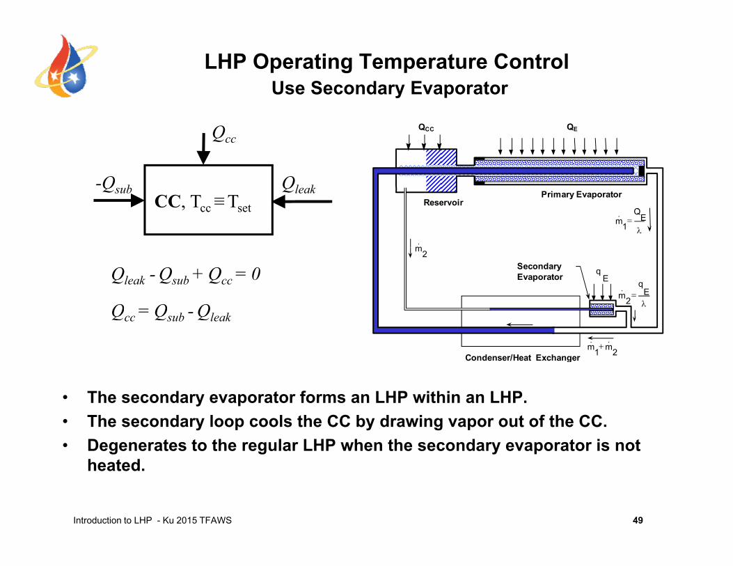
LHP Operating Temperature ControlUse Secondary Evaporator
QCC QEQcc
Primary EvaporatorReservoir
E
1
Qm
m
-Qsub QleakCC, Tcc≡Tset
Secondary Evaporator E
q
E
2
qm
2m
Qcc = Qsub - Qleak
Qleak - Qsub + Qcc = 0
Condenser/Heat Exchanger 21 mm
Qcc Qsub Qleak
• The secondary evaporator forms an LHP within an LHP.• The secondary loop cools the CC by drawing vapor out of the CC.• Degenerates to the regular LHP when the secondary evaporator is not
h t d
Introduction to LHP - Ku 2015 TFAWS 49
heated.
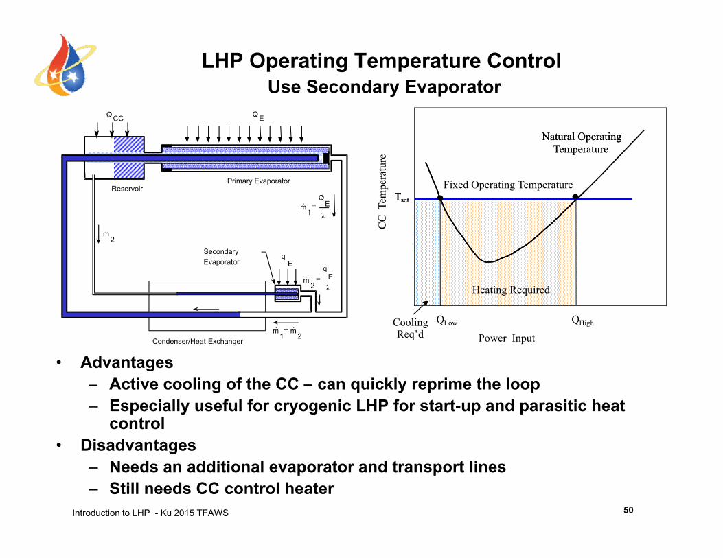
LHP Operating Temperature ControlUse Secondary Evaporator
atur
e
Natural Operating Temperature
Natural Operating Temperature
QCC QE
CC
Tem
pera
Fixed Operating TemperatureTsetTset
Primary EvaporatorReservoir
E
1
Qm
2m
Heating Required
Secondary Evaporator E
q
E
2
qm
• Advantages– Active cooling of the CC – can quickly reprime the loop
Power InputCooling Req’d
QLow QHigh
Condenser/Heat Exchanger21
mm
– Active cooling of the CC – can quickly reprime the loop– Especially useful for cryogenic LHP for start-up and parasitic heat
control• Disadvantages
Introduction to LHP - Ku 2015 TFAWS
– Needs an additional evaporator and transport lines– Still needs CC control heater
50
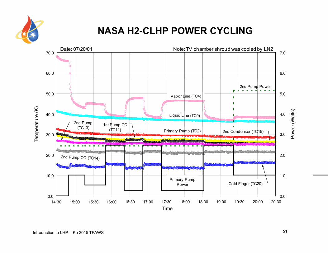
NASA H2-CLHP POWER CYCLING
60.0
70.0Date: 07/20/01 Note: TV chamber shroud was cooled by LN2
6.0
7.0
50.0
K)
5.0
s)
2nd Pump Power
30.0
40.0
Tem
pera
ture
(K
Primary Pump (TC2)
2nd Pump(TC13)
2nd Condenser (TC15)3.0
4.0
Pow
er (W
atts
1st Pump CC(TC11)
10 0
20.0
1 0
2.0
10.0
14:30 15:00 15:30 16:00 16:30 17:00 17:30 18:00 18:30
Cold Finger (TC20)
0.0
1.0
0.0
Primary PumpPower
19:00 19:30 20:00 20:30
Introduction to LHP - Ku 2015 TFAWS 51
Time
Outline
• From Heat Pipe to Loop Heat Pipe and Capillary Pumped Loop
• LHP Operating PrinciplesLHP Operating Principles• LHP Components Sizing and Fluid Inventory• LHP Operating Temperature Control• LHP Start-up and Shutdown• LHP Analytical Modeling• Recent LHP Technology Developments• Recent LHP Technology Developments• Summary
Introduction to LHP - Ku 2015 TFAWS 2
LHP Start-up
• LHP Start-up is a complex phenomenon.
• The primary wick must be wetted prior to start-up.
• The loop start-up behavior depends on initial conditions inside the evaporator.
f f– Vapor grooves on the outer surface of the primary wick• Liquid filled: superheat is required for nucleate boiling• Vapor presence: instant evaporation
– Liquid core on the inner surface of the primary wick• Liquid filled: low heat leak• Vapor presence: high heat leak
• A minimum power is required for start-up under certain conditions.
Introduction to LHP - Ku 2015 TFAWS 53
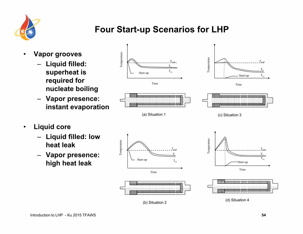
Four Start-up Scenarios for LHP
• Vapor grooves– Liquid filled:
superheat is
Tem
pera
ture
Te
TccStart up
Tamb
Tem
pera
ture
Te
Tamb
superheat is required for nucleate boiling
– Vapor presence:
Time
Start-up
Time
TccStart-up
p pinstant evaporation
• Liquid core
(a) Situation 1 (c) Situation 3
– Liquid filled: low heat leak
– Vapor presence: hi h h t l k
Tem
pera
ture
Te
TStart-up
Tamb
Tem
pera
ture
Te
Tcc
Tamb
St thigh heat leakTime
Tcc
Time
Start-up
Introduction to LHP - Ku 2015 TFAWS 54
(b) Situation 2 (d) Situation 4
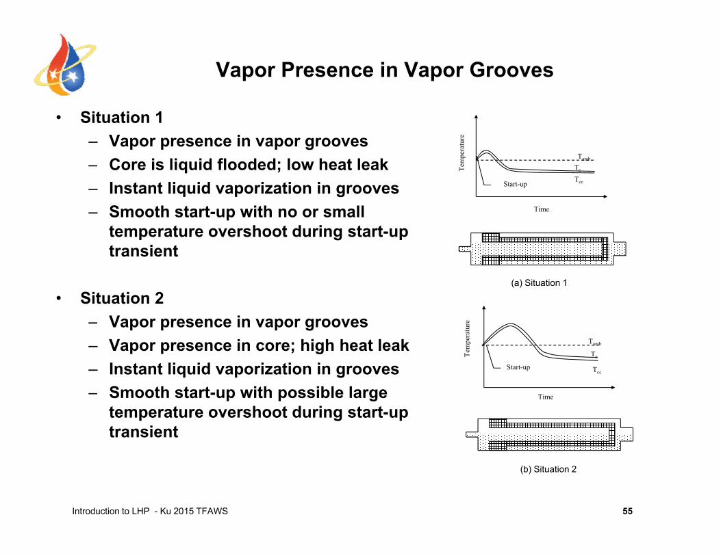
Vapor Presence in Vapor Grooves
• Situation 1– Vapor presence in vapor grooves– Core is liquid flooded; low heat leak Te
mpe
ratu
re
Te
Tambq– Instant liquid vaporization in grooves– Smooth start-up with no or small
temperature overshoot during start-up Time
TccStart-up
transient
• Situation 2(a) Situation 1
– Vapor presence in vapor grooves– Vapor presence in core; high heat leak– Instant liquid vaporization in grooves
Tem
pera
ture
Te
TccStart-up
Tamb
– Smooth start-up with possible large temperature overshoot during start-up transient
Time
Introduction to LHP - Ku 2015 TFAWS
(b) Situation 2
55
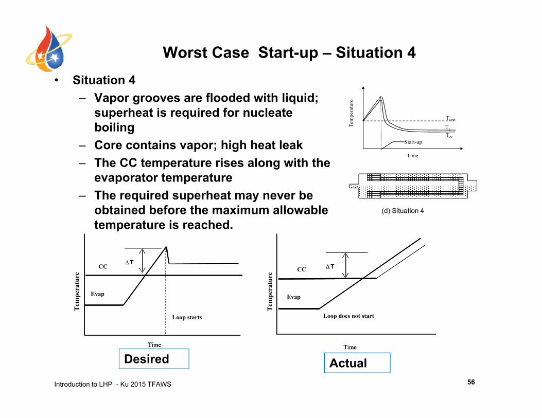
Worst Case Start-up – Situation 4 Sit ti 4• Situation 4– Vapor grooves are flooded with liquid;
superheat is required for nucleate boiling Te
mpe
ratu
re
Te
Tamb
boiling– Core contains vapor; high heat leak– The CC temperature rises along with the
evaporator temperature
Time
e
TccStart-up
p p– The required superheat may never be
obtained before the maximum allowable temperature is reached.
(d) Situation 4
CC Tra
ture
CCT
ratu
re
Evap
Loop does not start
Tem
per
Evap
Loop starts
Tem
per
Introduction to LHP - Ku 2015 TFAWS
TimeTimeTimeTime
Desired Actual56
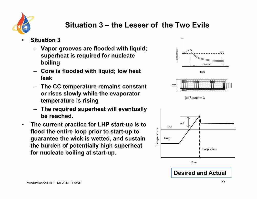
Situation 3 – the Lesser of the Two Evils
• Situation 3– Vapor grooves are flooded with liquid;
superheat is required for nucleate boiling Te
mpe
ratu
re
Te
Tamb
boiling– Core is flooded with liquid; low heat
leak– The CC temperature remains constant
Time
TccStart-up
– The CC temperature remains constant or rises slowly while the evaporator temperature is rising
– The required superheat will eventually
(c) Situation 3
ybe reached.
• The current practice for LHP start-up is to flood the entire loop prior to start-up to
t th i k i tt d d t i
CC
E
T
erat
ure
guarantee the wick is wetted, and sustain the burden of potentially high superheat for nucleate boiling at start-up.
Time
Evap
Loop starts
TimeT
empe
Introduction to LHP - Ku 2015 TFAWS
TimeTime
Desired and Actual 57
High and Low Power Start-up
• With high power to the evaporator, liquid in the vapor grooves can be vaporized quickly regardless of the initial two-phase status in the grooves and the evaporator core.– The required superheat, if any, can be achieved in a short time.– Within the short time, the total heat leak is small.
• With low power to the evaporator, start-up could be problematic.– Under situation 4, the required superheat for nucleate boiling
may never be achieved.may never be achieved.– After the loop starts, a steady state may not be established
within the allowable temperature limit at low powers due to a high heat leak from evaporator to CC if the core contains vapor.high heat leak from evaporator to CC if the core contains vapor.
Introduction to LHP - Ku 2015 TFAWS 58
I di ti f th i ti f l t t
Some Examples of Start-up Tests
• Indication of the inception of loop start-up:– Sudden sharp increase of the vapor line temperature to the
CC saturation temperature– Sudden sharp decrease of the liquid line temperature
• Successful start-upp– The CC temperature approaches a SS– The vapor line temperature approaches a SS (same as or
close to the CC temperature)close to the CC temperature) – The evaporator temperature approaches a SS (slightly
higher than the CC temperature)
• Results of some start-up tests under various conditions follow.
Introduction to LHP - Ku 2015 TFAWS 59
GLAS LHP Breadboard Start-up(Evaporator core is liquid-filled)
Sit ti 3 t t12/1/97GLAS LHP Start-Up
100 watts, No Controlling, Chiller@0°C, Radiator in Horizontal Position
CompCham(TC2) Evaporator(TC10) VapLine(TC22) LiqLine(TC52) Cart1
Situation 3 start-up
295
300
100
120
power
290
ture
(ºC
) 80
r (W
)
evapcomp cham
280
285
Tem
pera
t
40
60
Pow
er
liq linevap line
270
275
9:15 9:30 9:45 10:00 10:15 10:300
20
vap line
Introduction to LHP - Ku 2015 TFAWS
Time(Hours)
60
GLAS LHP Breadboard Start-up( Vapor present in evaporator core)
Sit ti 4 t t 100W
GLAS LHP Start-Up100 watts, No Controlling, Chiller@0°C, Radiator in Vertical Position
C Ch (TC2) E t (TC10) V Li (TC22) Li Li (TC52) C t1
Situation 4 start-up: 100W
300
305
100
120
CompCham(TC2) Evaporator(TC10) VapLine(TC22) LiqLine(TC52) Cart1
power
290
295
re (K
)
80
100
W)
evap
comp cham
280
285
Tem
pera
tur
40
60
Pow
er (W
270
275
9 5 9 7 9 9 10 1 10 3 10 5 10 7 10 90
20
vap line
liq line
Introduction to LHP - Ku 2015 TFAWS
9.5 9.7 9.9 10.1 10.3 10.5 10.7 10.9
Time(Hours)
61
GLAS LHP Breadboard Start-up( Vapor present in evaporator core)
GLAS LHP Testing
Situation 4 start-up: 20W
26Nov1997
320 25
Evaporator CompCham
300
310
15
20Evaporator
Power
CompCham
290 10
LiqLine
270
280
9:00 9:30 10:00 10:30 11:00 11:30 12:00 12:300
5VapLine
Introduction to LHP - Ku 2015 TFAWS
9:00 9:30 10:00 10:30 11:00 11:30 12:00 12:30
Time
62
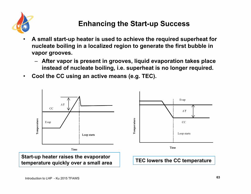
Enhancing the Start-up Success
• A small start-up heater is used to achieve the required superheat for nucleate boiling in a localized region to generate the first bubble in vapor grooves.
After vapor is present in grooves liquid evaporation takes place– After vapor is present in grooves, liquid evaporation takes place instead of nucleate boiling, i.e. superheat is no longer required.
• Cool the CC using an active means (e.g. TEC).
Evap
CCT
Loop starts
CC
T
Tem
pera
ture
Evap
CC
Tem
pera
ture
Time
Loop starts
Time
T
Time
Loop starts
Time
Loop startsT
Start-up heater raises the evaporator
Introduction to LHP - Ku 2015 TFAWS
TEC lowers the CC temperatureStart up heater raises the evaporator temperature quickly over a small area
63
LHP Shutdown
• Some instrument operation requires LHP to shutdown for a period of time.• LHP can continue to pump fluid if the evaporator temperature is higher
than the CC temperature.• Requirements for LHP shutdown
– No net heat load to evaporator– CC temperature is higher than evaporator temperature
• Heating the CC is the only viable method• When the CC temperature is higher than the evaporator temperature, fluid
flow stops.– Loop will not restart as long as there is no net heat load to evaporator. – Loop may restart if the evaporator continues to receive net heat load
and its temperature rises above the CC temperature.T t th t th l d t b it i i ll bl• To guarantee that the payload stays above its minimum allowable temperature, the CC temperature control can be set slightly above that value during loop shutdown.
Introduction to LHP - Ku 2015 TFAWS 64

Outline
• From Heat Pipe to Loop Heat Pipe and Capillary Pumped Loop
• LHP Operating PrinciplesLHP Operating Principles• LHP Components Sizing and Fluid Inventory• LHP Operating Temperature Control• LHP Start-up and Shutdown• LHP Analytical Modeling• Recent LHP Technology Developments• Recent LHP Technology Developments• Summary
Introduction to LHP - Ku 2015 TFAWS 2
Analytical Modeling of LHP
• SINDA/Fluint can be used to model LHP operation.– CAPIL connector and CAPPMP macro to model wick– Phase suction option to model two-phase heat transferPhase suction option to model two phase heat transfer– Tedious and time-consuming to build the detailed LHP model– Run time could be an issue
• Under NASA SBIR and the ST 8 Project, TTH Research Inc. has developed an LHP model specifically for the simulation LHP operationoperation.
Introduction to LHP - Ku 2015 TFAWS 66
NASA LHP Analytical Model
• Developed by TTH Research, Inc. under NASA SBIR Project in 2002.
• The objective was to develop an analytical model to simulate LHP steady state and transient behaviors– based upon physical laws and verified by test data– efficient and stable solutions– easy to use by thermal analysts (non-experts)– accurate and detailed predictions for LHP researchers
(experts)(experts)– Can be used as a stand-alone model for LHP design, or a
subroutine to general thermal analyzer (e.g. SINDA/Fluint)
• Additional funding for modeling the secondary wick was provided by DOD and the ST8 project in 2005.
Introduction to LHP - Ku 2015 TFAWS 67
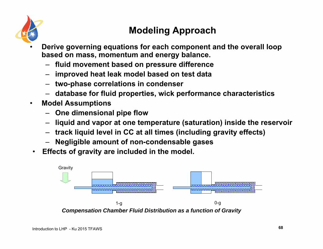
Modeling Approach• Derive governing equations for each component and the overall loop• Derive governing equations for each component and the overall loop
based on mass, momentum and energy balance. – fluid movement based on pressure difference– improved heat leak model based on test datap– two-phase correlations in condenser – database for fluid properties, wick performance characteristics
• Model Assumptions– One dimensional pipe flow– liquid and vapor at one temperature (saturation) inside the reservoir– track liquid level in CC at all times (including gravity effects)
N li ibl t f d bl– Negligible amount of non-condensable gases• Effects of gravity are included in the model.
Gravity
1 g 0-g
Introduction to LHP - Ku 2015 TFAWS
1-g 0-g
Compensation Chamber Fluid Distribution as a function of Gravity
68
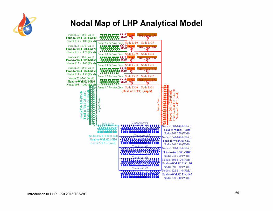
Nodal Map of LHP Analytical ModelFluid-to-Wall G171-G180
510 505 (Pump #5)CC #5WallFluid-to-Wall G171-G180
510 505 (Pump #5)CC #5Wall
Nodes 371 380 (Wall)Fluid-to-Wall G171-G180
510 505 (Pump #5)CC #5Wall
Fluid-to-Wall G161-G170
Fluid-to-Wall G151-G160
Pump #3 Return Line
Pump #4 Return Line
Pump #5 Return Line
508
509
503 (Pump #3)
504 (Pump #4)
CC #3Wall
CC #4WallFluid-to-Wall G161-G170
Fluid-to-Wall G151-G160508
509
503 (Pump #3)
504 (Pump #4)
CC #3Wall
CC #4Wall
Nodes 1151-1160 (Fluid)
Nodes 351 360 (Wall)
Nodes 1161-1170 (Fluid)
Nodes 361 370 (Wall)Nodes 1171-1180 (Fluid)
Node 1308
Node 1309
Node 1310
Node 1303
Node 1304
Node 1305
Fluid-to-Wall G161-G170
Fluid-to-Wall G151-G160508
509
503 (Pump #3)
504 (Pump #4)
CC #3Wall
CC #4Wall
d)l) 0
Fluid-to-Wall G141-G150
Fluid-to-Wall G51-G60
Pump #1 Return Line
Pump #2 Return Line
Pump #3 Return Line
(Fluid in CC #1) (Vapor)
506
507
CC #1Wall 501 (Pump #1)
502 (Pump #2)CC #2WallFluid-to-Wall G141-G150
Fluid-to-Wall G51-G60
(Fluid in CC #1) (Vapor)
506
507
CC #1Wall 501 (Pump #1)
502 (Pump #2)CC #2Wall
20d) )
Nodes 1051-1060 (Fluid)
Nodes 251-260 (Wall)Nodes 1141-1150 (Fluid)
Nodes 341 350 (Wall)
Node 1306
Node 1307
Node 1308
Node 1301
Node 1302
Node 1303
d)d)l) 0
Fluid-to-Wall G141-G150
Fluid-to-Wall G51-G60
(Fluid in CC #1) (Vapor)
506
507
CC #1Wall 501 (Pump #1)
502 (Pump #2)CC #2Wall
Nod
es 1
201-
1220
(Flu
id
Liqu
id L
ine
Nod
es 2
31- 2
50 (W
all
Flui
d-to
-Wal
l G31
-G5
Vapo
r Lin
e
( ) ( p )
Liqu
id L
ine
Flui
d-to
--
( ) ( p )
--W
all G
201-
G22
luid
to
Nod
es 1
031-
1050
(Flu
i d
Nod
es 4
01-4
20 (W
all)
Nod
es 1
201-
1220
(Flu
idN
odes
120
1-12
20 (F
luid
Nod
es 2
31- 2
50 (W
all
Flui
d-to
-Wal
l G31
-G5
( ) ( p )
N
Fluid-to-Wall G1-G20
Fluid-to-Wall G61-G80
Condenser #2
Condenser #1
C d #3
Fluid-to-Wall G21-G30
F
Fluid-to-Wall G1-G20
Fluid-to-Wall G61-G80Fluid-to-Wall G21-G30
F Fl
Nodes 1001-1020 (Fluid)
Nodes 201 220 (Wall)Nodes 1061-1080 (Fluid)
Nodes 261 280 (Wall)
Nodes 1021-1030 (Fluid)
Nodes 221 230 (Wall)
Subcooler
N NNN
Fluid-to-Wall G1-G20
Fluid-to-Wall G61-G80Fluid-to-Wall G21-G30
F
Fluid-to-Wall G1-G20
Fluid-to-Wall G81-G100
Fluid-to-Wall G101-G120
Condenser #3
Condenser #4
Condenser #5
Fluid-to-Wall G81-G100
Fluid-to-Wall G101-G120
( )Nodes 1081-1100 (Fluid)
Nodes 281 300 (Wall)Nodes 1101-1120 (Fluid)
Nodes 301 320 (Wall)Nodes 1121-1140 (Fluid)
Fluid-to-Wall G81-G100
Fluid-to-Wall G101-G120
Introduction to LHP - Ku 2015 TFAWS
Fluid-to-Wall G121-G140Fluid-to-Wall G121-G140( )
Nodes 321 340 (Wall)Fluid-to-Wall G121-G140
69
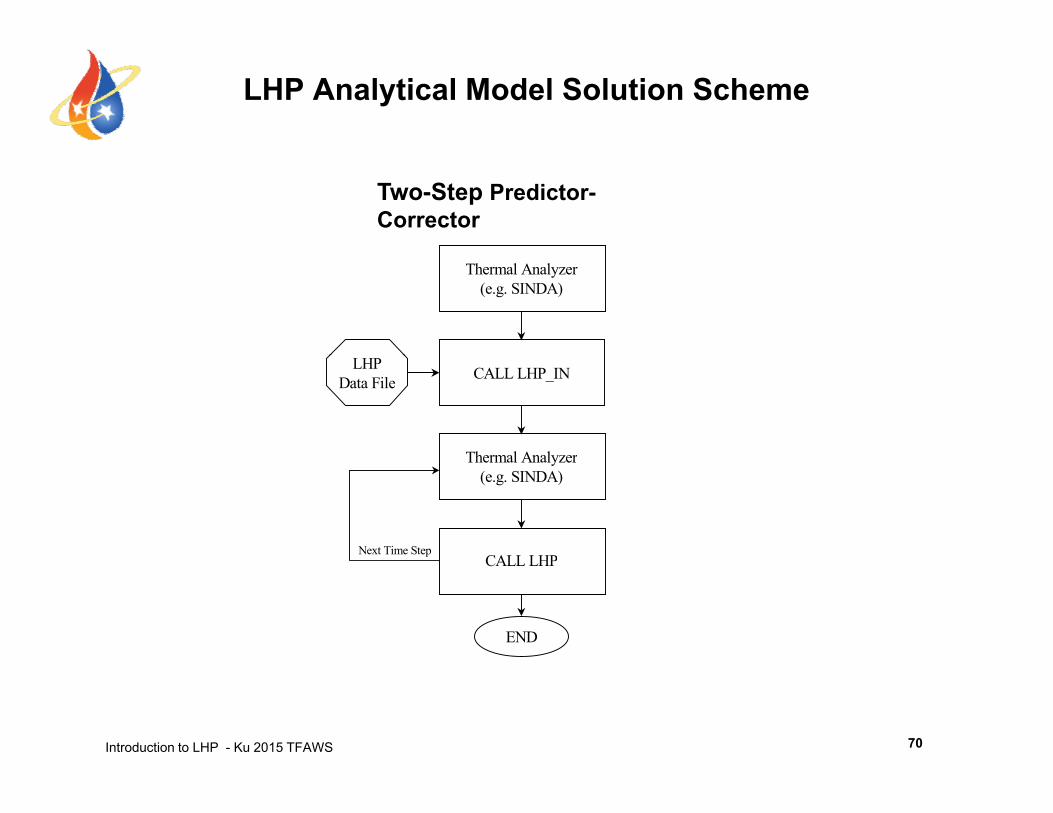
LHP Analytical Model Solution Scheme
Two-Step Predictor-Corrector
Thermal Analyzer(e.g. SINDA)
Thermal Analyzer
CALL LHP_INLHPData File
Thermal Analyzer(e.g. SINDA)
CALL LHPNext Time Step
CALL LHP
END
Introduction to LHP - Ku 2015 TFAWS 70
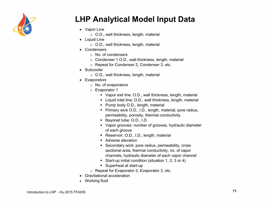
LHP Analytical Model Input Data Vapor Line
o O.D., wall thickness, length, material Li id Li Liquid Line
o O.D., wall thickness, length, material Condensers
o No. of condensers o Condenser 1 O.D., wall thickness, length, material o Repeat for Condenser 2 Condenser 3 etco Repeat for Condenser 2, Condenser 3, etc.
Subcooler o O.D., wall thickness, length, material
Evaporators o No. of evaporators o Evaporator 1p
Vapor exit line: O.D., wall thickness, length, material Liquid inlet line: O.D., wall thickness, length, material Pump body O.D., length, material Primary wick O.D., I.D., length, material, pore radius,
permeability, porosity, thermal conductivity Bayonet tube: O.D., I.D. Vapor grooves: number of grooves, hydraulic diameter
of each groove Reservoir: O.D., I.D., length, material Adverse elevation
S d i k di bilit Secondary wick: pore radius, permeability, cross sectional area, thermal conductivity, no. of vapor channels, hydraulic diameter of each vapor channel
Start-up initial condition (situation 1, 2, 3 or 4) Superheat at start-up
o Repeat for Evaporator 2 Evaporator 3 etc
Introduction to LHP - Ku 2015 TFAWS
o Repeat for Evaporator 2, Evaporator 3, etc. Gravitational acceleration Working fluid
71
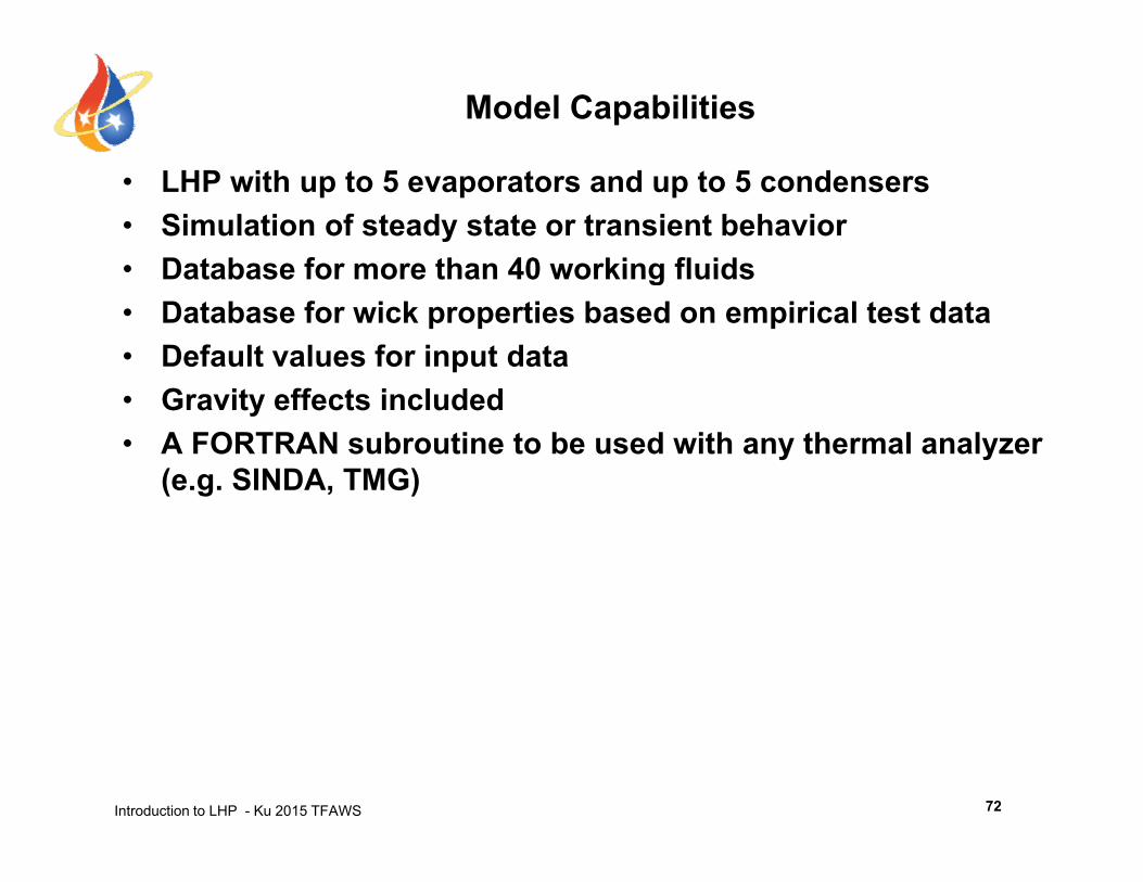
Model Capabilities
• LHP with up to 5 evaporators and up to 5 condensers• Simulation of steady state or transient behavior• Database for more than 40 working fluidsDatabase for more than 40 working fluids• Database for wick properties based on empirical test data• Default values for input data• Gravity effects included• A FORTRAN subroutine to be used with any thermal analyzer
(e.g. SINDA, TMG)
Introduction to LHP - Ku 2015 TFAWS 72
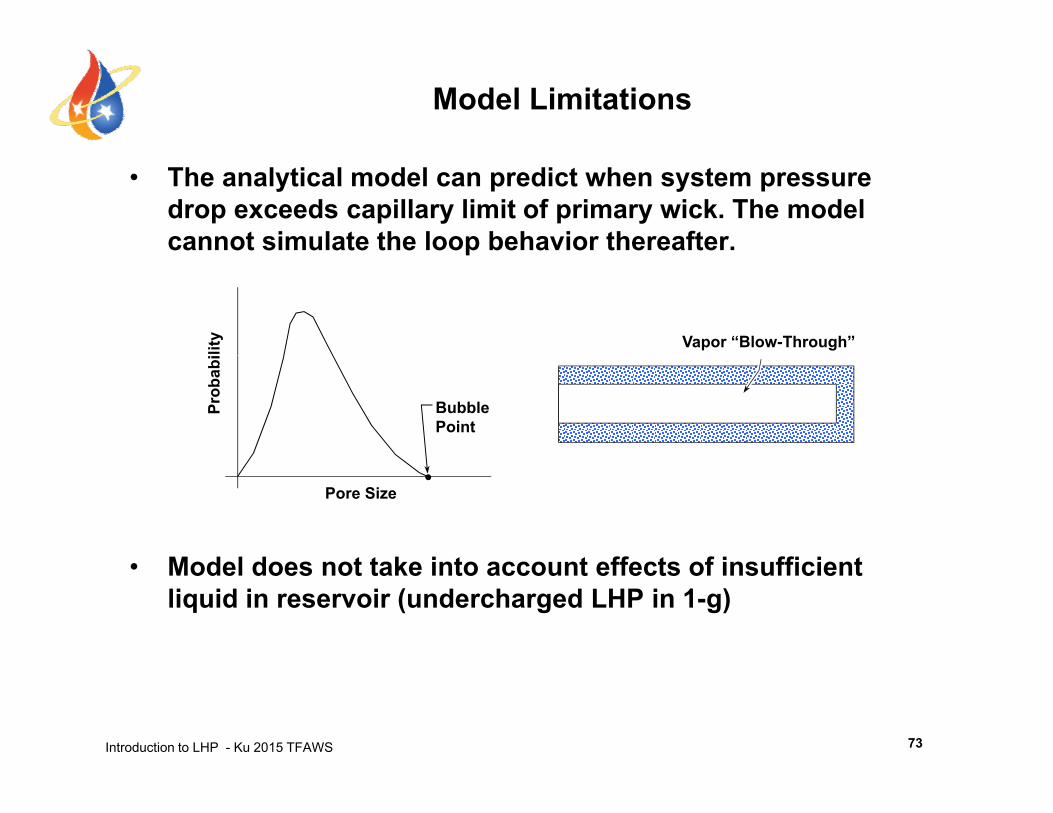
Model Limitations
• The analytical model can predict when system pressure drop exceeds capillary limit of primary wick. The model cannot simulate the loop behavior thereafter. p
lity Vapor “Blow-Through”
BubblePoint
Prob
abi
M d l d t t k i t t ff t f i ffi i t
Pore Size
• Model does not take into account effects of insufficient liquid in reservoir (undercharged LHP in 1-g)
Introduction to LHP - Ku 2015 TFAWS 73
Outline
• From Heat Pipe to Loop Heat Pipe and Capillary Pumped Loop
• LHP Operating PrinciplesLHP Operating Principles• LHP Components Sizing and Fluid Inventory• LHP Operating Temperature Control• LHP Start-up and Shutdown• LHP Analytical Modeling• Recent LHP Technology Developments• Recent LHP Technology Developments• Summary
Introduction to LHP - Ku 2015 TFAWS 2
Recent LHP Technology Developments
• Miniature LHP– 6.35 mm diameter evaporator
• A Single LHP with Multiple Evaporators and Multiple Condensers
C /• Hybrid CPL/LHP
• Cryogenic LHP– Nitrogen LHP: ~75K - 100K– Neon LHP: ~28K- 44K– Hydrogen LHP: ~20K - 30K– Helium LHP: ~2.7K - 4.4K
Introduction to LHP - Ku 2015 TFAWS 75
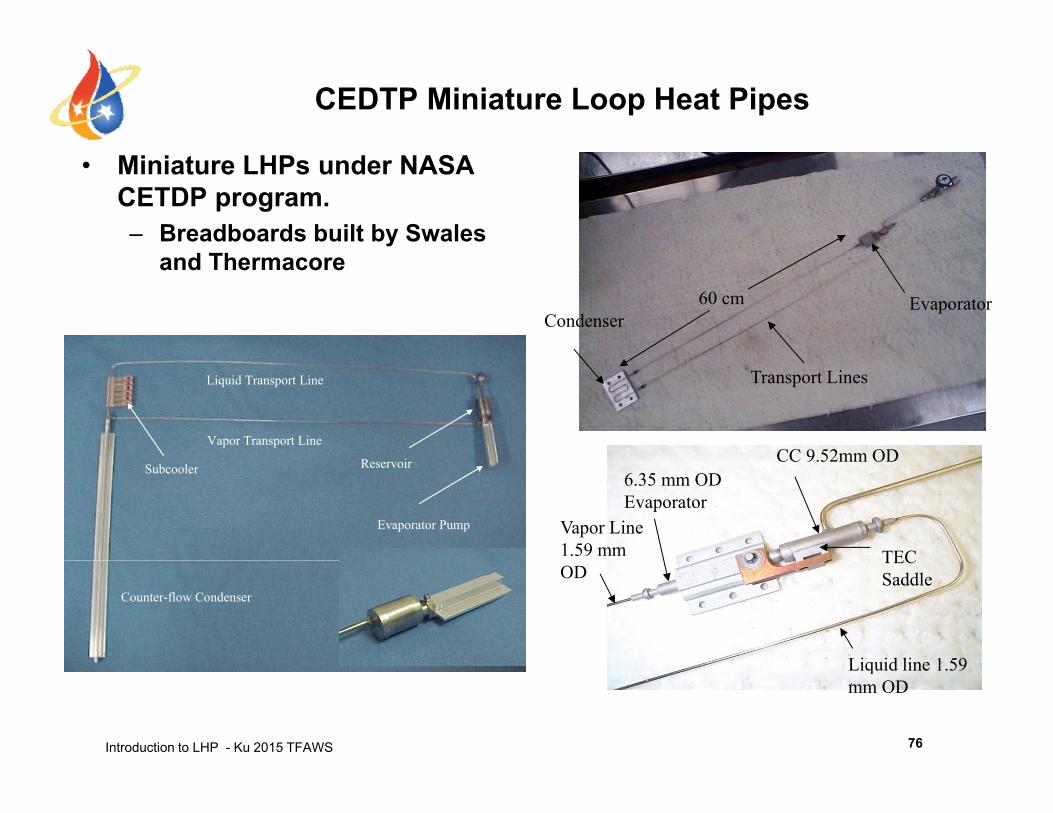
CEDTP Miniature Loop Heat Pipes
• Miniature LHPs under NASA CETDP program.– Breadboards built by Swales
d Thand Thermacore
CondenserEvaporator60 cm
Liquid Transport Line
Vapor Transport Line
Transport Lines
CC 9 52mm OD
Evaporator Pump
ReservoirSubcooler
Vapor Line 1.59 mm
6.35 mm OD Evaporator
CC 9.52mm OD
TEC
Counter-flow Condenser
Liquid line 1 59
ODTEC Saddle
Introduction to LHP - Ku 2015 TFAWS
Liquid line 1.59 mm OD
76
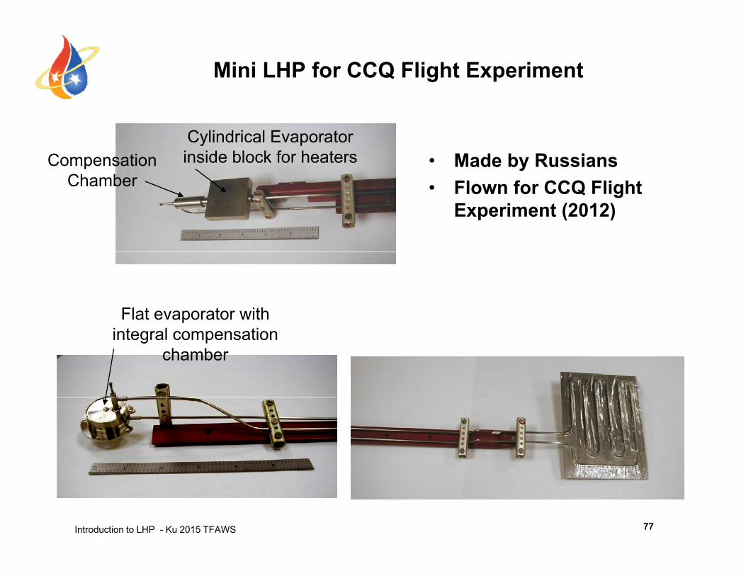
Mini LHP for CCQ Flight Experiment
• Made by RussiansCylindrical Evaporator inside block for heatersCompensation
Chamber • Flown for CCQ Flight Experiment (2012)
Chamber
Flat evaporator with integral compensation
chamber
Introduction to LHP - Ku 2015 TFAWS 77
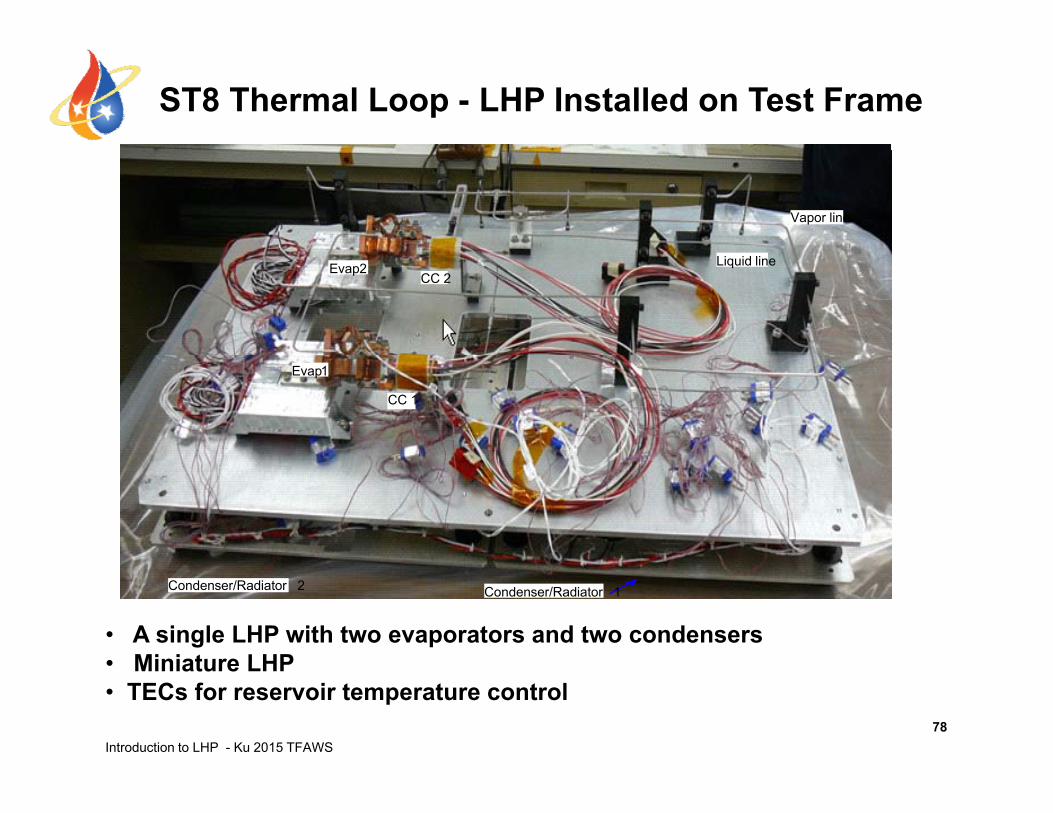
ST8 Thermal Loop - LHP Installed on Test Frame
Evap2
Li id li
Vapor lineVapor lineEvap2
Li id li
Vapor lineVapor line
CC 2Liquid line
Evap2CC 2
Liquid lineCC 2
Liquid lineEvap2
CC 2Liquid line
Evap1 CC 1
C d 2
Evap1
CC 1Evap1 CC 1
C d 2
Evap1
CC 1
Condenser 1Condenser 2
Condenser 1Condenser 2
Condenser/Radiator 2 Condenser/Radiator 1Condenser/Radiator 2 Condenser/Radiator 1
• A single LHP with two evaporators and two condensers• Miniature LHP
Introduction to LHP - Ku 2015 TFAWS78
• Miniature LHP• TECs for reservoir temperature control
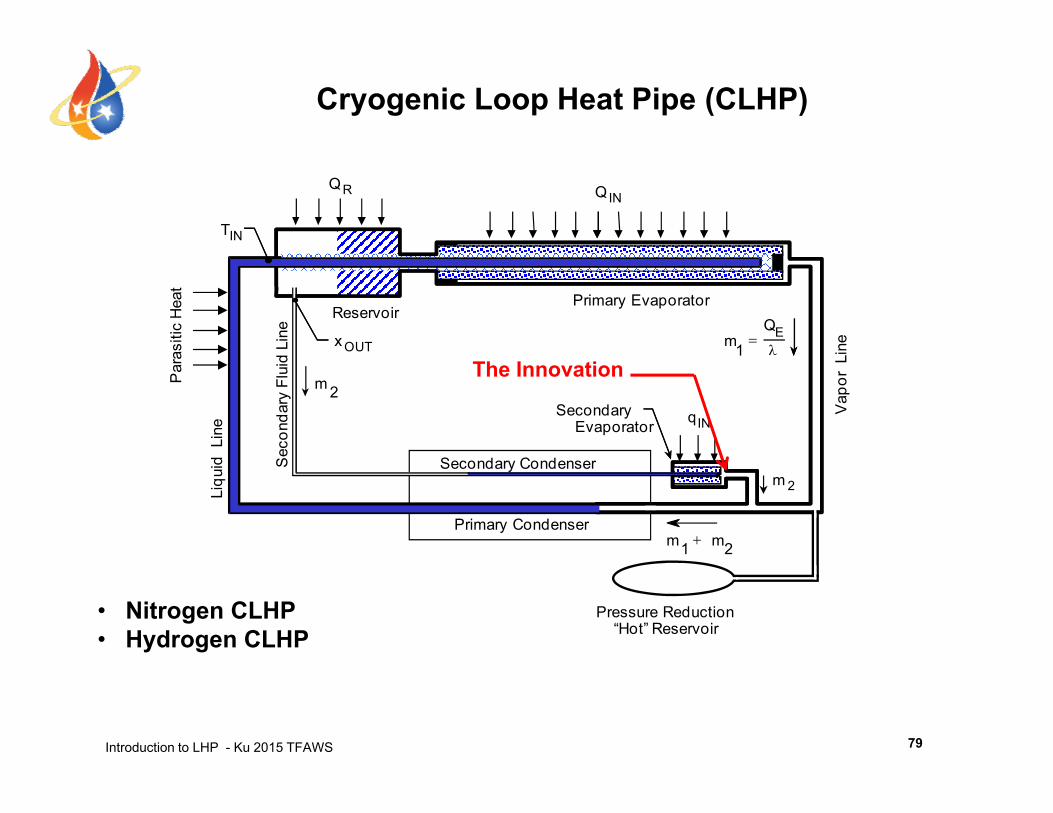
Cryogenic Loop Heat Pipe (CLHP)
INQRQ
INT
Primary EvaporatorReservoir
E
1Q
mOUTx
Line L
ine
asiti
c H
eat
SecondaryEvaporator
1
INq2m
S d C d
Vap
or L
d L
ine
econ
dary
Flu
id
Par
a
The Innovation
2m
21 mm Primary Condenser
Secondary Condenser
Liqu
id S
Pressure Reduction“Hot” Reservoir
• Nitrogen CLHP• Hydrogen CLHP
Introduction to LHP - Ku 2015 TFAWS 79
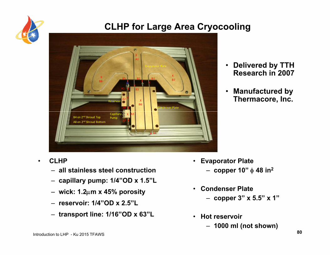
CLHP for Large Area Cryocooling
• Delivered by TTH Research in 2007
X
X
XB2B5 B7B1
A1
Evaporator Plate
• Manufactured by Thermacore, Inc.
XX
X
XX
B6
A2
B2B5 B7B1
B3
XB8
Reservoir
Condenser Plate
XA5
XA6
X
X
A3
A4
A8 on 2nd Shroud Bottom
Capillary Pump
XA7B4 on 2nd Shroud Top
• CLHP– all stainless steel construction
• Evaporator Plate– copper 10” 48 in2
– capillary pump: 1/4”OD x 1.5”L– wick: 1.2m x 45% porosity– reservoir: 1/4”OD x 2.5”L
• Condenser Plate– copper 3” x 5.5” x 1”
Introduction to LHP - Ku 2015 TFAWS
– transport line: 1/16”OD x 63”L • Hot reservoir– 1000 ml (not shown)
80
Other Advanced Topics Not Covered in This Course
• Temperature Oscillations in LHPs
• Temperature Hysteresis
• Effect of Secondary Wick on LHP Transient Operation
• Start-up and Re-start due to Reservoir Cold Shock
M lti l LHP S i Si l C t (S ift ABT• Multiple LHPs Serving a Single Components (Swift ABT , GOES-R ABI, and GOES-R GLM)
• Gravity Effects
• LHP with Multiple Parallel Evaporators
Introduction to LHP - Ku 2015 TFAWS
p p
81
Outline
• From Heat Pipe to Loop Heat Pipe and Capillary Pumped Loop
• LHP Operating PrinciplesLHP Operating Principles• LHP Components Sizing and Fluid Inventory• LHP Operating Temperature Control• LHP Start-up and Shutdown• LHP Analytical Modeling• Recent LHP Technology Developments• Recent LHP Technology Developments• Summary
Introduction to LHP - Ku 2015 TFAWS 2
LHP Summary (1 of 3)
K t hi h h t t t bilit f LHP• Key to high heat transport capability of LHP– Metal wicks with very fine porous wick– High thermal conductivity of the wick affects operating temperature
K t b t LHP ti• Key to robust LHP operation– Integral evaporator and CC design– Secondary wick connecting CC to evaporator: vapor tolerant
K t d t di LHP ti• Key to understanding LHP operation– CC saturation temperature governs the loop operating temperature– CC is plumbed in line with flow circulation
CC t t it lf ff t d b ti diti– CC temperature itself affected by operating conditions – Thermodynamic constraints: P is linked to T – CC volume and liquid inventory
K d i i CC i• Key to determining CC saturation temperature– Net heat gain must be balanced by subcooling of returning liquid– Ambient temperature affects liquid subcooling
Introduction to LHP - Ku 2015 TFAWS 83
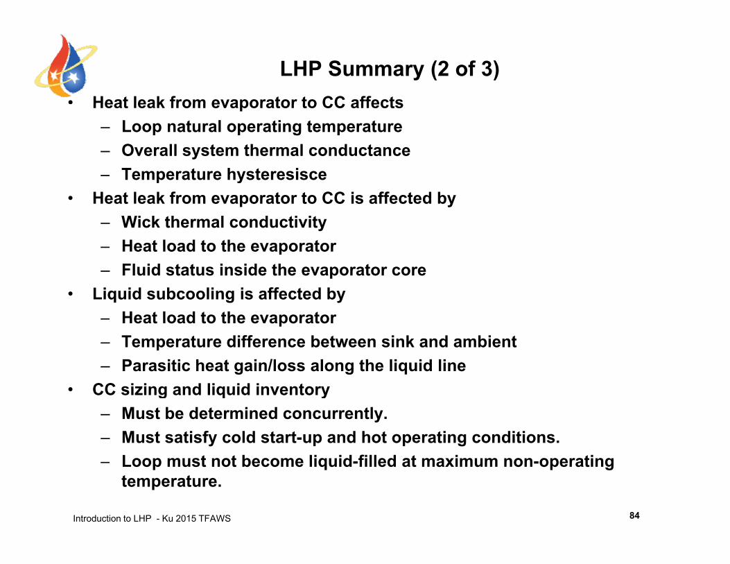
LHP Summary (2 of 3)• Heat leak from evaporator to CC affectsHeat leak from evaporator to CC affects
– Loop natural operating temperature– Overall system thermal conductance– Temperature hysteresisce– Temperature hysteresisce
• Heat leak from evaporator to CC is affected by– Wick thermal conductivity
Heat load to the evaporator– Heat load to the evaporator– Fluid status inside the evaporator core
• Liquid subcooling is affected byHeat load to the evaporator– Heat load to the evaporator
– Temperature difference between sink and ambient– Parasitic heat gain/loss along the liquid line
• CC sizing and liquid inventory• CC sizing and liquid inventory– Must be determined concurrently.– Must satisfy cold start-up and hot operating conditions.
Loop must not become liquid filled at maximum non operating
Introduction to LHP - Ku 2015 TFAWS
– Loop must not become liquid-filled at maximum non-operating temperature.
84
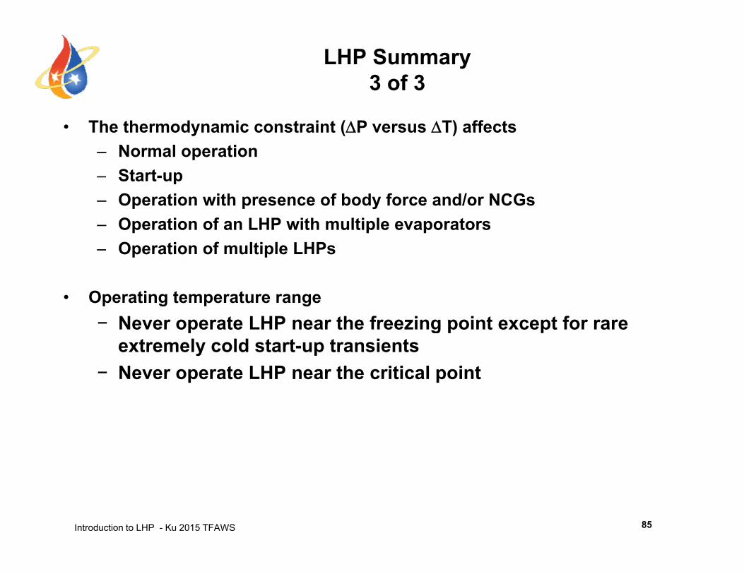
LHP Summary3 of 3
• The thermodynamic constraint (P versus T) affects – Normal operation – Start-upStart up– Operation with presence of body force and/or NCGs– Operation of an LHP with multiple evaporators– Operation of multiple LHPsOperation of multiple LHPs
• Operating temperature range− Never operate LHP near the freezing point except for rare− Never operate LHP near the freezing point except for rare
extremely cold start-up transients− Never operate LHP near the critical point
Introduction to LHP - Ku 2015 TFAWS 85

Questions?Questions?
Introduction to LHP - Ku 2015 TFAWS 86
![NANOFLUIDS IN HEAT PIPES - coolingzone · NANOFLUIDS IN HEAT PIPES Figure 1. A Heat Pipe and its Thermal Resistance Network [1] Heat pipes are simple heat transfer devices that are](https://static.documents.pub/doc/80x56/5e1709ba99d6092e366c9a76/nanofluids-in-heat-pipes-nanofluids-in-heat-pipes-figure-1-a-heat-pipe-and-its.jpg)


