30
Introduction to LTspice 6.101 Spring 2014 Lecture 4

Introduction to LTspice
6.101 Spring 2014 Lecture 4
SPICE
• Simulation Program with Integrated Circuit Emphasis
• Developed in 1973 by Laurence Nagel at UC Berkeley’s Electronics Research Laboratory
• Dependent on user defined device models
6.101 Spring 2014 Lecture 4 2

Netlists
6.101 Spring 2014 Lecture 4
Components
Commands
3

LTspice
• Developed in 1998 by Mike Engelhardt at Linear Technology Corporation
• GUI, simulator, and schematic -> netlist for SPICE • FREE and comes with tons of models
6.101 Spring 2014 Lecture 4
You do this Ltspice makes this
4

Getting Started
6.101 Spring 2014 Lecture 4
THAT’S IT!
These buttons are where you will live
5
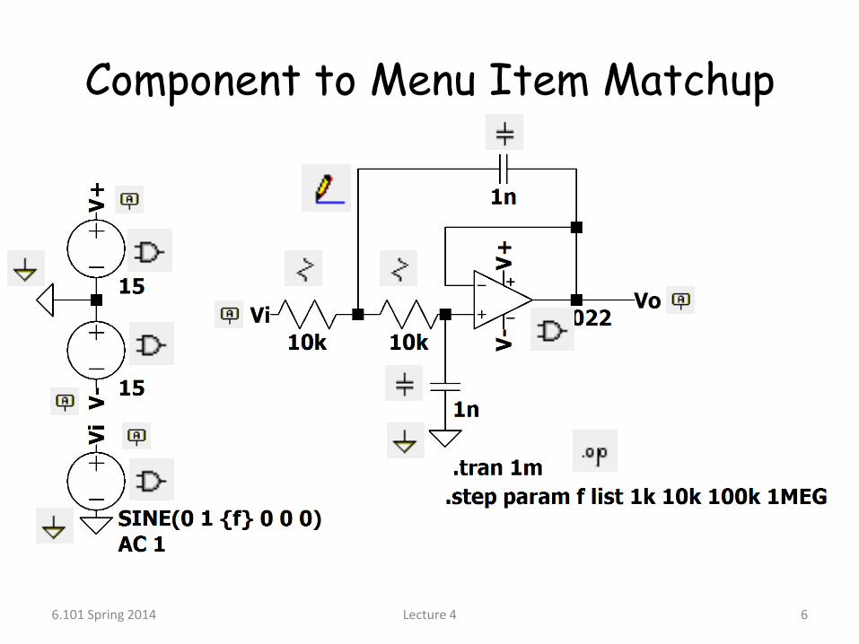
Component to Menu Item Matchup
6.101 Spring 2014 Lecture 4 6

Net Labels
6.101 Spring 2014 Lecture 4
By labeling nets you can avoid a giant mess of wires. Always use these for at least your power supplies. When you start making large circuits, your power supplies will provide energy all over your schematic.
7

Adding Other Components
6.101 Spring 2014 Lecture 4
Devices besides basic resistors, capacitors, and inductors are found from this button
8

Op-Amps
6.101 Spring 2014 Lecture 4
There are no “ideal” op-amps in LTspice. BUT, you can select from any of Linear Tech’s… which (in some cases) are close.
(LT1022 is my “go-to”)
9

Editing Components
6.101 Spring 2014 Lecture 4
Just right click the component
10

Editing Components
6.101 Spring 2014 Lecture 4
This is the basic voltage source menu. Use this for DC sources such as power supplies or bias voltages.
But what about this?
11

Editing Components
6.101 Spring 2014 Lecture 4
Voltage sources can produce many test signals. PWL can be used to construct any signal.
12

Selecting Device Model
6.101 Spring 2014 Lecture 4
There are no “ideal” BJT’s, MOSFET’s, Diode’s, etc. You must select a model (provided by LTspice).
13

Simulation: Transient Transient simulation gives Voltage and/or Current
vs.time.
6.101 Spring 2014 Lecture 4
These are transient parameters for a voltage source
14

Simulation: Transient
6.101 Spring 2014 Lecture 4
This is all you really need
15

Random Tangent: Parameters
6.101 Spring 2014 Lecture 4
This is a parameter
You MUST define all of your parameters. The “list” command allows you to choose multiple values (simulation simulates each value separately).
16

What Should My Circuit Do?
• The very first step to any simulation is to know how your circuit should behave. Simulation is a verification tool NOT A CIRCUIT SOLVER.
• So how should this circuit behave?
6.101 Spring 2014 Lecture 4 17

Here’s Where You Write the Solution
6.101 Spring 2014 Lecture 4
vx vo
i1
i2
i3
A DOUBLE POLE!!
18
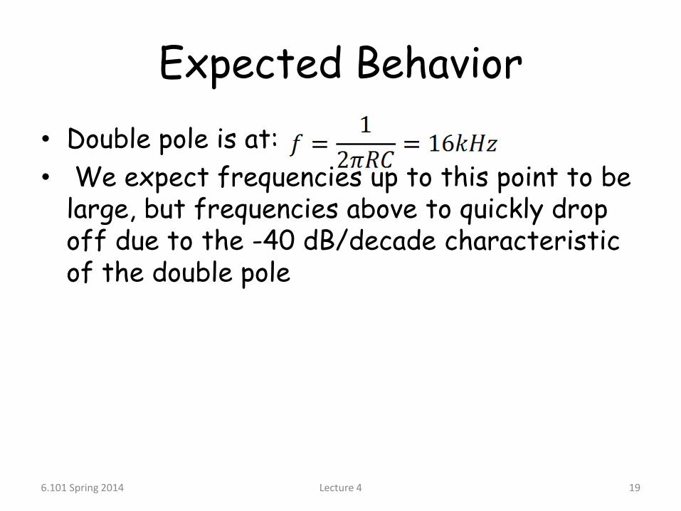
Expected Behavior
• Double pole is at:
• We expect frequencies up to this point to be large, but frequencies above to quickly drop off due to the -40 dB/decade characteristic of the double pole
6.101 Spring 2014 Lecture 4 19
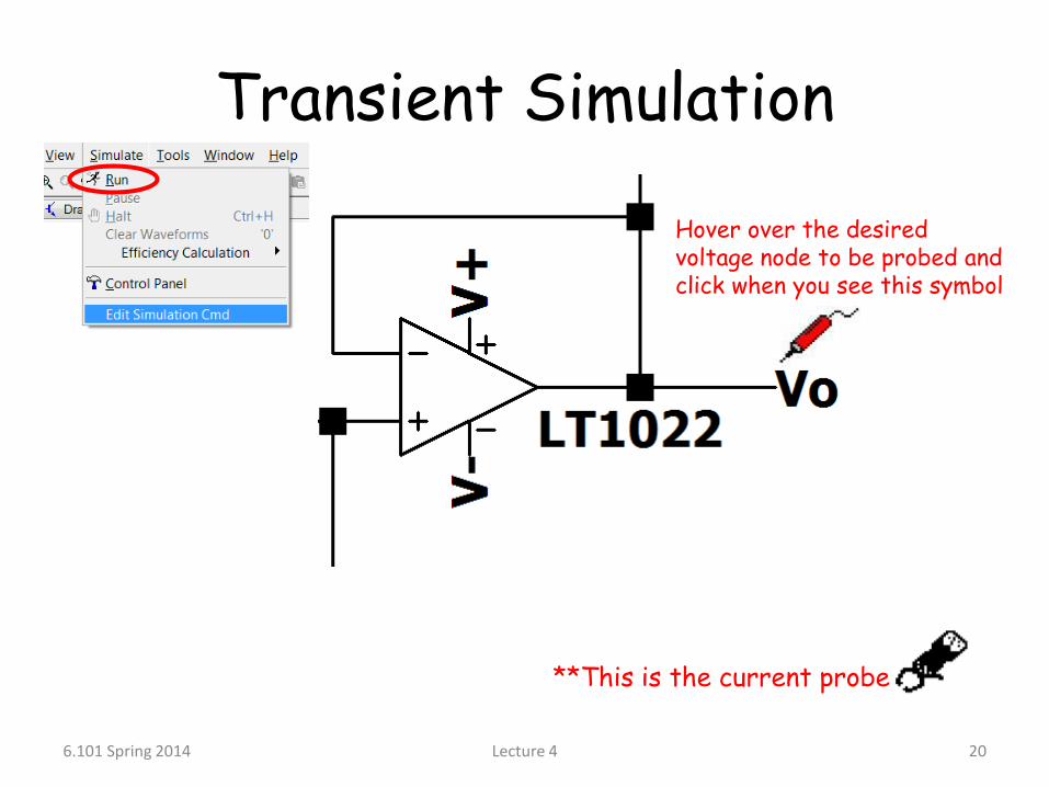
Transient Simulation
6.101 Spring 2014 Lecture 4
Hover over the desired voltage node to be probed and click when you see this symbol
**This is the current probe
20

Transient Simulation
6.101 Spring 2014 Lecture 4
1 kHz
10 kHz
100 kHz
1 MHz
21

AC Simulation
6.101 Spring 2014 Lecture 4
This is the AC parameter. Just set the amplitude to 1
AC simulation gives Voltage and/or Current vs.frequency.
22

AC Simulation
6.101 Spring 2014 Lecture 4 23

Extra Fun: Math in LTspice
6.101 Spring 2014 Lecture 4
Remember:
24

Transient Simulation
6.101 Spring 2014 Lecture 4
It’s the same as before!
25

Even More Fun
6.101 Spring 2014 Lecture 4 26

AC Simulation
6.101 Spring 2014 Lecture 4 27

Making Things Pretty
6.101 Spring 2014 Lecture 4 28
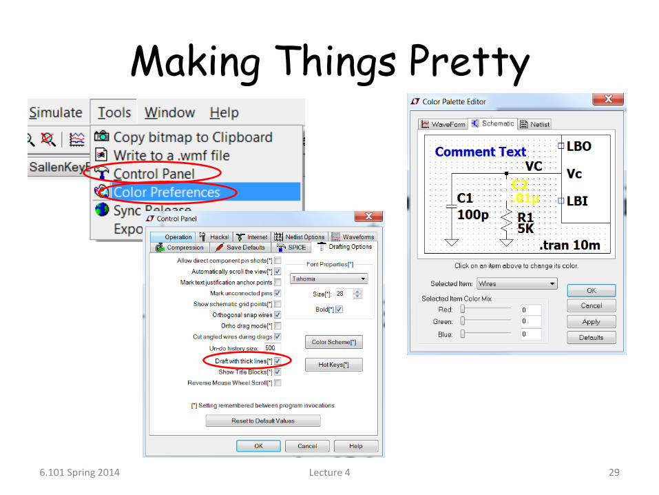
Making Things Pretty
6.101 Spring 2014 Lecture 4 29

Questions??
6.101 Spring 2014 Lecture 4 30


