21
Microcomputer Architecture and Interfacing Colorado School of Mines Professor William Hoff Output Compare 1

Microcomputer Architecture and Interfacing Colorado School of Mines Professor William Hoff
Output Compare
1

Microcomputer Architecture and Interfacing Colorado School of Mines Professor William Hoff
• Input capture
• Output compare
Timer System
2
Free running counter
Capture register
E-clock
Capture signal
Free running counter
Compare register
E-clock
Match signal Comparator
When an input signal arrives, the value in the counter is automatically latched into a capture register
When the value in the counter matches a value in a compare register, an output signal is automatically generated
Microcomputer Architecture and Interfacing Colorado School of Mines Professor William Hoff
Output Compare
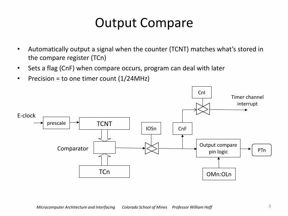
• Automatically output a signal when the counter (TCNT) matches what’s stored in the compare register (TCn)
• Sets a flag (CnF) when compare occurs, program can deal with later
• Precision = to one timer count (1/24MHz)
E-clock
TCNT
TCn
Comparator
prescale IOSn CnF
CnI
Output compare pin logic
OMn:OLn
PTn
Timer channel interrupt
3

Microcomputer Architecture and Interfacing Colorado School of Mines Professor William Hoff
Using output compare
• One of the applications of the output compare function is to trigger an action at a specific time in the future
• To use output compare in this way, the user
– makes a copy of the current contents of the TCNT register
– adds to this copy a value equal to the desired delay
– stores the sum into an output-compare register (TCn, where n=0..7)
• When the compare (match) happens, these events occur:
– the output pin changes state (ie., goes high, low, or toggles, depending on what you select)
– the compare flag (CnF bit) is set
– an interrupt occurs, if you enable it (i.e., set CnI bit to 1)
4

Microcomputer Architecture and Interfacing Colorado School of Mines Professor William Hoff
Input Capture & Output Compare
• There are 8 channels, all driven by the same free running counter
• Each channel can be configured to be input capture or output compare
5
Prescaler
16-bit counter
Input Capture
Output compare
Channel 0
Input Capture
Output compare
Channel 1
Input Capture
Output compare
Channel 2
Input Capture
Output compare
Channel 3
Input Capture
Output compare
Channel 4
Input Capture
Output compare
Channel 5
Input Capture
Output compare
Channel 6
Input Capture
Output compare
Channel 7
Registers
16-bit Pulse
accumulator A
IOC0
IOC1
IOC2
IOC3
IOC4
IOC5
IOC6
IOC7
Bus clock
Timer overflow
interrupt
TC0 interrupt
TC1 interrupt
TC2 interrupt
TC3 interrupt
TC4 interrupt
TC5 interrupt
TC6 interrupt
TC7 interrupt
PA overflow
interrupt
PA input
interrupt
Figure 8.1 HCS12 Standard Timer (TIM) block diagram

Microcomputer Architecture and Interfacing Colorado School of Mines Professor William Hoff
Channels
• Each channel can be configured as either input capture or output compare, using the TIOS register:
• The following instruction will enable output compare on channels 7...4 and input capture on channels 3…0:
movb #$F0,TIOS
6
7 6 5 4 3 2 1 0
IOS7 IOS6 IOS5 IOS4 IOS3 IOS2 IOS1 IOS0value
after reset 0 0 0 0 0 0 0 0
Figure 8.5 Timer input capture/output compare select register (TIOS)
IOS[7:0] -- Input capture or output compare channel configuration bits
0 = The corresponding channel acts as an input capture
1 = The corresponding channel acts as an output compare
Microcomputer Architecture and Interfacing Colorado School of Mines Professor William Hoff
Output Compare Registers
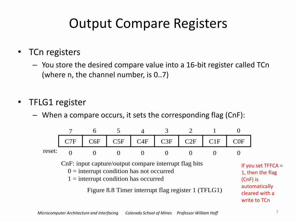
• TCn registers – You store the desired compare value into a 16-bit register called TCn
(where n, the channel number, is 0..7)
• TFLG1 register – When a compare occurs, it sets the corresponding flag (CnF):
7
7 6 5 4 3 2 1 0
C7F C6F C5F C4F C3F C2F C1F C0F
reset: 0 0 0 0 0 0 0 0
Figure 8.8 Timer interrupt flag register 1 (TFLG1)
CnF: input capture/output compare interrupt flag bits
0 = interrupt condition has not occurred
1 = interrupt condition has occurred
If you set TFFCA = 1, then the flag (CnF) is automatically cleared with a write to TCn
Microcomputer Architecture and Interfacing Colorado School of Mines Professor William Hoff
Output Compare Registers
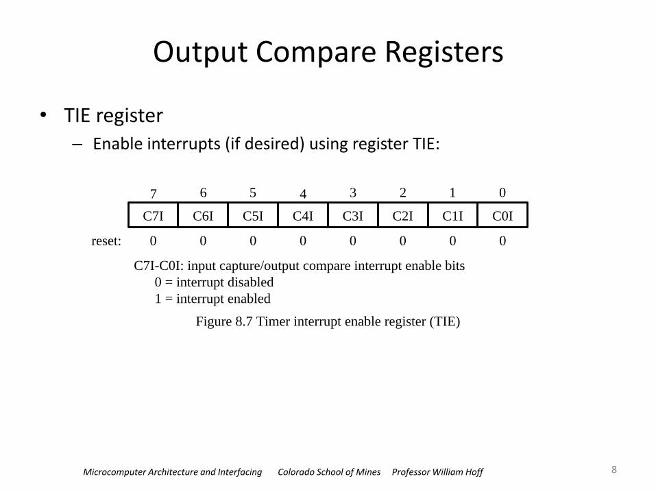
• TIE register – Enable interrupts (if desired) using register TIE:
8
7 6 5 4 3 2 1 0
C7I C6I C5I C4I C3I C2I C1I C0I
reset: 0 0 0 0 0 0 0 0
Figure 8.7 Timer interrupt enable register (TIE)
C7I-C0I: input capture/output compare interrupt enable bits
0 = interrupt disabled
1 = interrupt enabled

Microcomputer Architecture and Interfacing Colorado School of Mines Professor William Hoff
Output compare
• You can specify what action to be taken when a match occurs
• Registers TCTL1 and TCTL2:
9
Rising edge Falling edge
or
Figure 8.4 Events represented by signal edges
7 6 5 4 3 2 1 0
OM7 OL7 OM6 OL6 OM5 OL5 OM4 OL4value
after reset 0 0 0 0 0 0 0 0
read: anytime
write: anytime
Figure 8.18 Timer control register 1 and 2 (TCTL1 & TCTL2)
7 6 5 4 3 2 1 0
OM3 OL3 OM2 OL2 OM1 OL1 OM0 OL0
0 0 0 0 0 0 0 0
(a) TCTL1 register
(b) TCTL2 register
value
after reset
OMn OLn : output level
0
0
1
1
0
1
0
1
no action (timer disconnected from output pin)
toggle OCn pin
clear OCn pin to 0
set OCn pin to high
Microcomputer Architecture and Interfacing Colorado School of Mines Professor William Hoff
Summary of registers associated with output compare
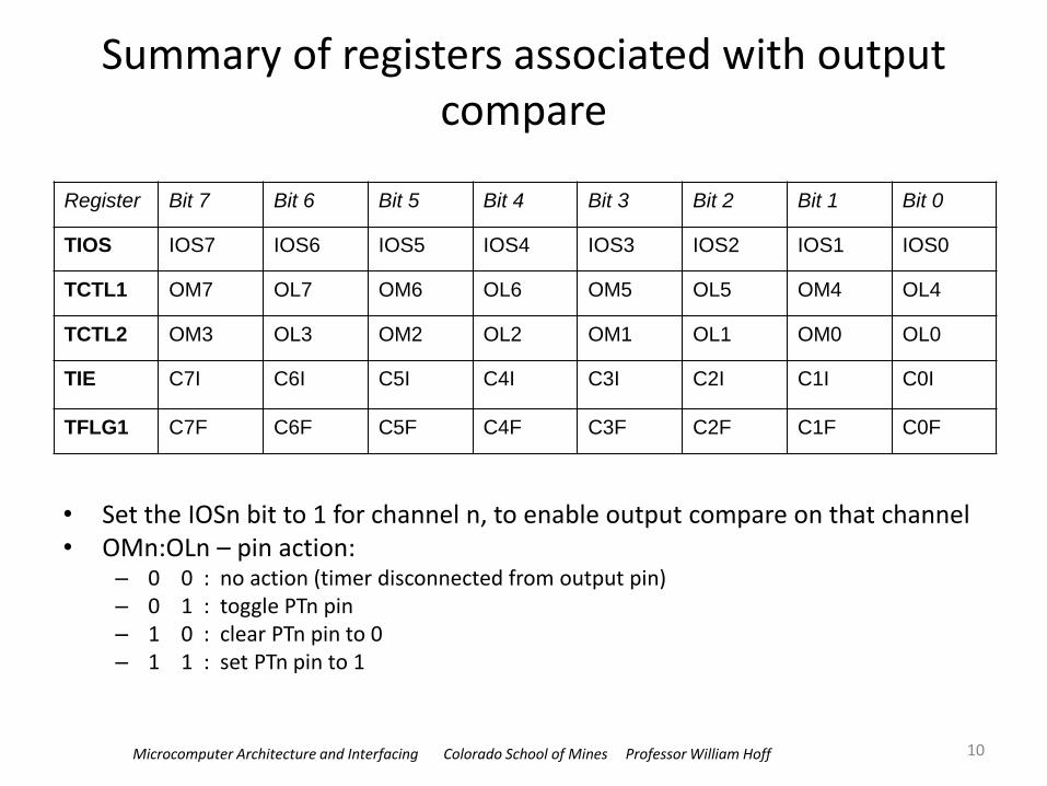
• Set the IOSn bit to 1 for channel n, to enable output compare on that channel • OMn:OLn – pin action:
– 0 0 : no action (timer disconnected from output pin) – 0 1 : toggle PTn pin – 1 0 : clear PTn pin to 0 – 1 1 : set PTn pin to 1
10
Register Bit 7 Bit 6 Bit 5 Bit 4 Bit 3 Bit 2 Bit 1 Bit 0
TIOS IOS7 IOS6 IOS5 IOS4 IOS3 IOS2 IOS1 IOS0
TCTL1 OM7 OL7 OM6 OL6 OM5 OL5 OM4 OL4
TCTL2 OM3 OL3 OM2 OL2 OM1 OL1 OM0 OL0
TIE C7I C6I C5I C4I C3I C2I C1I C0I
TFLG1 C7F C6F C5F C4F C3F C2F C1F C0F

Microcomputer Architecture and Interfacing Colorado School of Mines Professor William Hoff
Example
• Use output compare to generate an active high 1 KHz digital waveform with 30 percent duty cycle from the PT5 pin (example 8.4)
• We’ll need to time an interval of up to 700 us
• Make sure that the 16-bit counter TCNT can time an interval that long – We may need to prescale the clock input to TCNT
11
300 s
700 s
Figure 8.19 1 KHz 30 percent duty cycle waveform

Microcomputer Architecture and Interfacing Colorado School of Mines Professor William Hoff
A helpful table
• This shows the clock period (i.e., the time of 1 tick) and how long the counter takes to overflow, for different values of the prescale factor
12
/* Bottom three bits of TSCR2
(PR2,PR1,PR0) determine TCNT period
divide at 24MHz
000 1 42ns TOF 2.73ms
001 2 84ns TOF 5.46ms
010 4 167ns TOF 10.9ms
011 8 333ns TOF 21.8ms
100 16 667ns TOF 43.7ms
101 32 1.33us TOF 87.4ms
110 64 2.67us TOF 174.8ms
111 128 5.33us TOF 349.5ms */
• Even at the fastest clock rate, the timer won’t overflow until 2.73 ms
• So any of these rates are ok

Microcomputer Architecture and Interfacing Colorado School of Mines Professor William Hoff
Example (continued)
• We will use the fastest clock rate (prescale factor = 1)
– At that rate, each tick is 1/24 MHz = 42 ns
• Then the number of ticks is
– The high portion of the period is 300 us
HiCnt = (300 us)/(42 ns) = 7200 ticks
– The low portion of the period is 700 us
LoCnt = (700 us)/(42 ns) = 16800 ticks
13

Microcomputer Architecture and Interfacing Colorado School of Mines Professor William Hoff
Approach for example (continued)
• Output pin – We’ll use channel 5
– Force PT5 pin high (not necessary if you don’t care when the pulse train starts)
– Then every time a compare action occurs, change PT5
14
300 s
700 s
Figure 8.19 1 KHz 30 percent duty cycle waveform
• Interrupt action – The interrupt service routine (ISR) simply adds the appropriate
delay (HiCnt or LoCnt) to the compare register
– It needs to know if the pin is currently in the high state or low state (to determine this, we’ll look at register TCTL1 to see what the last action was configured to be)

Microcomputer Architecture and Interfacing Colorado School of Mines Professor William Hoff
Algorithm steps for example
• Set up timer – TSCR1 register
• Enable timer by setting TEN bit = 1
• Enable fast flag clear by setting TFFCA bit = 1
– TSCR2 register: Set timer prescale factor = 1
• Set up channel 5 for output compare – TIOS register: Set channel 5 to be output by setting IO5 bit = 1
– TCTL1 register: Set OM5:OL5 = 1:1 to make PT5 high upon compare
– TIE register: Enable interrupts on channel 5
• Enable global interrupts
• Go into infinite loop
15

Microcomputer Architecture and Interfacing Colorado School of Mines Professor William Hoff 16
#include <hidef.h>
#include "derivative.h“
#define HiCnt 7200 // high duration in timer counts
#define LoCnt 16800 // low duration in timer counts
void main(void)
{
/* Set up timer */
TSCR1 = 0x90; // enable timer counter, enable fast flag clear
TSCR2 = 0x00; // disable TCNT overflow interrupt, set prescaler=1
/* Set up output compare */
TIOS |= 0x20; // enable OC5 function
TCTL1 = 0x0c; // set first OC5 action to be go high
TIE = 0x20; // enable OC5 interrupt locally
/* (Optional) Make first compare action happen very soon. */
TC5 = TCNT + 10; // first action will be 10 ticks from now
EnableInterrupts; // enable global interrupts
for(;;) {
_FEED_COP(); /* feeds the dog */
} /* loop forever */
}
Main program

Microcomputer Architecture and Interfacing Colorado School of Mines Professor William Hoff
Interrupt Service Routine
17
void interrupt VectorNumber_Vtimch5 oc5ISR (void)
{
// Look at bits OM5:OL5 to see what OC5 was configured to do.
// OM5:OL5 bits are in TCTL1 at ----xx--.
if ( (TCTL1 & 0x0c) == 0x0c) {
// Bits OM5:OL5 are 1:1, so pin just went high.
TC5 += HiCnt; // add time for high duration
TCTL1 = 0x08; // set next action to go low
} else {
// Bits OM5:OL5 are 1:0, meaning pin just went low.
TC5 += LoCnt; // add time for low duration
TCTL1 = 0x0c; // set next action to go high
}
}
• This is how you define an ISR in CodeWarrior • The vector numbers are defined in the
include file mc9s12c32.h
TCNT is the current time. Why do we add HiCnt or LoCnt to TC5, instead of TCNT?

Microcomputer Architecture and Interfacing Colorado School of Mines Professor William Hoff
Example
• Use output compare to generate a square wave with a 15 ms period, with 2/3 duty cycle, on pin PT4
• We’ll need to time an interval of up to (2/3)*15 = 10 ms
• Looking at our handy table, we will need to prescale timer by a factor of 8
• At that rate, each tick is 8*(1/24 MHz) = 333 ns
• Then the number of ticks is – The high portion of the period is 10 ms
HiCnt = (10 ms)/(333 ns) = 30000 ticks
– The low portion of the period is 5 ms
LoCnt = (5 ms)/(333 ns) = 15000 ticks
18
time
PT4
5 ms
10 ms
15 ms
Microcomputer Architecture and Interfacing Colorado School of Mines Professor William Hoff 19
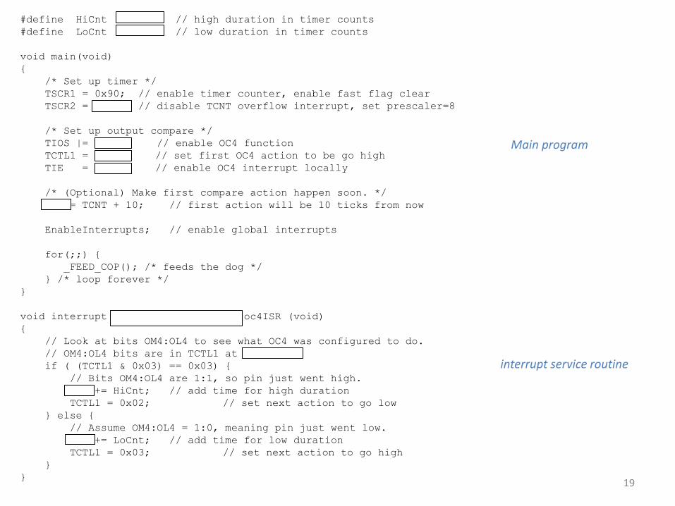
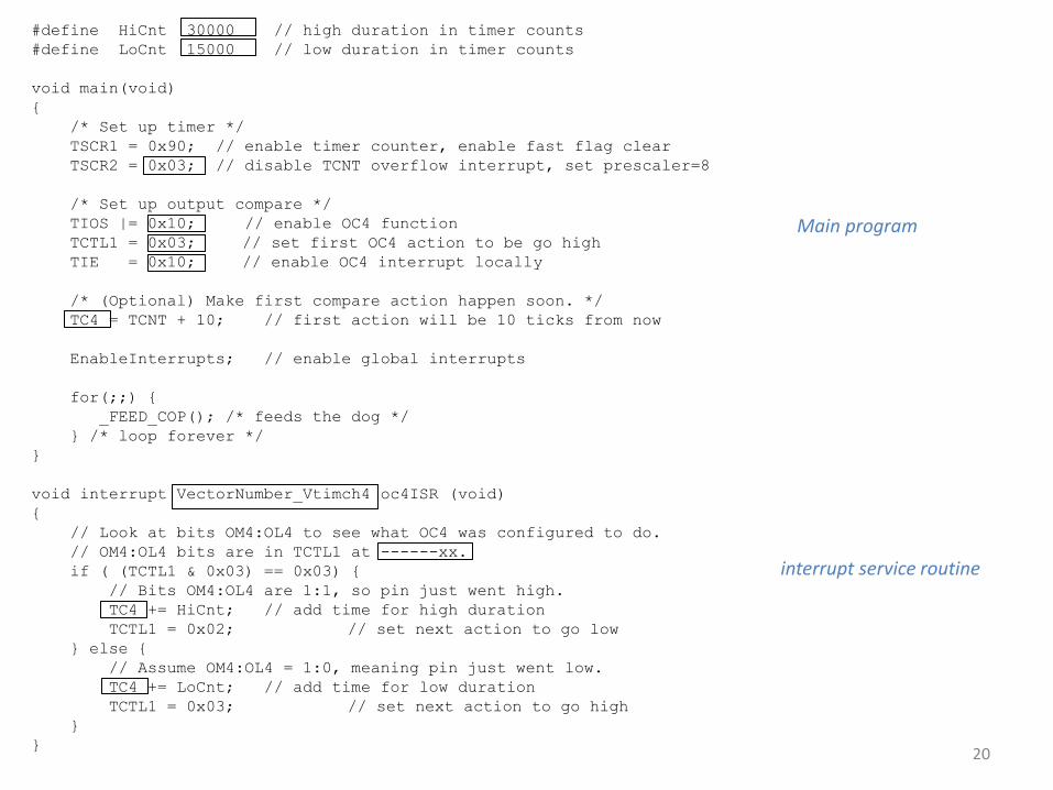
#define HiCnt 30000 // high duration in timer counts
#define LoCnt 15000 // low duration in timer counts
void main(void)
{
/* Set up timer */
TSCR1 = 0x90; // enable timer counter, enable fast flag clear
TSCR2 = 0x03; // disable TCNT overflow interrupt, set prescaler=8
/* Set up output compare */
TIOS |= 0x10; // enable OC4 function
TCTL1 = 0x03; // set first OC4 action to be go high
TIE = 0x10; // enable OC4 interrupt locally
/* (Optional) Make first compare action happen soon. */
TC4 = TCNT + 10; // first action will be 10 ticks from now
EnableInterrupts; // enable global interrupts
for(;;) {
_FEED_COP(); /* feeds the dog */
} /* loop forever */
}
void interrupt VectorNumber_Vtimch4 oc4ISR (void)
{
// Look at bits OM4:OL4 to see what OC4 was configured to do.
// OM4:OL4 bits are in TCTL1 at ------xx.
if ( (TCTL1 & 0x03) == 0x03) {
// Bits OM4:OL4 are 1:1, so pin just went high.
TC4 += HiCnt; // add time for high duration
TCTL1 = 0x02; // set next action to go low
} else {
// Assume OM4:OL4 = 1:0, meaning pin just went low.
TC4 += LoCnt; // add time for low duration
TCTL1 = 0x03; // set next action to go high
}
}
Main program
interrupt service routine
Microcomputer Architecture and Interfacing Colorado School of Mines Professor William Hoff 20
#define HiCnt 30000 // high duration in timer counts
#define LoCnt 15000 // low duration in timer counts
void main(void)
{
/* Set up timer */
TSCR1 = 0x90; // enable timer counter, enable fast flag clear
TSCR2 = 0x03; // disable TCNT overflow interrupt, set prescaler=8
/* Set up output compare */
TIOS |= 0x10; // enable OC4 function
TCTL1 = 0x03; // set first OC4 action to be go high
TIE = 0x10; // enable OC4 interrupt locally
/* (Optional) Make first compare action happen soon. */
TC4 = TCNT + 10; // first action will be 10 ticks from now
EnableInterrupts; // enable global interrupts
for(;;) {
_FEED_COP(); /* feeds the dog */
} /* loop forever */
}
void interrupt VectorNumber_Vtimch4 oc4ISR (void)
{
// Look at bits OM4:OL4 to see what OC4 was configured to do.
// OM4:OL4 bits are in TCTL1 at ------xx.
if ( (TCTL1 & 0x03) == 0x03) {
// Bits OM4:OL4 are 1:1, so pin just went high.
TC4 += HiCnt; // add time for high duration
TCTL1 = 0x02; // set next action to go low
} else {
// Assume OM4:OL4 = 1:0, meaning pin just went low.
TC4 += LoCnt; // add time for low duration
TCTL1 = 0x03; // set next action to go high
}
}
Main program
interrupt service routine
Microcomputer Architecture and Interfacing Colorado School of Mines Professor William Hoff
Summary / Questions
• “Output compare” is part of the timer system (“input capture” is the other part). It is used to generate output signals at precise times.
• Why is it called “compare” (what is being compared)?
• Why would you use output compare versus the PWM system?
21


