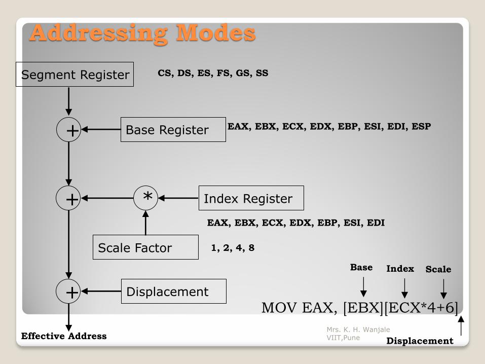
Unit I : Introduction to Microprocessor Architecture of 8086 and 80386DX, Register set, Flags, Physical address space of 8086, Data types, Addressing Modes, 80386DX Instruction Set. Mrs. K. H. Wanjale VIIT,Pune
Transcript
Unit I : Introduction to
Microprocessor
Architecture of 8086 and 80386DX, Register set, Flags, Physical address space
of 8086, Data types, Addressing Modes, 80386DX Instruction Set.
Mrs. K. H. Wanjale VIIT,Pune
Basic 8086 Architecture
Mrs. K. H. Wanjale VIIT,Pune
Term “16-bit” means that its arithmetic logic unit, internal registers, and most of its instructions are designed to work 16-bit binary words.
It has 16-bit data bus and 20-bit address bus.
Words will be stored in two consecutive memory locations.
If the first byte of a word is at an even address, the 8086 can read the entire word in one operation.
If the first byte of the word is at an odd address, the 8086 will read the first byte in one operation, and the second byte in another operation.
Mrs. K. H. Wanjale VIIT,Pune
The 8086 CPU is divided into two independent
functional units:
Bus Interface Unit (BIU)
Execution Unit (EU)
The Bus Interface Unit
The BIU handles all data and addresses on the buses
for the execution unit such as it sends out addresses,
fetches instructions from memory, reads data from
ports and memory as well as writes data to ports and
memory.
Mrs. K. H. Wanjale VIIT,Pune
The function of BIU is to:
◦ Fetch the instruction or data from memory.
◦ Write the data to memory.
◦ Write the data to the port.
◦ Read data from the port.
Mrs. K. H. Wanjale VIIT,Pune
Instruction Queue
To increase the execution speed, BIU fetches as many as six instruction bytes ahead to time from memory.
The prefetched instruction bytes are held for the EU in a first in first out group of registers called a instruction queue.
When the EU is ready for its next instruction, it simply reads the instruction from this instruction queue.
This is much faster than sending out an address to the system memory and to send back the next instruction byte.
Fetching the next instruction while the current instruction executes is called pipelining.
Mrs. K. H. Wanjale VIIT,Pune
Segment Registers
The BIU contains four 16-bit segment registers. They
are:
◦ Extra segment (ES) register
◦ Code segment (CS) register
◦ Data segment (DS) register
◦ Stack segment (SS) register.
◦ These segment registers are used to hold the upper 16 bits
of the starting address for each of the segments. The part of
a segment starting address stored in a segment register is
often called the segment base.
Mrs. K. H. Wanjale VIIT,Pune
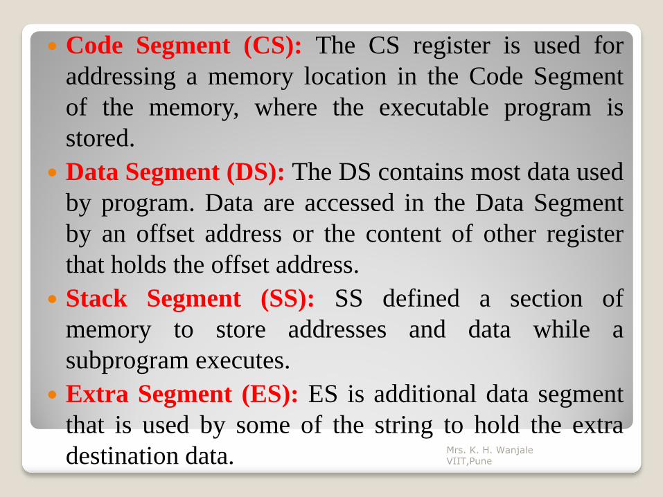
Code Segment (CS): The CS register is used for
addressing a memory location in the Code Segment
of the memory, where the executable program is
stored.
Data Segment (DS): The DS contains most data used
by program. Data are accessed in the Data Segment
by an offset address or the content of other register
that holds the offset address.
Stack Segment (SS): SS defined a section of
memory to store addresses and data while a
subprogram executes.
Extra Segment (ES): ES is additional data segment
that is used by some of the string to hold the extra
destination data.
Mrs. K. H. Wanjale VIIT,Pune
Instruction Pointer (IP)
In the BIU, the next register, below the segment
register is instruction pointer. The instruction pointer
(IP) holds the 16-bit address of the next code byte
within this code segment.
Mrs. K. H. Wanjale VIIT,Pune
The Execution Unit
The execution unit (EU) tells the BIU where to fetch instructions or data from, decodes instructions, and executes instructions.
The functional parts of the execution unit are control circuitry or system, instruction decoder, and Arithmetic logic unit (ALU).
Control circuitry to perform various internal operations.
A decoder in the EU translates instructions fetched from memory to generate different internal or external control signals that required performing the operation.
Mrs. K. H. Wanjale VIIT,Pune
The Execution Unit
The EU has a 16-bit ALU, which can perform
arithmetic operations such as add, subtract etc. and
logical operations such as AND, OR, XOR,
increment, decrement etc.
The functions of execution unit are:
◦ To tell BIU where to fetch the instructions or data from.
◦ To decode the instructions.
◦ To execute the instructions.
Mrs. K. H. Wanjale VIIT,Pune
UNIVERSITY QUESTIONS on 8086
Q.1)Define microprocessor. Give some features of
8086 microprocessor. [3]
Q.2) Enlist difference between 8086 and 80386.[3]
Q.3) How many segment registers are used by
8086?Mention their use.[3]
Mrs. K. H. Wanjale VIIT,Pune
Flag Registers of 8086
Flag Register of 8086
Mrs. K. H. Wanjale VIIT,Pune
Flag Registers of 8086 Flags Register determines the current state of the processor.
They are modified automatically by CPU after mathematical operations, this allows to determine the type of the result, and to determine conditions to transfer control to other parts of the program.
8086 has 9 flags and they are divided into two categories: ◦ Conditional Flags
◦ Control Flags
Mrs. K. H. Wanjale VIIT,Pune
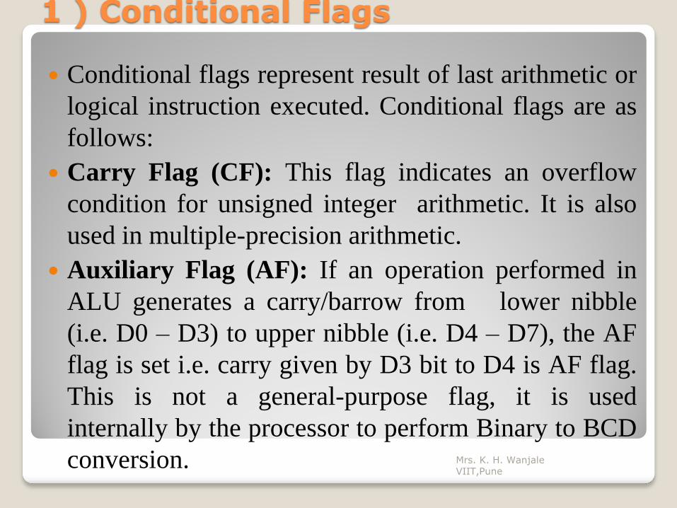
1 ) Conditional Flags Conditional flags represent result of last arithmetic or
logical instruction executed. Conditional flags are as
follows:
Carry Flag (CF): This flag indicates an overflow
condition for unsigned integer arithmetic. It is also
used in multiple-precision arithmetic.
Auxiliary Flag (AF): If an operation performed in
ALU generates a carry/barrow from lower nibble
(i.e. D0 – D3) to upper nibble (i.e. D4 – D7), the AF
flag is set i.e. carry given by D3 bit to D4 is AF flag.
This is not a general-purpose flag, it is used
internally by the processor to perform Binary to BCD
conversion.
Mrs. K. H. Wanjale VIIT,Pune
Parity Flag (PF): This flag is used to indicate the
parity of result. If lower order 8-bits of the result
contains even number of 1’s, the Parity Flag is set and
for odd number of 1’s, the Parity Flag is reset.
Zero Flag (ZF): It is set; if the result of arithmetic or
logical operation is zero else it is reset.
Sign Flag (SF): In sign magnitude format the sign of
number is indicated by MSB bit. If the result of
operation is negative, sign flag is set.
Overflow Flag (OF): It occurs when signed numbers
are added or subtracted. An OF indicates that the
result has exceeded the capacity of machine.
Mrs. K. H. Wanjale VIIT,Pune
Control Flags
Control flags are set or reset deliberately to control the
operations of the execution unit. Control flags are as follows:
Trap Flag (TP):
◦ It is used for single step control.
◦ It allows user to execute one instruction of a program at a
time for debugging.
◦ When trap flag is set, program can be run in single step
mode.
Interrupt Flag (IF):
◦ It is an interrupt enable/disable flag.
◦ If it is set, the maskable interrupt of 8086 is enabled and if it
is reset, the interrupt is disabled.
◦ It can be set by executing instruction sit and can be cleared
by executing CLI instruction.
Mrs. K. H. Wanjale VIIT,Pune
Direction Flag (DF)
◦ It is used in string operation.
◦ If it is set, string bytes are accessed from higher memory address to lower memory address.
◦ When it is reset, the string bytes are accessed from lower memory address to higher memory address.


![8086 Instruction Set...4 Assembly Language Microprocessors (A) Fall 2004 Hadassah College Dr. Martin Land Data Movement ⎯Scope BYTE PTR[1000]= memory byte at address 1000 …](https://static.documents.pub/doc/80x56/605163dedc83711eed1c02ad/8086-instruction-set-4-assembly-language-microprocessors-a-fall-2004-hadassah.jpg)


