Last Update: 7 November 2017 Front cover Introduction to Spine-Leaf Networking Designs Explains three-tier versus spine-leaf network architectures Details the advantages and disadvantages of three-tier and spine-leaf architectures Introduces Lenovo’s recommended spine-leaf switches Details the capacities of Lenovo’s recommended spine-leaf implementations William Nelson
Transcript
Last Update: 7 November 2017
Front cover
Introduction to Spine-Leaf Networking Designs
Explains three-tier versus spine-leaf network architectures
Details the advantages and disadvantages of three-tier and spine-leaf architectures
The traditional three-layer network topologies are losing momentum in the modern data center and are being supplanted by spine-leaf designs (also known as Clos designs after one of the original researchers, Charles Clos). This is even despite three-layer familiarity, scalability and ease of implementation.
Why is this happening? Organizations are seeking to maximize the function and utilization of their data centers leading to architecture optimized for software defined and cloud solutions. The spine-leaf architecture provides a strong base for the software defined data center optimizing the reliability and bandwidth available server communications.
This document describes the following:
� The traditional three-layer and spine-leaf architectures� The advantages and disadvantages of each architecture approach� Lenovo®’s spine-leaf solutions
This paper is for network architects and decision makers desiring to understand why spine-leaf designs are important to the modern data center and how Lenovo Networking products can be utilized in these designs.
At Lenovo Press, we bring together experts to produce technical publications around topics of importance to you, providing information and best practices for using Lenovo products and solutions to solve IT challenges.
See a list of our most recent publications at the Lenovo Press web site:
Do you have the latest version? We update our papers from time to time, so check whether you have the latest version of this document by clicking the Check for Updates button on the front page of the PDF. Pressing this button will take you to a web page that will tell you if you are reading the latest version of the document and give you a link to the latest if needed. While you’re there, you can also sign up to get notified via email whenever we make an update.
The overall network performance is highly dependent upon the design approach that is utilized. These approaches can be optimized for either north-south or east-west traffic flows. The following three-tier and spine-leaf architectures are two classic approaches utilized to optimize designs for north-south and east-west traffic respectively.
Three-tier architecture
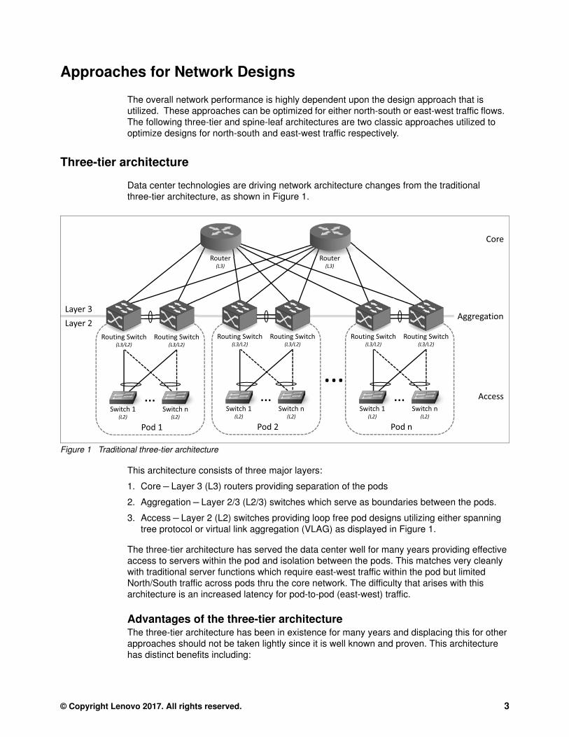
Data center technologies are driving network architecture changes from the traditional three-tier architecture, as shown in Figure 1.
Figure 1 Traditional three-tier architecture
This architecture consists of three major layers:
1. Core – Layer 3 (L3) routers providing separation of the pods
2. Aggregation – Layer 2/3 (L2/3) switches which serve as boundaries between the pods.
3. Access – Layer 2 (L2) switches providing loop free pod designs utilizing either spanning tree protocol or virtual link aggregation (VLAG) as displayed in Figure 1.
The three-tier architecture has served the data center well for many years providing effective access to servers within the pod and isolation between the pods. This matches very cleanly with traditional server functions which require east-west traffic within the pod but limited North/South traffic across pods thru the core network. The difficulty that arises with this architecture is an increased latency for pod-to-pod (east-west) traffic.
Advantages of the three-tier architectureThe three-tier architecture has been in existence for many years and displacing this for other approaches should not be taken lightly since it is well known and proven. This architecture has distinct benefits including:
� Availability – if a pod is down due to equipment or some other failure, it can be easily isolated to a branch (pod) without affecting other branches (pods)
� Security – processes and data can be isolated in pods limiting exposure risks
� Performance – traffic within the pod is reduced so oversubscription is minimized
� Scalability – if a pod becomes oversubscribed, it is a simple task to add another pod and load-balance traffic across them and improving application performance
� Simplicity –network issues caused by leaf devices are simplified because the number of devices in each branch are limited
Disadvantages of the three-tier architectureAs previously stated, software defined infrastructures are requiring changes in the traditional network architecture demanding expanded east-west traffic flows. The major software defined applications driving this are virtualization and convergence.
� Virtualization requires moving workloads across multiple devices which share common backend information.
� Convergence requires storage traffic between devices on the same network segment.
These applications also drive increased bandwidth utilization which is difficult to expand across the multiple layered network devices in the three-tier architecture. This leads to the core network devices being very expensive high speed links.
Spine-leaf architecture
New data centers are now being designed for cloud architectures with larger east-west traffic domains. This drives the need for a network architectures with an expanded flat east-west domain like spine-leaf as shown in Figure 2 on page 5. Solutions like VMware NSX, OpenStack and others that distribute workloads to virtual machines running on many overlay networks running on top of a traditional underlay (physical) network require mobility across the flatter east-west domain.
4 Introduction to Spine-Leaf Networking Designs
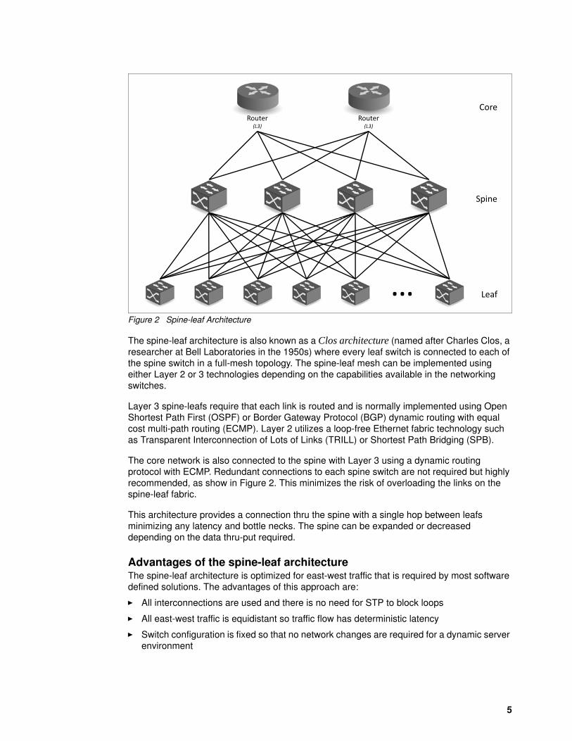
Figure 2 Spine-leaf Architecture
The spine-leaf architecture is also known as a Clos architecture (named after Charles Clos, a researcher at Bell Laboratories in the 1950s) where every leaf switch is connected to each of the spine switch in a full-mesh topology. The spine-leaf mesh can be implemented using either Layer 2 or 3 technologies depending on the capabilities available in the networking switches.
Layer 3 spine-leafs require that each link is routed and is normally implemented using Open Shortest Path First (OSPF) or Border Gateway Protocol (BGP) dynamic routing with equal cost multi-path routing (ECMP). Layer 2 utilizes a loop-free Ethernet fabric technology such as Transparent Interconnection of Lots of Links (TRILL) or Shortest Path Bridging (SPB).
The core network is also connected to the spine with Layer 3 using a dynamic routing protocol with ECMP. Redundant connections to each spine switch are not required but highly recommended, as show in Figure 2. This minimizes the risk of overloading the links on the spine-leaf fabric.
This architecture provides a connection thru the spine with a single hop between leafs minimizing any latency and bottle necks. The spine can be expanded or decreased depending on the data thru-put required.
Advantages of the spine-leaf architectureThe spine-leaf architecture is optimized for east-west traffic that is required by most software defined solutions. The advantages of this approach are:
� All interconnections are used and there is no need for STP to block loops
� All east-west traffic is equidistant so traffic flow has deterministic latency
� Switch configuration is fixed so that no network changes are required for a dynamic server environment
Router(L3)
Router(L3)
Core
� Leaf
Spine
5
Disadvantages of the spine-leaf architectureThe spine-leaf architecture is not without concerns as listed below:
� The leading concern is the amount of cables and network equipment required to scale the bandwidth since each leaf must be connected to every spine device. This can lead to more expensive spine switches with high port counts.
� The number of hosts that can be supported can be limited due to spine port counts restricting the number of leaf switch connections.
� Oversubscription of the spine-leaf connections can occur due to a limited number of spine connections available on the leaf switches (typically 4 to 6). Generally, no more than a 5:1 oversubscription ratio between the leaf and spine is considered acceptable but this is highly dependent upon the amount of traffic in your particular environment.
� Oversubscription of the links out of the spine-leaf domain to the core should also be considered. Since this architecture is optimized for east-west traffic as opposed to north-south, oversubscriptions of 100:1 may be considered acceptable.
Lenovo spine-leaf
The spine-leaf architecture provides a loop free mesh between the spine and the leaf switches. This can be accomplished using either Layer 2 or 3 designs. Lenovo provides solutions for small two switch Layer 2 spines and expanded multi-switch Layer 3 spines utilizing either Cloud Network Operating System (CNOS) or Enterprise Network Operating System (ENOS).
The following sections detail Lenovo’s recommendation for spine-leaf switches, and Layer 2 and 3 designs.
A table summarizing the scaling of Lenovo's spine-leaf solutions is also provided in “Appendix: Lenovo spine-leaf capacities” on page 22 as a convenient reference.
Lenovo Layer 2 spine-leaf architecture
Lenovo implements the Layer 2 spine-leaf network utilizing VLAG to provide a non-blocking loop free design as show in Figure 3 on page 7. Every spine-leaf switch is aggregated in pairs of switches utilizing 100 Gbps spine links providing a 400 Gbps spine with very low congestion. This solution offers the ability to connect to redundant server NICs using bonding with LAG or MAC address load balancing as well as utilizing the NICs independently.
6 Introduction to Spine-Leaf Networking Designs
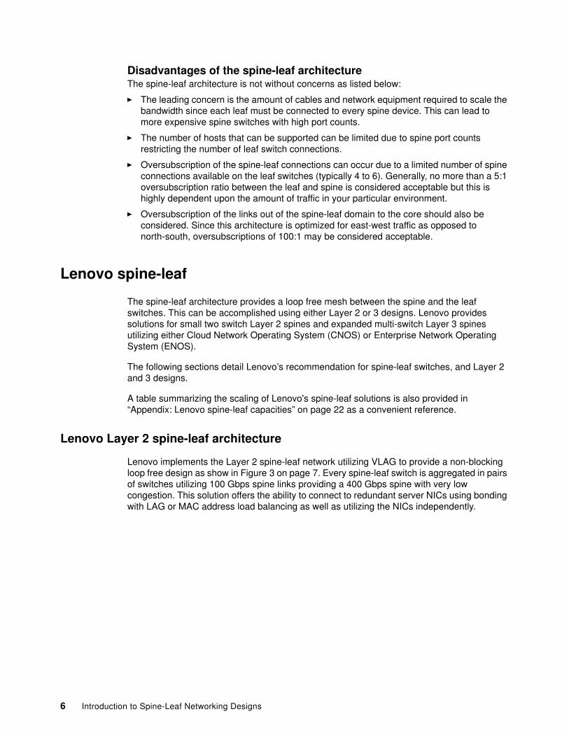
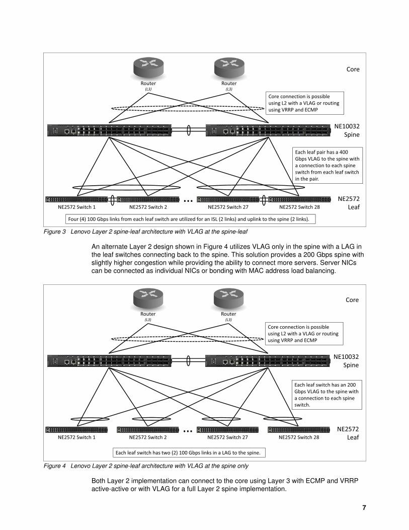
Figure 3 Lenovo Layer 2 spine-leaf architecture with VLAG at the spine-leaf
An alternate Layer 2 design shown in Figure 4 utilizes VLAG only in the spine with a LAG in the leaf switches connecting back to the spine. This solution provides a 200 Gbps spine with slightly higher congestion while providing the ability to connect more servers. Server NICs can be connected as individual NICs or bonding with MAC address load balancing.
Figure 4 Lenovo Layer 2 spine-leaf architecture with VLAG at the spine only
Both Layer 2 implementation can connect to the core using Layer 3 with ECMP and VRRP active-active or with VLAG for a full Layer 2 spine implementation.
Router(L3)
Router(L3)
NE2572Leaf
�
Each leaf pair has a 400 Gbps VLAG to the spine with a connection to each spine switch from each leaf switch in the pair.
Core connection is possible using L2 with a VLAG or routing using VRRP and ECMP
Core
Four (4) 100 Gbps links from each leaf switch are utilized for an ISL (2 links) and uplink to the spine (2 links).
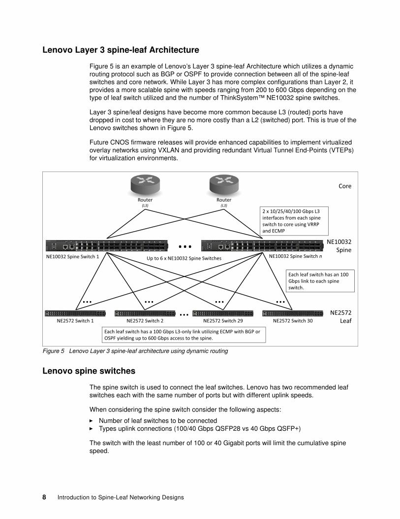
Figure 5 is an example of Lenovo’s Layer 3 spine-leaf Architecture which utilizes a dynamic routing protocol such as BGP or OSPF to provide connection between all of the spine-leaf switches and core network. While Layer 3 has more complex configurations than Layer 2, it provides a more scalable spine with speeds ranging from 200 to 600 Gbps depending on the type of leaf switch utilized and the number of ThinkSystem™ NE10032 spine switches.
Layer 3 spine/leaf designs have become more common because L3 (routed) ports have dropped in cost to where they are no more costly than a L2 (switched) port. This is true of the Lenovo switches shown in Figure 5.
Future CNOS firmware releases will provide enhanced capabilities to implement virtualized overlay networks using VXLAN and providing redundant Virtual Tunnel End-Points (VTEPs) for virtualization environments.
Figure 5 Lenovo Layer 3 spine-leaf architecture using dynamic routing
Lenovo spine switches
The spine switch is used to connect the leaf switches. Lenovo has two recommended leaf switches each with the same number of ports but with different uplink speeds.
When considering the spine switch consider the following aspects:
� Number of leaf switches to be connected� Types uplink connections (100/40 Gbps QSFP28 vs 40 Gbps QSFP+)
The switch with the least number of 100 or 40 Gigabit ports will limit the cumulative spine speed.
Router(L3)
Router(L3)
NE2572Leaf
Each leaf switch has an 100 Gbps link to each spine switch.
2 x 10/25/40/100 Gbps L3 interfaces from each spine switch to core using VRRP and ECMP
Core
Each leaf switch has a 100 Gbps L3-only link utilizing ECMP with BGP or OSPF yielding up to 600 Gbps access to the spine.
� � � �
NE10032 Spine Switch 1 NE10032 Spine Switch nUp to 6 x NE10032 Spine Switches
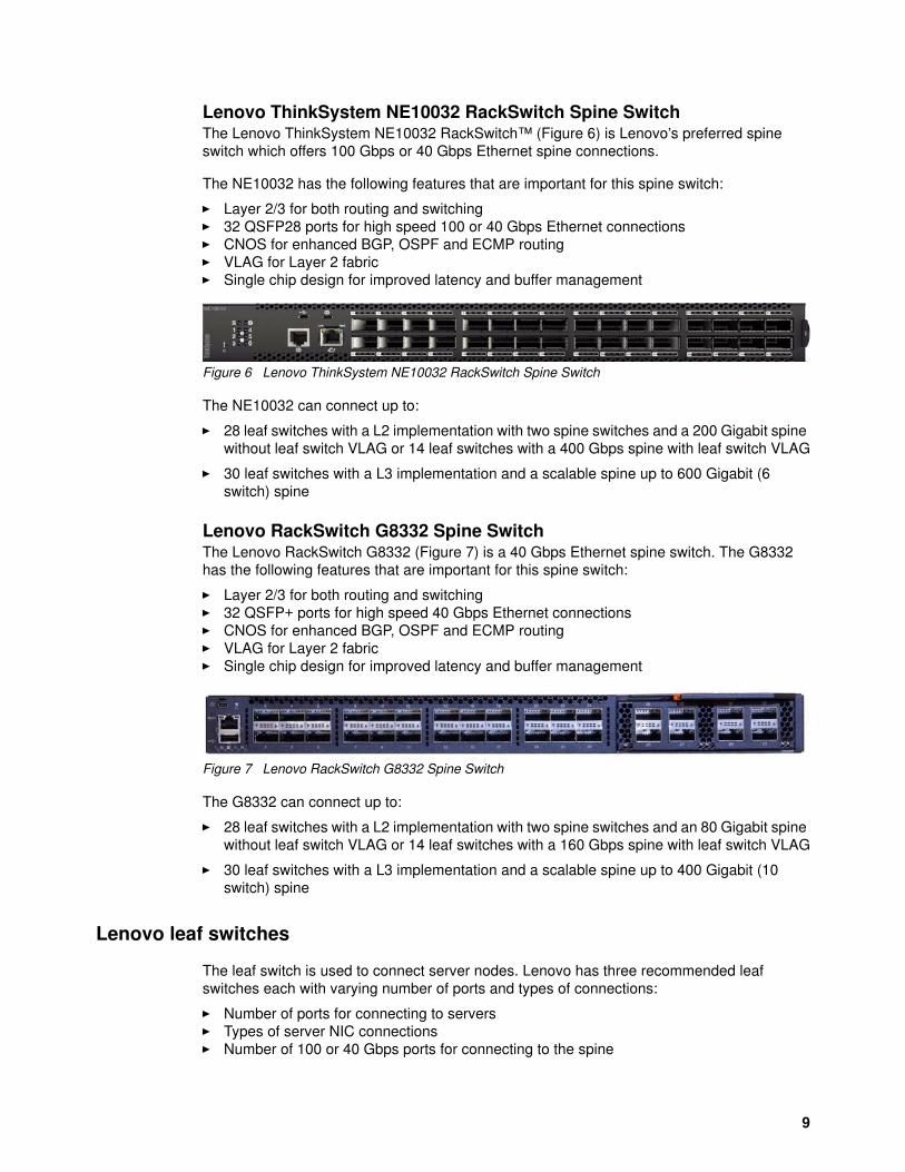
Lenovo ThinkSystem NE10032 RackSwitch Spine SwitchThe Lenovo ThinkSystem NE10032 RackSwitch™ (Figure 6) is Lenovo’s preferred spine switch which offers 100 Gbps or 40 Gbps Ethernet spine connections.
The NE10032 has the following features that are important for this spine switch:
� Layer 2/3 for both routing and switching� 32 QSFP28 ports for high speed 100 or 40 Gbps Ethernet connections� CNOS for enhanced BGP, OSPF and ECMP routing� VLAG for Layer 2 fabric� Single chip design for improved latency and buffer management
� 28 leaf switches with a L2 implementation with two spine switches and a 200 Gigabit spine without leaf switch VLAG or 14 leaf switches with a 400 Gbps spine with leaf switch VLAG
� 30 leaf switches with a L3 implementation and a scalable spine up to 600 Gigabit (6 switch) spine
Lenovo RackSwitch G8332 Spine SwitchThe Lenovo RackSwitch G8332 (Figure 7) is a 40 Gbps Ethernet spine switch. The G8332 has the following features that are important for this spine switch:
� Layer 2/3 for both routing and switching� 32 QSFP+ ports for high speed 40 Gbps Ethernet connections� CNOS for enhanced BGP, OSPF and ECMP routing� VLAG for Layer 2 fabric� Single chip design for improved latency and buffer management
Figure 7 Lenovo RackSwitch G8332 Spine Switch
The G8332 can connect up to:
� 28 leaf switches with a L2 implementation with two spine switches and an 80 Gigabit spine without leaf switch VLAG or 14 leaf switches with a 160 Gbps spine with leaf switch VLAG
� 30 leaf switches with a L3 implementation and a scalable spine up to 400 Gigabit (10 switch) spine
Lenovo leaf switches
The leaf switch is used to connect server nodes. Lenovo has three recommended leaf switches each with varying number of ports and types of connections:
� Number of ports for connecting to servers� Types of server NIC connections� Number of 100 or 40 Gbps ports for connecting to the spine
9
When considering mixed types of leaf switches, the switch with the least number of 100 or 40 Gigabit ports will limit the cumulative spine speed.
Leaf switches described in this section:
� “Lenovo ThinkSystem NE2572 RackSwitch Leaf Switch”� “Lenovo RackSwitch G8272 Leaf Switch” on page 12� “Lenovo RackSwitch G8296 Leaf Switch” on page 15� “Lenovo EN4093R Leaf Switch for Flex System” on page 18
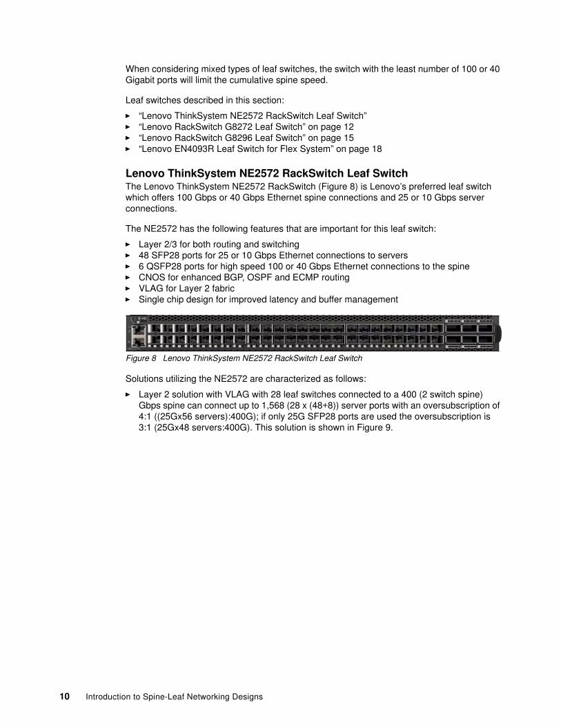
Lenovo ThinkSystem NE2572 RackSwitch Leaf SwitchThe Lenovo ThinkSystem NE2572 RackSwitch (Figure 8) is Lenovo’s preferred leaf switch which offers 100 Gbps or 40 Gbps Ethernet spine connections and 25 or 10 Gbps server connections.
The NE2572 has the following features that are important for this leaf switch:
� Layer 2/3 for both routing and switching� 48 SFP28 ports for 25 or 10 Gbps Ethernet connections to servers� 6 QSFP28 ports for high speed 100 or 40 Gbps Ethernet connections to the spine� CNOS for enhanced BGP, OSPF and ECMP routing� VLAG for Layer 2 fabric� Single chip design for improved latency and buffer management
Solutions utilizing the NE2572 are characterized as follows:
� Layer 2 solution with VLAG with 28 leaf switches connected to a 400 (2 switch spine) Gbps spine can connect up to 1,568 (28 x (48+8)) server ports with an oversubscription of 4:1 ((25Gx56 servers):400G); if only 25G SFP28 ports are used the oversubscription is 3:1 (25Gx48 servers:400G). This solution is shown in Figure 9.
10 Introduction to Spine-Leaf Networking Designs
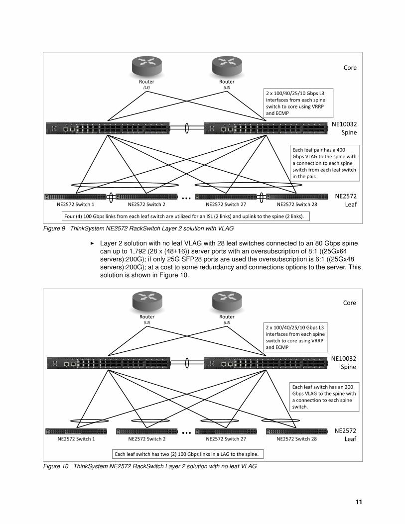
Figure 9 ThinkSystem NE2572 RackSwitch Layer 2 solution with VLAG
� Layer 2 solution with no leaf VLAG with 28 leaf switches connected to an 80 Gbps spine can up to 1,792 (28 x (48+16)) server ports with an oversubscription of 8:1 ((25Gx64 servers):200G); if only 25G SFP28 ports are used the oversubscription is 6:1 ((25Gx48 servers):200G); at a cost to some redundancy and connections options to the server. This solution is shown in Figure 10.
Figure 10 ThinkSystem NE2572 RackSwitch Layer 2 solution with no leaf VLAG
Router(L3)
Router(L3)
NE10032Spine
Each leaf pair has a 400 Gbps VLAG to the spine with a connection to each spine switch from each leaf switch in the pair.
2 x 100/40/25/10 Gbps L3 interfaces from each spine switch to core using VRRP and ECMP
Core
Four (4) 100 Gbps links from each leaf switch are utilized for an ISL (2 links) and uplink to the spine (2 links).
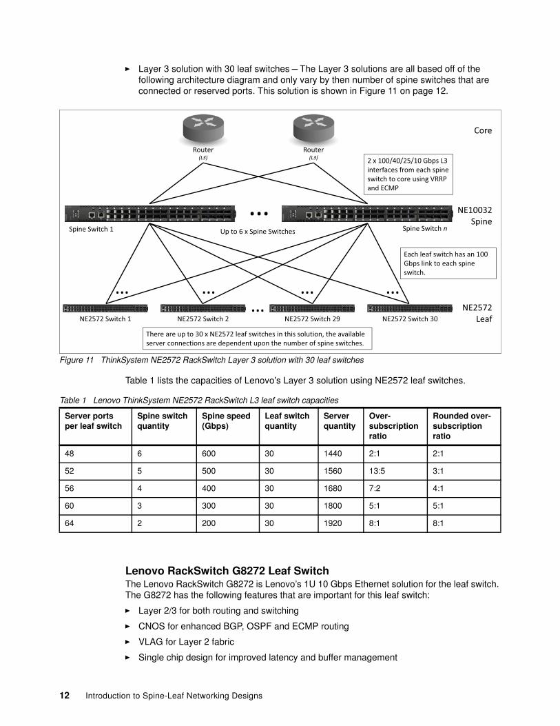
� Layer 3 solution with 30 leaf switches – The Layer 3 solutions are all based off of the following architecture diagram and only vary by then number of spine switches that are connected or reserved ports. This solution is shown in Figure 11 on page 12.
Lenovo RackSwitch G8272 Leaf SwitchThe Lenovo RackSwitch G8272 is Lenovo’s 1U 10 Gbps Ethernet solution for the leaf switch. The G8272 has the following features that are important for this leaf switch:
� Layer 2/3 for both routing and switching
� CNOS for enhanced BGP, OSPF and ECMP routing
� VLAG for Layer 2 fabric
� Single chip design for improved latency and buffer management
Router(L3)
Router(L3)
Each leaf switch has an 100 Gbps link to each spine switch.
Core
There are up to 30 x NE2572 leaf switches in this solution, the available server connections are dependent upon the number of spine switches.
� � � �
Spine Switch 1 Spine Switch nUp to 6 x Spine Switches
NE10032Spine
�
2 x 100/40/25/10 Gbps L3 interfaces from each spine switch to core using VRRP and ECMP
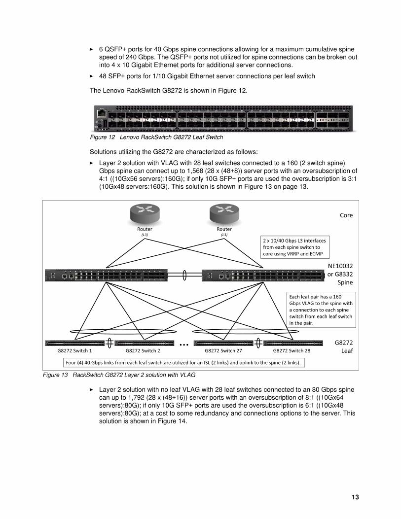
� 6 QSFP+ ports for 40 Gbps spine connections allowing for a maximum cumulative spine speed of 240 Gbps. The QSFP+ ports not utilized for spine connections can be broken out into 4 x 10 Gigabit Ethernet ports for additional server connections.
� 48 SFP+ ports for 1/10 Gigabit Ethernet server connections per leaf switch
The Lenovo RackSwitch G8272 is shown in Figure 12.
Figure 12 Lenovo RackSwitch G8272 Leaf Switch
Solutions utilizing the G8272 are characterized as follows:
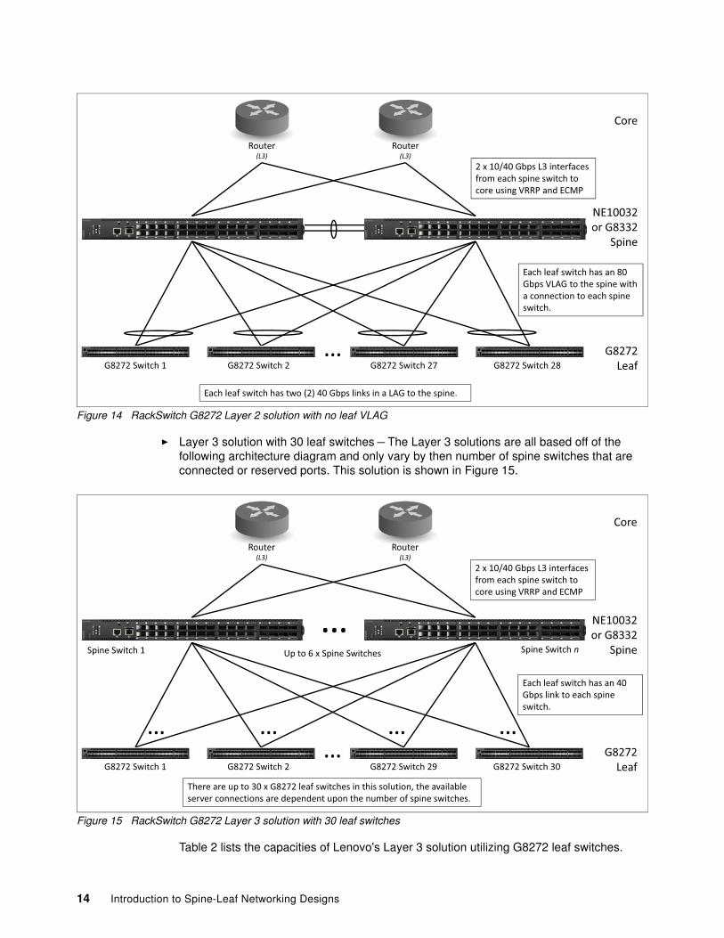
� Layer 2 solution with VLAG with 28 leaf switches connected to a 160 (2 switch spine) Gbps spine can connect up to 1,568 (28 x (48+8)) server ports with an oversubscription of 4:1 ((10Gx56 servers):160G); if only 10G SFP+ ports are used the oversubscription is 3:1 (10Gx48 servers:160G). This solution is shown in Figure 13 on page 13.
Figure 13 RackSwitch G8272 Layer 2 solution with VLAG
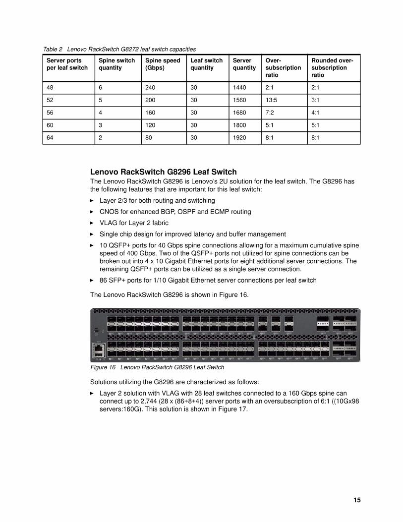
� Layer 2 solution with no leaf VLAG with 28 leaf switches connected to an 80 Gbps spine can up to 1,792 (28 x (48+16)) server ports with an oversubscription of 8:1 ((10Gx64 servers):80G); if only 10G SFP+ ports are used the oversubscription is 6:1 ((10Gx48 servers):80G); at a cost to some redundancy and connections options to the server. This solution is shown in Figure 14.
Each leaf pair has a 160 Gbps VLAG to the spine with a connection to each spine switch from each leaf switch in the pair.
2 x 10/40 Gbps L3 interfaces from each spine switch to core using VRRP and ECMP
Core
Four (4) 40 Gbps links from each leaf switch are utilized for an ISL (2 links) and uplink to the spine (2 links).
13
Figure 14 RackSwitch G8272 Layer 2 solution with no leaf VLAG
� Layer 3 solution with 30 leaf switches – The Layer 3 solutions are all based off of the following architecture diagram and only vary by then number of spine switches that are connected or reserved ports. This solution is shown in Figure 15.
Lenovo RackSwitch G8296 Leaf SwitchThe Lenovo RackSwitch G8296 is Lenovo’s 2U solution for the leaf switch. The G8296 has the following features that are important for this leaf switch:
� Layer 2/3 for both routing and switching
� CNOS for enhanced BGP, OSPF and ECMP routing
� VLAG for Layer 2 fabric
� Single chip design for improved latency and buffer management
� 10 QSFP+ ports for 40 Gbps spine connections allowing for a maximum cumulative spine speed of 400 Gbps. Two of the QSFP+ ports not utilized for spine connections can be broken out into 4 x 10 Gigabit Ethernet ports for eight additional server connections. The remaining QSFP+ ports can be utilized as a single server connection.
� 86 SFP+ ports for 1/10 Gigabit Ethernet server connections per leaf switch
The Lenovo RackSwitch G8296 is shown in Figure 16.
Figure 16 Lenovo RackSwitch G8296 Leaf Switch
Solutions utilizing the G8296 are characterized as follows:
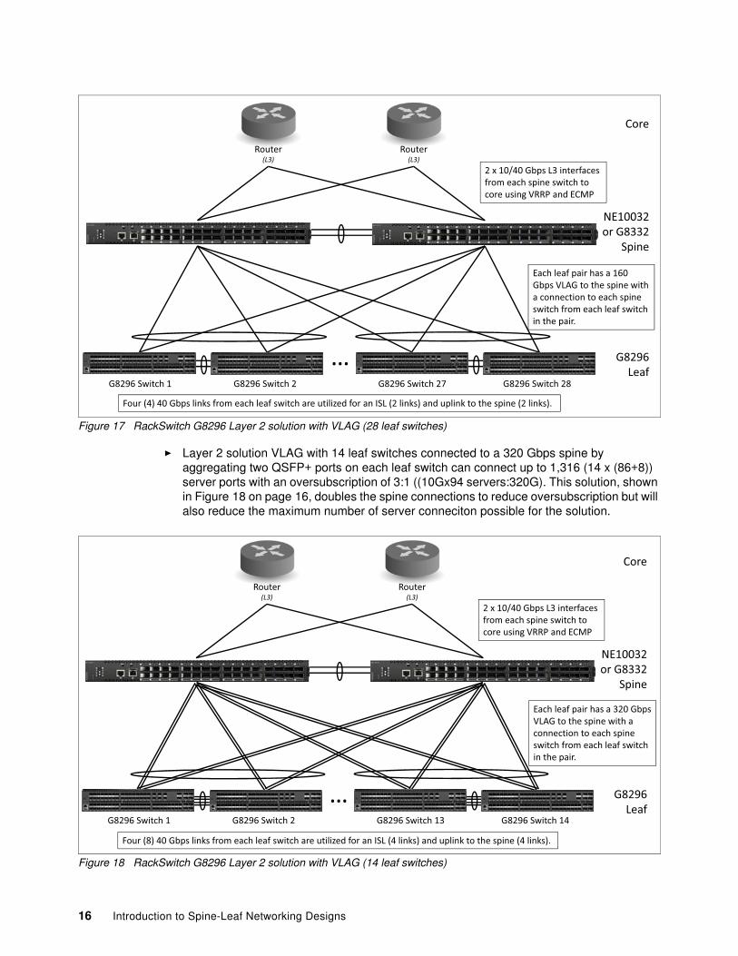
� Layer 2 solution with VLAG with 28 leaf switches connected to a 160 Gbps spine can connect up to 2,744 (28 x (86+8+4)) server ports with an oversubscription of 6:1 ((10Gx98 servers:160G). This solution is shown in Figure 17.
� Layer 2 solution VLAG with 14 leaf switches connected to a 320 Gbps spine by aggregating two QSFP+ ports on each leaf switch can connect up to 1,316 (14 x (86+8)) server ports with an oversubscription of 3:1 ((10Gx94 servers:320G). This solution, shown in Figure 18 on page 16, doubles the spine connections to reduce oversubscription but will also reduce the maximum number of server conneciton possible for the solution.
Each leaf pair has a 320 Gbps VLAG to the spine with a connection to each spine switch from each leaf switch in the pair.
2 x 10/40 Gbps L3 interfaces from each spine switch to core using VRRP and ECMP
Core
Four (8) 40 Gbps links from each leaf switch are utilized for an ISL (4 links) and uplink to the spine (4 links).
NE10032 or G8332
Spine
16 Introduction to Spine-Leaf Networking Designs
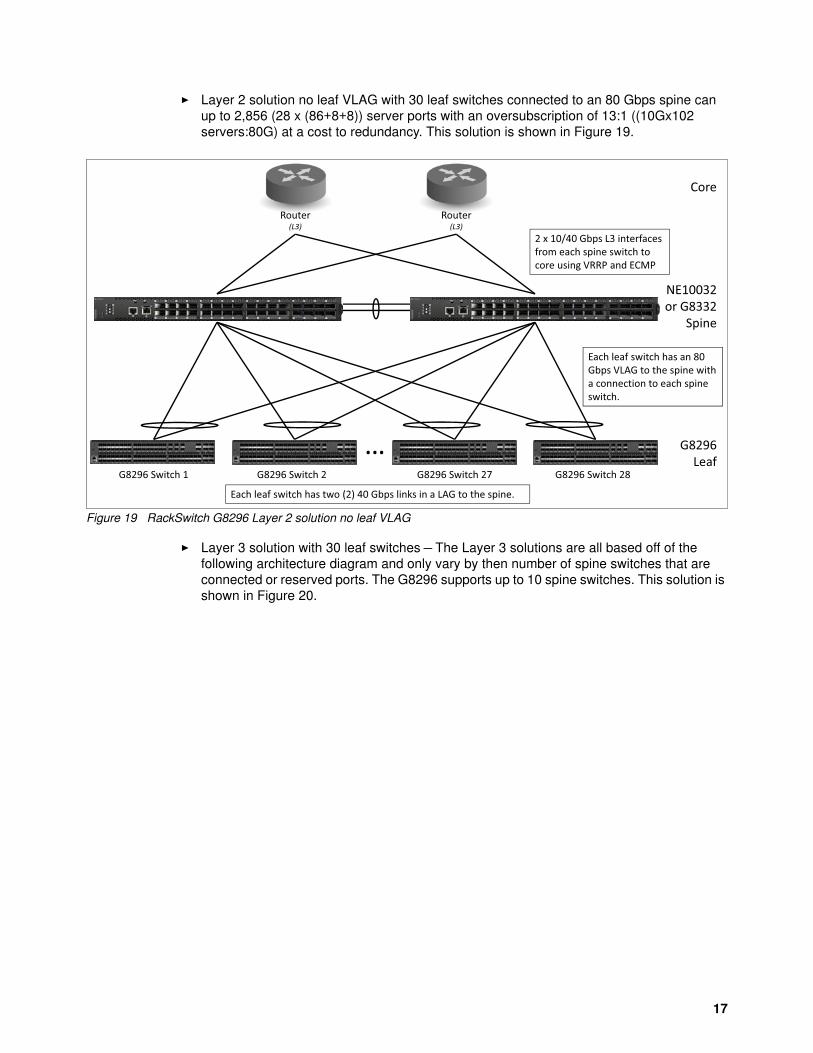
� Layer 2 solution no leaf VLAG with 30 leaf switches connected to an 80 Gbps spine can up to 2,856 (28 x (86+8+8)) server ports with an oversubscription of 13:1 ((10Gx102 servers:80G) at a cost to redundancy. This solution is shown in Figure 19.
Figure 19 RackSwitch G8296 Layer 2 solution no leaf VLAG
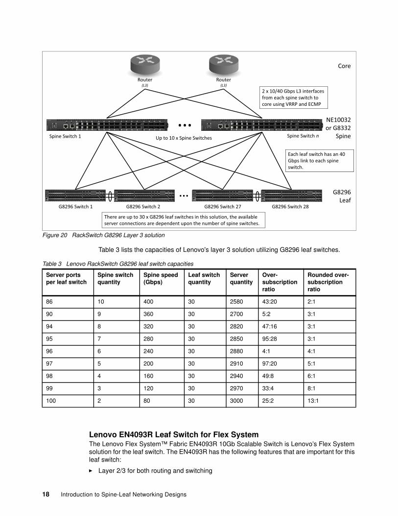
� Layer 3 solution with 30 leaf switches – The Layer 3 solutions are all based off of the following architecture diagram and only vary by then number of spine switches that are connected or reserved ports. The G8296 supports up to 10 spine switches. This solution is shown in Figure 20.
Router(L3)
Router(L3)
Each leaf switch has an 80 Gbps VLAG to the spine with a connection to each spine switch.
2 x 10/40 Gbps L3 interfaces from each spine switch to core using VRRP and ECMP
Core
Each leaf switch has two (2) 40 Gbps links in a LAG to the spine.
Lenovo EN4093R Leaf Switch for Flex SystemThe Lenovo Flex System™ Fabric EN4093R 10Gb Scalable Switch is Lenovo’s Flex System solution for the leaf switch. The EN4093R has the following features that are important for this leaf switch:
2 x 10/40 Gbps L3 interfaces from each spine switch to core using VRRP and ECMP
Core
There are up to 30 x G8296 leaf switches in this solution, the available server connections are dependent upon the number of spine switches.
Each leaf switch has an 40 Gbps link to each spine switch.
Spine Switch 1 Spine Switch nUp to 10 x Spine Switches
NE10032 or G8332
Spine
�
Server portsper leaf switch
Spine switchquantity
Spine speed(Gbps)
Leaf switchquantity
Serverquantity
Over-subscriptionratio
Rounded over-subscriptionratio
86 10 400 30 2580 43:20 2:1
90 9 360 30 2700 5:2 3:1
94 8 320 30 2820 47:16 3:1
95 7 280 30 2850 95:28 3:1
96 6 240 30 2880 4:1 4:1
97 5 200 30 2910 97:20 5:1
98 4 160 30 2940 49:8 6:1
99 3 120 30 2970 33:4 8:1
100 2 80 30 3000 25:2 13:1
18 Introduction to Spine-Leaf Networking Designs
� ENOS with BGP, OSPF and ECMP routing
� VLAG for Layer 2 fabric
� Single chip design for improved latency and buffer management
� 2 QSFP+ ports for 40 Gbps spine connections allowing for a maximum cumulative spine speed of 80 Gbps.
� 14 dedicated server facing ports
� 14 SFP+ ports for 1/10 Gigabit external Ethernet server connections and an Inter-Switch Link (ISL) for use with VLAG
The Lenovo Flex System Fabric EN4093R 10Gb Scalable Switch is shown in Figure 21.
Figure 21 Lenovo Flex System Fabric EN4093R 10Gb Scalable Switch
Solutions utilizing the Flex System Chassis and the EN4093R have some limitations as compared to TOR based solutions. The main limitation is the limited number of 40 Gbps ports restricting this solution to two spine switches. There is also a limited number of servers that can be connected due to the hard wired connections to the Flex System server nodes.
Solutions utilizing the EN4093R are characterized as follows:
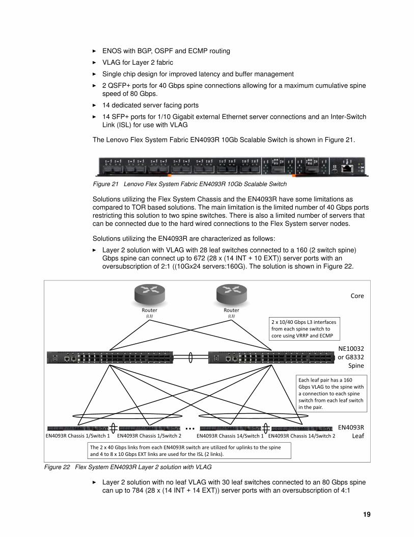
� Layer 2 solution with VLAG with 28 leaf switches connected to a 160 (2 switch spine) Gbps spine can connect up to 672 (28 x (14 INT + 10 EXT)) server ports with an oversubscription of 2:1 ((10Gx24 servers:160G). The solution is shown in Figure 22.
Figure 22 Flex System EN4093R Layer 2 solution with VLAG
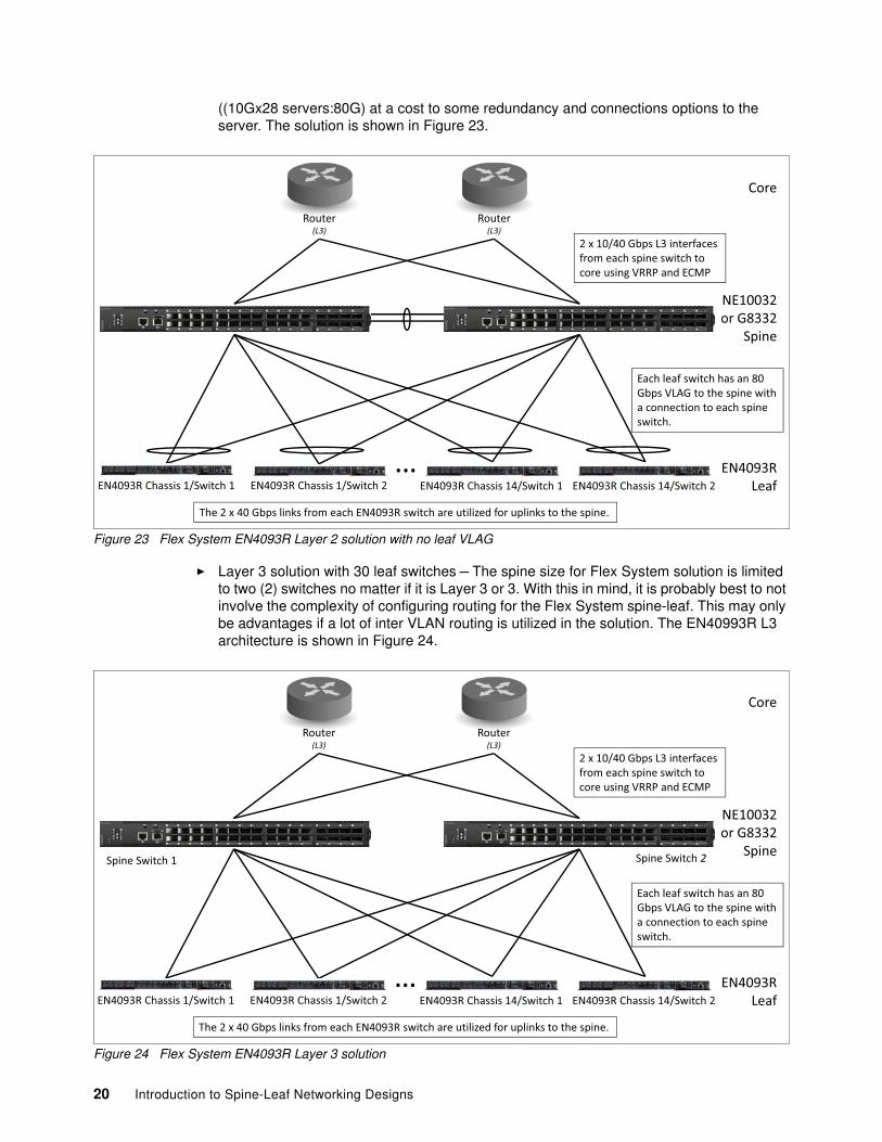
� Layer 2 solution with no leaf VLAG with 30 leaf switches connected to an 80 Gbps spine can up to 784 (28 x (14 INT + 14 EXT)) server ports with an oversubscription of 4:1
((10Gx28 servers:80G) at a cost to some redundancy and connections options to the server. The solution is shown in Figure 23.
Figure 23 Flex System EN4093R Layer 2 solution with no leaf VLAG
� Layer 3 solution with 30 leaf switches – The spine size for Flex System solution is limited to two (2) switches no matter if it is Layer 3 or 3. With this in mind, it is probably best to not involve the complexity of configuring routing for the Flex System spine-leaf. This may only be advantages if a lot of inter VLAN routing is utilized in the solution. The EN40993R L3 architecture is shown in Figure 24.
Each leaf switch has an 80 Gbps VLAG to the spine with a connection to each spine switch.
Spine Switch 1 Spine Switch 2
NE10032 or G8332
Spine
20 Introduction to Spine-Leaf Networking Designs
The connected ports are as follows:
– 80 Gbps spine (2 switch spine) can connect up to 784 (28 x (14 INT + 14 EXT)) server ports with an oversubscription of 4:1 ((10Gx28 servers:80G)
Conclusion
Lenovo’s Layer 3 spine-leaf architecture provides the best oversubscription ratios with the highest number of server ports. This architecture also provides the ability to connect thousands of servers with low latency single hop connections between the leaf switches. These connections are made over a high speed spine with low congestion as indicated by the low oversubscription numbers. Lenovo’s Cloud Network Operating System (CNOS) also targets Layer 3 routing with BGP and OSPF routing protocols tuned for optimal performance.
With lower numbers of servers, Lenovo’s simple Layer 2 spine-leaf architecture provides good capacities without the complexity of Layer 3 configurations. The Layer 2 solution can also be greatly simplified using Q-in-Q tunneling so that no VLAN configuration is required.
In conclusion, Lenovo’s spine-leaf Architectures provide both Layer 2 and Layer 3 solutions with high capacities and low congestion.
21
d
-o
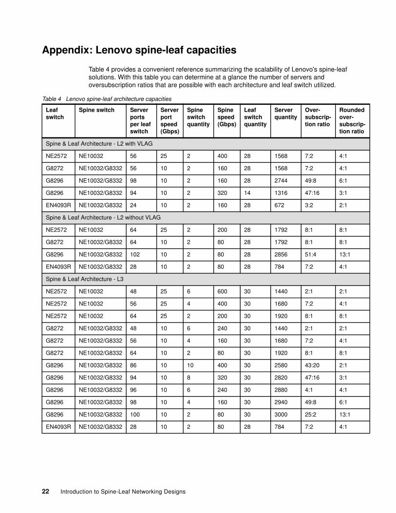
Appendix: Lenovo spine-leaf capacities
Table 4 provides a convenient reference summarizing the scalability of Lenovo's spine-leaf solutions. With this table you can determine at a glance the number of servers and oversubscription ratios that are possible with each architecture and leaf switch utilized.
TRILL Transparent Interconnection of Lots of Links
TOR Top Of Rack
VLAG Virtual Link Aggregation
VRRP Virtual Router Redundancy Protocol
Change history
November 7 update:
� Added the ThinkSystem NE10032 100 GbE spine switch
� Added the ThinkSystem NE2572 25 GbE leaf switch
Author
William Nelson is a Worldwide Technical Sales Leader for Lenovo Networking. He joined Lenovo from IBM and BNT® and has over 30 years of networking experience. He was one of the four founders of BNT and an early member of Centillion Networks and Alteon Web Systems. He is an evangelist for Lenovo's Networking products to the sales and customer communities and is the key voice of the customer to the networking product and engineering teams. Bill graduated from Virginia Tech with a BS in Biochemistry and University of Maryland with a BS in Computer Science.
Thanks to the following people for their contributions to this project:
� Jim Whitten, WW Product Marketing Manager for Lenovo Networking
� David Watts, Lenovo Press
23
Notices
Lenovo may not offer the products, services, or features discussed in this document in all countries. Consult your local Lenovo representative for information on the products and services currently available in your area. Any reference to a Lenovo product, program, or service is not intended to state or imply that only that Lenovo product, program, or service may be used. Any functionally equivalent product, program, or service that does not infringe any Lenovo intellectual property right may be used instead. However, it is the user's responsibility to evaluate and verify the operation of any other product, program, or service.
Lenovo may have patents or pending patent applications covering subject matter described in this document. The furnishing of this document does not give you any license to these patents. You can send license inquiries, in writing, to:
Lenovo (United States), Inc.1009 Think Place - Building OneMorrisville, NC 27560U.S.A.Attention: Lenovo Director of Licensing
LENOVO PROVIDES THIS PUBLICATION “AS IS” WITHOUT WARRANTY OF ANY KIND, EITHER EXPRESS OR IMPLIED, INCLUDING, BUT NOT LIMITED TO, THE IMPLIED WARRANTIES OF NON-INFRINGEMENT, MERCHANTABILITY OR FITNESS FOR A PARTICULAR PURPOSE. Some jurisdictions do not allow disclaimer of express or implied warranties in certain transactions, therefore, this statement may not apply to you.
This information could include technical inaccuracies or typographical errors. Changes are periodically made to the information herein; these changes will be incorporated in new editions of the publication. Lenovo may make improvements and/or changes in the product(s) and/or the program(s) described in this publication at any time without notice.
The products described in this document are not intended for use in implantation or other life support applications where malfunction may result in injury or death to persons. The information contained in this document does not affect or change Lenovo product specifications or warranties. Nothing in this document shall operate as an express or implied license or indemnity under the intellectual property rights of Lenovo or third parties. All information contained in this document was obtained in specific environments and is presented as an illustration. The result obtained in other operating environments may vary.
Lenovo may use or distribute any of the information you supply in any way it believes appropriate without incurring any obligation to you.
Any references in this publication to non-Lenovo Web sites are provided for convenience only and do not in any manner serve as an endorsement of those Web sites. The materials at those Web sites are not part of the materials for this Lenovo product, and use of those Web sites is at your own risk.
Any performance data contained herein was determined in a controlled environment. Therefore, the result obtained in other operating environments may vary significantly. Some measurements may have been made on development-level systems and there is no guarantee that these measurements will be the same on generally available systems. Furthermore, some measurements may have been estimated through extrapolation. Actual results may vary. Users of this document should verify the applicable data for their specific environment.
This document was created or updated on November 10, 2017.
Send us your comments via the Rate & Provide Feedback form found athttp://lenovopress.com/lp0573
Trademarks
Lenovo, the Lenovo logo, and For Those Who Do are trademarks or registered trademarks of Lenovo in the United States, other countries, or both. These and other Lenovo trademarked terms are marked on their first occurrence in this information with the appropriate symbol (® or ™), indicating US registered or common law trademarks owned by Lenovo at the time this information was published. Such trademarks may also be registered or common law trademarks in other countries. A current list of Lenovo trademarks is available on the Web at http://www.lenovo.com/legal/copytrade.html.
The following terms are trademarks of Lenovo in the United States, other countries, or both:
BNT®Flex System™
Lenovo®RackSwitch™
Lenovo(logo)®ThinkSystem™
The following terms are trademarks of other companies:
Other company, product, or service names may be trademarks or service marks of others.