147
MCI 287A MARINE CORPS INSTITUTE INTRODUCTION TO TEST MEASUREMENT AND DIAGNOSTIC EQUIPMENT MARINE BARRACKS WASHINGTON, DC

MCI 287A
MARINE CORPS INSTITUTE
INTRODUCTION TO TEST MEASUREMENT AND
DIAGNOSTIC EQUIPMENT
MARINE BARRACKS WASHINGTON, DC

UNITED STATES MARINE CORPS MARINE CORPS INSTITUTE
912 CHARLES POOR STREET SE WASHINGTON NAVY YARD DC 20391-5680
IN REPLY REFER TO:
1550 Ser 2563 1 Oct 05 From: Director To: Marine Corps Institute Student Subj: INTRODUCTION TO TEST MEASUREMENT AND DIAGNOSTIC
EQUIPMENT (MCI 287A) 1. Purpose. The subject course provides instruction to ground maintenance electronic technician and small computer systems specialists with the knowledge and information necessary to choose and properly use the appropriate test measurement diagnostic equipment (TMDE). 2. Scope. This course provides a thorough understanding of how test measurement and diagnostic equipment (TMDE) will allow electronic maintenance personnel and small computer specialist to return equipment to operators faster and with less recurring problems. 3. Applicability. This course is intended for instructional purposes only. This course is designed for the Marine, private through sergeant, MOS 2800, 0656, 0653, 0651. This course can also be useful to units/commands that desire to enhance the communications abilities of their non-communications MOS personnel. 4. Recommendations. Comments and recommendations on the contents of the course are invited and will aid in subsequent course revisions. Please complete the course evaluation questionnaire at the end of the final examination. Return the questionnaire and the examination booklet to your proctor.
T.M. FRANUS By direction

(This page intentionally left blank.)

MCI Course 287A i
Table of Contents
Page Contents ............................................................................................................................ i Student Information.......................................................................................................... iii Study Guide ...................................................................................................................... v Study Unit 1 Test Measurement and Diagnostic Equipment Fundamentals ...... 1-1
Lesson 1 Basics ............................................................................................ 1-3 Lesson 2 Safety............................................................................................ 1-19 Lesson 3 Electrostatic Discharge ................................................................. 1-29 Lesson 4 Modern TMDE ............................................................................. 1-39
Study Unit 2 Categories of Test Measurement Instruments .............................. 2-1
Lesson 1 Power-Measuring Instruments ...................................................... 2-3 Lesson 2 Waveform Generating Instruments............................................... 2-13 Lesson 3 Time Domain Instruments ............................................................ 2-21 Lesson 4 Frequency Domain Instruments.................................................... 2-29 Lesson 5 Digital Domain Instruments ......................................................... 2-39
Study Unit 3 Employing Automatic Test Equipment and Calibrations ............. 3-1
Lesson 1 Automatic Test Equipment (ATE)................................................ 3-3 Lesson 2 Radio Test Sets ............................................................................. 3-11 Lesson 3 Calibrations ................................................................................... 3-19
Review Lesson.................................................................................................................. R-1

MCI Course 287A ii
(This page intentionally left blank.)

MCI Course 287A iii
Student Information
Number and Title
MCI 287A INTRODUCTION TO TEST MEASUREMENT AND DIAGNOSTIC EQUIPMENT
Study Hours 6
Course Materials
Text
Review Agency
Reserve Retirement Credits (RRC)
2
ACE Not applicable to civilian training/education
Assistance For administrative assistance, have your training officer or NCO log on to the
MCI home page at www.mci.usmc.mil. Marines CONUS may call toll free 1-800-MCI-USMC. Marines worldwide may call commercial (202) 685-7596 or DSN 325-7596.

MCI Course 287A iv
(This page intentionally left blank.)

MCI Course 287A v
Study Guide
Congratulations Congratulations on your enrollment in a distance education course from the
Distance Learning and Technologies Department (DLTD) of the Marine Corps Institute (MCI). Since 1920, the Marine Corps Institute has been helping tens of thousands of hard-charging Marines, like you, improve their technical job performance skills through distance learning. By enrolling in this course, you have shown a desire to improve the skills you have and master new skills to enhance your job performance. The distance learning course you have chosen, MCI 287A, Introduction to Test Measurement and Diagnostic Equipment, provides instruction to electronic maintenance personnel and small computer specialist. This course consists of learning experiences necessary to perform those duties associated with the expeditious return of equipment to operators.
Your Personal Characteristics
• YOU ARE PROPERLY MOTIVATED. You have made a positive decision to get training on your own. Self-motivation is perhaps the most important force in learning or achieving anything. Doing whatever is necessary to learn is motivation. You have it!
• YOU SEEK TO IMPROVE YOURSELF. You are enrolled to improve
those skills you already possess, and to learn new skills. When you improve yourself, you improve the Corps!
• YOU HAVE THE INITIATIVE TO ACT. By acting on your own, you
have shown you are a self-starter, willing to reach out for opportunities to learn and grow.
• YOU ACCEPT CHALLENGES. You have self-confidence and believe
in your ability to acquire knowledge and skills. You have the self-confidence to set goals and the ability to achieve them, enabling you to meet every challenge.
• YOU ARE ABLE TO SET AND ACCOMPLISH PRACTICAL
GOALS. You are willing to commit time, effort, and the resources necessary to set and accomplish your goals. These professional traits will help you successfully complete this distance learning course.
Continued on next page

MCI Course 287A vi
Study Guide, Continued
Beginning Your Course
Before you actually begin this course of study, read the student information page. If you find any course materials missing, notify your training officer or training NCO. If you have all the required materials, you are ready to begin. To begin your course of study, familiarize yourself with the structure of the course text. One way to do this is to read the table of contents. Notice the table of contents covers specific areas of study and the order in which they are presented. You will find the text divided into several study units. Each study unit is comprised of two or more lessons and lesson exercises.
Leafing Through the Text
Leaf through the text and look at the course. Read a few lesson exercise questions to get an idea of the type of material in the course. If the course has additional study aids, such as a handbook or plotting board, familiarize yourself with them.
The First Study Unit
Turn to the first page of study unit 1. On this page, you will find an introduction to the study unit and generally the first study unit lesson. Study unit lessons contain learning objectives, lesson text, and exercises.
Reading the Learning Objectives
Learning objectives describe in concise terms what the successful learner, you, will be able to do as a result of mastering the content of the lesson text. Read the objectives for each lesson and then read the lesson text. As you read the lesson text, make notes on the points you feel are important.
Completing the Exercises
To determine your mastery of the learning objectives and text, complete the exercises developed for you. Exercises are located at the end of each lesson, and at the end of each study unit. Without referring to the text, complete the exercise questions and then check your responses against those provided.
Continued on next page

MCI Course 287A vii
Study Guide, Continued
Continuing to March
Continue on to the next lesson, repeating the above process until you have completed all lessons in the study unit. Follow the same procedures for each study unit in the course.
Preparing for the Final Exam
To prepare for your final exam, you must review what you learned in the course. The following suggestions will help make the review interesting and challenging. • CHALLENGE YOURSELF. Try to recall the entire learning sequence
without referring to the text. Can you do it? Now look back at the text to see if you have left anything out. This review should be interesting. Undoubtedly, you’ll find you were not able to recall everything. But with a little effort, you’ll be able to recall a great deal of the information.
• USE UNUSED MINUTES. Use your spare moments to review. Read
your notes or a part of a study unit, rework exercise items, review again; you can do many of these things during the unused minutes of every day.
• APPLY WHAT YOU HAVE LEARNED. It is always best to use the
skill or knowledge you’ve learned as soon as possible. If it isn’t possible to actually use the skill or knowledge, at least try to imagine a situation in which you would apply this learning. For example make up and solve your own problems. Or, better still, make up and solve problems that use most of the elements of a study unit.
• USE THE “SHAKEDOWN CRUISE” TECHNIQUE. Ask another
Marine to lend a hand by asking you questions about the course. Choose a particular study unit and let your buddy “fire away.” This technique can be interesting and challenging for both of you!
• MAKE REVIEWS FUN AND BENEFICIAL. Reviews are good habits
that enhance learning. They don’t have to be long and tedious. In fact, some learners find short reviews conducted more often prove more beneficial.
Continued on next page
MCI Course 287A viii
Study Guide, Continued
Tackling the Final Exam
When you have completed your study of the course material and are confident with the results attained on your study unit exercises, take the sealed envelope marked “FINAL EXAM” to your unit training NCO or training officer. Your training NCO or officer will administer the final examination and return the examination and the answer sheet to MCI for grading. Before taking your final examination, read the directions on the DP-37 answer sheet carefully.
Completing Your Course
The sooner you complete your course, the sooner you can better yourself by applying what you’ve learned! HOWEVER--you do have 2 years from the date of enrollment to complete this course.
Graduating! As a graduate of this distance education course and as a dedicated Marine,
your job performance skills will improve, benefiting you, your unit, and the Marine Corps.
Semper Fidelis!

MCI Course 287A 1-1 Study Unit 1
STUDY UNIT 1
TEST MEASUREMENT AND DIAGNOSTIC EQUIPMENT FUNDAMENTALS
Overview
Scope The key to any successful military unit is the ability of the commander to
communicate with his subordinate commanders. Today’s communications have become very complex with several different system configurations, and hundreds of different pieces of equipment. One of the challenges for maintenance support personnel is to quickly identify and repair any deficiencies in communications equipment. A thorough understanding of how test measurement diagnostic equipment (TMDE) supports this effort will allow electronic maintenance personnel to return equipment to operators much quicker and with less recurring problems. In this study unit, you will learn about the basics of test measurement diagnostic equipment, some associated safety concerns, electrostatic discharge, and the modern test measurement diagnostic equipment.
In This Study Unit
This study unit contains the following lessons:
Lesson See Page
Basics 1-3 Safety 1-19 Electrostatic Discharge 1-29 Modern TMDE 1-39

MCI Course 287A 1-2 Study Unit 1
(This page intentionally left blank.)

MCI Course 287A 1-3 Study Unit 1, Lesson 1
LESSON 1
BASICS
Introduction
Scope As the Marine Corps equipment inventory expands, finding the right test
equipment for repairs can be a daunting task. Having an understanding of the types and categories of test measurement and diagnostic equipment will greatly enhance a technician’s ability to troubleshoot the equipment. In this lesson, we will cover the types and categories of test measurement and diagnostic equipment (TMDE).
Learning Objectives
After completing this lesson, you should be able to • Identify the types of test measurement and diagnostic equipment. • Identify general purpose test equipment. • Identify special purpose test equipment. • Identify the categories of test measurement and diagnostic equipment.
In This Lesson This lesson contains the following topics:
Topic See Page Introduction 1-3 History 1-4 Types 1-5 Categories 1-6 Lesson 1 Exercise 1-16

MCI Course 287A 1-4 Study Unit 1, Lesson 1
History
Ancient Measurement
The act of measuring has existed as long as man himself; however, the uses have evolved with technology. Initially, measurement was used for trade, but as society advanced measurements became a standard fo r understanding the natural forces. Note: The oldest known standard of measurement was the Vega used by the
ancient Egyptians, between 8,000 and 7,000 B.C. The Vega was used to measure mass.
Electrical and Electronic Measurements
As technology advanced, there became a need to move to an electrical form of measurement. The reasons for this advancement were two-fold, the first was that electrical measurements are more readily processed, and their use coincided with our use of the electrical spectrum. The second reason for the movement to electrical and electronic measurement was that data could be processed using the computer, giving immediate results with a decrease in errors.
Definitions TMDE is not limited to electrical equipment. It can include many systems
and equipment. The definition of TMDE provides some insight into this concept. • TMDE is “any system or device used to evaluate the operational condition
of systems or equipment in order to identify or isolate any actual or potential malfunctions.”
• Measurement is “magnitude and duration as determined by measuring or
calculation. The act or process of measuring, the extent, size, capacity, amount, time, or quantity ascertained by measuring.”
• Diagnostic is “a symptom or a distinguishing feature serving as supporting
evidence in an analysis.”
Continued on next page

MCI Course 287A 1-5 Study Unit 1, Lesson 1
Types
Two Types There are two types of TMDE:
• General purpose test equipment (GPTE) • Special purpose test equipment (SPTE)
General Purpose Test Equipment
General purpose test equipment is any equipment used for the measurement of a range of parameters common to two or more pieces of equipment, or systems of different design.
Examples of GPTE
GPTE can be used for a wide range of applications. They can be used to test more than one piece of gear. Some examples are listed below: • Multimeters • Oscilloscopes • Wattmeters • Ammeters
Special Purpose Test Equipment
Special purpose test equipment is used for test repair and maintenance of a specific system, subsystem, or module having application to either one or a very limited number of systems.
Example of SPTE
SPTE can be used to test one particular piece of gear, or for specific applications. One example is listed below: • ON-373B GRC Interconnecting Group/SINGARS Radio

MCI Course 287A 1-6 Study Unit 1, Lesson 1
Categories
Automatic Test Equipment
Automatic test equipment (ATE) can be either GPTE or SPTE. ATE is a category of equipment that is designed to conduct analysis of functional or static parameters, normally using the embedded program of operations, which require minimal user interface. This equipment is used to determine the degree of performance or deterioration of the equipment being evaluated. Additionally, ATE may be designed to perform fault isolation on units. The key to categorizing test equipment as ATE is seen in its ability to perform many functions such as make decisions, control, and perform assessments with minimum reliance on human intervention.
Advantages The advantages of ATE are listed below:
• Enormous time saver • Greatly reduces human error
Examples Two examples of ATE are listed below:
• Electrical electronic test station AN/USM-646 • Third echelon test set AN/USM-657
Continued on next page
Equipment As previously mentioned, the two types of TMDE are GPTE and SPTE. Within those types are several different categories, which are as follows: • Automatic test equipment • Electronic test equipment • Electrical test equipment • Calibration equipment • Mechanical test equipment • Optical test equipment • Information’s systems test equipment • Built- in test equipment

MCI Course 287A 1-7 Study Unit 1, Lesson 1
Categories, Continued
The Electrical Electronic Test Station (AN/USM-646)
The electrical electronic test station (AN/USM-646) is a limited diagnostic tool, which uses the Huntron Tracker Model 511 in concert with an IBM compatible personal computer to test static component signatures, which are compared by the computer to previously loaded analog signatures of known good circuit boards. When signatures do not match within acceptable parameters, the response of the circuit being tested is potentially defective. The illustration below displays the AN/USM-646.
The Third Echelon Test Set (AN/USM-657)
The third echelon test set (TETS/AN/USM-657) is a full diagnostic and fault isolation system for communications electronics and ground weapon systems. This portable set can be mounted on the tailgate of a high mobility multi-purposed wheeled vehicle (HMMVW) or housed within a maintenance shelter. The AN/USM-657 is capable of testing digital and analog circuits. The illustration below displays the AN/USM-657.
Continued on next page

MCI Course 287A 1-8 Study Unit 1, Lesson 1
Categories, Continued
Electronic Test Equipment
Electronic test equipment deals with the measurement of the controlled conduction of electrons or other charge carriers.
Examples Some examples of electronic test equipment are listed below:
• Infiniium Oscilloscope • Agilent Spectrum Analyzer • Signal Generator • Interconnecting Group Singars Radio
Infiniium Oscilloscope
The infiniium oscilloscope is considered a GPTE. It is a general purpose, 400 MHZ bandwidth analog oscilloscope, intended to support a wide variety of equipment operating at frequencies above 1 GHz. The illustration below displays the infiniium oscilloscope.
Agilent Spectrum Analyzer
The GPTE agilent spectrum analyzer has a frequency range from 30 Hz to 325 GHz. The illustration below displays the agilent spectrum analyzer.
Continued on next page

MCI Course 287A 1-9 Study Unit 1, Lesson 1
Categories, Continued
Signal Generator (8643A)
The signal generator (8643A) is intended to support microwave systems such as radars and communications equipment that operate at frequencies above 1 GHz. The illustration below displays a signal generator.
The Interconnecting Group/SIN-GARS Radio (ON-373B/GRC)
The Interconnecting Group/SINGARS Radio (ON-373B/GRC) interconnects cables and wires for the alignment, maintenance, and troubleshooting of all SINGARS family of radios, and is used in conjunction with the AN/USM GRM 122 radio test set. The illustration below displays the ON-373BGRC.
Electrical Test Equipment
Electrical test equipment deals with measuring attributes associated with electricity such as volts, amperes, ohms, and watts. These units of measure are associated with voltage, current, resistance, and power.
Examples Some examples of electrical test equipment are listed below:
• Ohmmeter (ground tester) • Digital handheld multimeter • Radio frequency voltmeter • Power harmonics analyzer
Continued on next page

MCI Course 287A 1-10 Study Unit 1, Lesson 1
Categories, Continued
Ohmmeter (Ground Tester)
The ohmmeter is often referred to as an earth ground tester. It uses the null-balance method, and can be used to measure soil resistivity in areas to determine the best location to place rods and systems for grounding energized equipment for proper safety and operation. It is also used to test the effectiveness of a single ground rod. The illustration below displays the ohmmeter.
Digital Handheld Multimeter
The digital handheld multimeter is intended for use when the higher accuracy of TAMCN H 7017 or the environmental ruggedization of TAMCN H 7025 is not required. The illustration below displays the digital handheld multimeter.
Continued on next page

MCI Course 287A 1-11 Study Unit 1, Lesson 1
Categories, Continued
Radio Frequency Voltmeter
The radio frequency voltmeter is a true RMS millivolmeter with system and remote operation programming capabilities. The illustration below displays the radio frequency voltmeter.
Power Harmonics Analyzer (Fluke Model 41B)
The power harmonics analyzer (fluke model 41B) is used to measure active power circuits for single or three phase loads. It measures volts, amps, and harmonics of an active power circuit. The 41B is mainly used to test power supplied by USMC tactical generators.
Continued on next page

MCI Course 287A 1-12 Study Unit 1, Lesson 1
Categories, Continued
Calibration TMDE
Calibration TMDE is the equipment used by calibration personnel to calibrate other test equipment that is turned in for service. Calibration TMDE typically bears a TAMCN in the A74XX series, and can be either general purpose or special purpose.
Examples Some examples of calibration TMDE are listed below:
• Computer assisted logistics and test equipment calibration system
AN/TSM-214 • MK-2512/PDR-75
Computer Assisted Logistics and Test Equipment Calibration System (AN/TSM-214)
The mission of the AN/TSM-214 is to provide complete meteorological services in a combat service support environment. It may be deployed with its full complement of five shelters or may be task-organized to provide contact service support in limited commodities. The AN/TSM-214 is the quality control mechanism for all areas of Marine Corps maintenance that require measurements based upon some established standard. The illustration below displays the AN/TSM-214.
Continued on next page

MCI Course 287A 1-13 Study Unit 1, Lesson 1
Categories, Continued
MK-2512/ PDR-75
The MK-2512/PDR-75 is a piece of special purpose calibration equipment, which is used to calibrate the AN/PDR-75 radiac meter.
Mechanical Test Equipment
Mechanical test equipment (MTE) is designed to measure forces such as air pressure, hydraulic pressure, and horsepower.
Examples Some examples of mechanical test equipment are listed below:
• Fuel pump analyzer set • “B” kits
Fuel Pump Analyzer Set
The fuel pump analyzer set is used to determine the serviceability of Cummins engine pressure-timed gear fuel pump systems. The illustration below displays the fuel pump analyzer set.
Continued on next page

MCI Course 287A 1-14 Study Unit 1, Lesson 1
Categories, Continued
B” Kits “B” kits are used on each specific motor transport vehicle. One example of
this is the “B” kit for the HMMWV, which includes specific cables and connectors used to hook the vehicle to engine or transmission testers. The illustration below displays the “B” kits.
Optical Test Equipment
In the Marine Corps, optical test equipment is primarily used for howitzers and other large weapon systems, which contain targeting sights, including bore sight system. The third echelon test set-electro optics (TETS-EO) is the primary optical test set in the Marine Corps inventory. The illustration below displays the TETS-EO.
Continued on next page
MCI Course 287A 1-15 Study Unit 1, Lesson 1
Categories, Continued
Information’s Systems Test Equipment
Information’s systems test equipment is used to optimize, test, and troubleshoot ne tworks. This equipment is used to isolate improperly or inefficiently connected equipment from the network.
Fluke One -Touch Series II
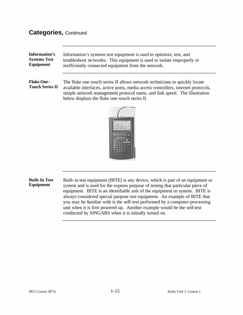
The fluke one-touch series II allows network technicians to quickly locate available interfaces, active ports, media access controllers, internet protocols, simple network management protocol name, and link speed. The illustration below displays the fluke one-touch series II.
Built-In Test Equipment
Built- in test equipment (BITE) is any device, which is part of an equipment or system and is used for the express purpose of testing that particular piece of equipment. BITE is an identifiable unit of the equipment or system. BITE is always considered special purpose test equipment. An example of BITE that you may be familiar with is the self- test performed by a computer-processing unit when it is first powered up. Another example would be the self-test conducted by SINGARS when it is initially turned on.

MCI Course 287A 1-16 Study Unit 1, Lesson Exercise
Lesson 1 Exercise
Directions Complete exercise items 1 through 4 by performing the action required.
Check your answers against those listed at the end of the lesson.
Item 1 What are the two types of test measurement and diagnostic equipment?
a. Electrical test equipment/Electronic test equipment b. Calibration test equipment/Mechanical test equipment c. Special purpose test equipment/General purpose test equipment d. Automatic test equipment/Built in test equipment
Item 2 An operator has turned in two different non-operational components for
repair. The technician used a type of TMDE that is designed to test a wide range of applications in both components. What type of TMDE was used? a. Multimeter b. Special purpose test equipment c. Ammeter d. General purpose test equipment
Item 3 Equipment used for test, repair, and maintenance of a specific system,
subsystem, or module having limited application is a definition of what type of TMDE? a. Special purpose test equipment b. Mechanical test equipment c. Limited technical equipment d. General purpose test equipment
Item 4 A HMMWV is inducted into the maintenance cycle and the mechanic decides
to check the hydraulic pressure in the braking system. What category of TMDE would be needed? a. Calibration TMDE b. Automatic test equipment c. Information’s system test equipment d. Mechanical test equipment
Continued on next page

MCI Course 287A 1-17 Study Unit 1, Lesson Exercise
Lesson 1 Exercise, Continued
Answers The table below provides the answers to the exercise items. If you have any
questions, refer to the reference page listed for each item.
Item Number Answer Reference 1 c 1-5 2 d 1-5 3 a 1-5 4 d 1-13

MCI Course 287A 1-18 Study Unit 1, Lesson Exercise
(This page intentionally left blank.)

MCI Course 287A 1-19 Study Unit 1, Lesson 2
LESSON 2
SAFETY
Introduction
Scope Safety in today’s Marine Corps is essential. In electronics, safety awareness
is essential for the well being of every technician. Failure to follow safety guidelines can endanger the lives of maintenance support personnel. During this lesson, we will discuss the indications of an electrical shock occurrence. This lesson will also present the factors affecting the severity of electric shock, steps to avoid it, as well as the treatment for a victim of electric shock.
Learning Objectives
After completing this lesson, you should be able to • Determine the cause of electric shock. • Identify the factors that affect the severity of electric shock. • Identify the steps that help to avoid electric shock. • Identify the treatment for electric shock.
In This Lesson This lesson contains the following topics:
Topic See Page Introduction 1-19 Electric Shock 1-20 Shock Avoidance 1-22 Rescue and Treatment 1-24 Lesson 2 Exercise 1-26

MCI Course 287A 1-20 Study Unit 1, Lesson 2
Electric Shock
Definition Electric shock is the sensation of muscular spasms caused by electrical
current passing through the body. When two parts of the body touch an energized electrical circuit, the effect is called electrical shock. It is the current, not the voltage that produces this sensation. No matter how much voltage is present, it is you providing a path for the current to follow that will shock you.
Factors The following are different factors that determine the severity of electric
shock: • Body resistance • Path • Time
Body Resistance
The amount of resistance the body has to the current flow will determine the amount of current. Less body resistance produces more current flow. Body resistance is dependent upon the parts of the body the current is passing through, whether or not the skin is wet.
Path The path that the current takes through the body will have entry and exit
points. These points will influence the severity of the shock received.
Time The length of time the current flows through the body also determines the
severity of the shock.
Continued on next page

MCI Course 287A 1-21 Study Unit 1, Lesson 2
Electric Shock, Continued
Effects The following table outlines the effects of electric shock:
Current (milliamperes)
Human Reaction (at 60 Hertz)
1.1 Perception: A slight tingling sensation.
10.0 16.0
Cannot let go: Arm and hand muscles close involuntarily: A 120-pound person A 175-pound person
18.0 Cannot breathe: Paralysis of the chest muscles. 65.0 Heart fibrillation: Rapid, irregular contractions of the
heart muscles. Could be fatal.

MCI Course 287A 1-22 Study Unit 1, Lesson 2
Shock Avoidance
Steps The following simple guidelines can help prevent electric shock:
• Isolate • Insulate • Ground
Isolate Isolate yourself from the source of electrical shock. Remove the power to the
equipment before attempting to work on it. Be sure to keep all electrical equipment covers, doors, and enclosures in place when not working on the equipment. If you must leave circuitry exposed, warn your fellow workers of the danger.
Insulate Make sure that the electrical tools, and equipment used are properly insulated.
Use only approved insulated hand and portable electric power tools. Check power and extension cords frequently fo r deterioration, cracks, or breaks. Breaks in the insulation can cause many electrical mishaps.
Ground Electric current always follows the path of least resistance. To prevent
yourself from being the unintentional path to ground, make sure that your equipment is well grounded. Well-grounded equipment will direct any stray electric current to ground, thereby protecting you from electric shock. A good ground can also help protect the equipment from excessive voltage spikes or lightning.
Continued on next page
MCI Course 287A 1-23 Study Unit 1, Lesson 2
Shock Avoidance, Continued
Additional Precautions
The following precautions will also help to avoid electric shock: • Always use test probes with safety guards or barriers on the probe tips to
prevent your hand from inadvertently touching the probe tip. • Always use insulated alligator clips. • Always keep your body clear of any metal parts of the equipment on which
you are working. • Always try to keep one hand in your pocket or behind your back when you
are taking a measurement to avoid creating a ground path for electric current flow through your body from hand to hand.

MCI Course 287A 1-24 Study Unit 1, Lesson 2
Rescue and Treatment
Promptness If someone is being shocked, rescue of the victim requires prompt action.
The difference between life and death can be determined in the first few minutes of discovery.
Actions The following actions should be taken in the case of an electric shock:
• Shut off power • Perform an initial medical assessment
Shut Off Power Upon discovery, the power must be shut off immediately. If power cannot be
shut off immediately, try to free the victim from the live conductor by using a dry board, belt, clothing, or other non-conducting material. Do not make direct contact with any part of the victim’s body with any part of your body! If you do, you may become part of the same circuit and you could become an electric shock victim yourself!
Initial Assessment
After removing the victim from the power source, determine if he or she is breathing. It is very important that the victim receive correct medical treatment as soon as possible. The steps below will ensure the victim is treated correctly and in the most expeditious manner: • Perform lifesaving steps • Care for the victim
Continued on next page

MCI Course 287A 1-25 Study Unit 1, Lesson 2
Rescue and Treatment, Continued
Lifesaving Steps
The table below lists the lifesaving steps.
Step Action
1 • Check to see if victim is breathing. • Apply cardiopulmonary resuscitation if the victim is not
breathing (CPR). Note: The American Red Cross recommends certification in a
CPR training course annually and certification in a first aid course every three years.
2 • Check again to see if victim is breathing. • Protect victim from exposure to cold with a warm cover if
victim is breathing. 4 Send for a doctor or a corpsman. 5 Stay with the victim until medical help has arrived.
Care The following items are important for a first responder to be aware of when
treating an electrical shock victim: • Associated traumas • Burns
Associated Trauma
Electrical injury is frequently associated with explosions or falls that can cause additional traumatic injuries, including both obvious external injuries and concealed internal injuries. Avoid moving the victim’s head or neck if a spinal injury is suspected. Administer appropriate first aid as needed for other wounds or fractures.
Burns If the victim has a burn, remove any clothing that comes off easily, and rinse
the burned area in cool running water until the pain subsides. Give first aid for burns.
Continued on next page
MCI Course 287A 1-26 Study Unit 1, Lesson 2 Exercise
Lesson 2 Exercise
Directions Complete exercise items 1 through 4 by performing the action required.
Check your answers against those listed at the end of the lesson.
Item 1 What causes the sensation that is considered electric shock?
a. Voltage b. Current c. Static electricity d. Resistance
Item 2 What factors affect the severity of electric shock?
1. ______________________________________ 2. ______________________________________ 3. ______________________________________
Item 3 Which of the following guidelines includes preventing yourself from being
the unintentional path for the electric current? a. Ground b. Isolate c. Insulate d. Probe
Item 4 What is the first action that should be taken when coming upon an electric
shock victim? a. Perform CPR. b. Shut off power. c. Remove from power source. d. Treat for shock.
Continued on next page

MCI Course 287A 1-27 Study Unit 1, Lesson 2 Exercise
Lesson 2 Exercise, Continued
Answers The table below provides the answers to the exercise items. If you have any
questions, refer to the reference page listed for each item.
Item Answer Reference 1 b 1-20 2 • Body resistance
• Path • Time
1-20
3 a 1-22 4 b 1-24

MCI Course 287A 1-28 Study Unit 1, Lesson 2 Exercise
(This page intentionally left blank.)

MCI Course 287A 1-29 Study Unit 1, Lesson 3
LESSON 3
ELECTROSTATIC DISCHARGE
Introduction
Scope Electrostatic discharge is counterproductive to the goal of repairing needed
equipment and returning it to those Marines who require it in the course of their duties. This lesson will cover what happens during an electrostatic discharge. It will also cover some conditions that produce electrostatic discharge, the rules, as well as the factors that can control it.
Learning Objectives
After completing this lesson, you should be able to • Identify conditions that would constitute an electrostatic discharge. • Identify conditions that produce an electrostatic discharge. • Identify the three rules for controlling electrostatic discharge. • Identify important factors in controlling electrostatic discharge.
In This Lesson This lesson contains the following topics:
Topic See Page Introduction 1-29 Effects 1-30 Conditions 1-31 Control Measures 1-32 Lesson 3 Exercise 1-35

MCI Course 287A 1-30 Study Unit 1, Lesson 3
Effects
Definition Electrostatic discharge (ESD) is the rapid transfer (discharge) of electrons or
electrical static charge from one object to another. ESD can damage or destroy electrical components. Note: ESD seems harmless, but it can damage most electronic components
and assemblies, which could result in deadlined equipment.
Warning Symbols
Since some devices are more susceptible to ESD than others, warning symbols like the ones shown below are used to identify ESD sensitive items.
Continued on next page

MCI Course 287A 1-31 Study Unit 1, Lesson 3
Conditions
Causes People often cause ESD. The body easily picks up static charges on your skin
and hair. The body can store relatively large amounts of static charges, which can be transferred or discharged. Listed below are some common causes and effects of ESD. • Friction: When an object comes into contact with another object, that
rubbing action causes static build up. • Separation: When an object is separated from another object. • Induction: Where a static charge is developed in an object, and that object
is brought close to another object which then becomes statically charged.
Static Producing Activity
Practically every movement a person makes creates static charges. Some of these actions are shown in the chart below.
Static Producing Activity Electrostatic Voltages Produced
Walking across carpet 1,500 to 35,000 V Walking on a vinyl floor 250 to 12,000 V Working at a bench 100 to 6,000 V Using poly bags 1,200 to 20,000 V

MCI Course 287A 1-32 Study Unit 1, Lesson 3
Control Measures
Rules There are three important rules that are used to control ESD:
• Assume that all components and assemblies are sensitive to ESD. • Handle ESD sensitive items only when properly grounded at a static safe
work area. The body is a prime source of ESD unless it is properly grounded.
• Store and transport ESD sensitive items in static shielding containers.
Important Factors
Along with the three rules, there are several factors to consider that helps control ESD, they are listed below: • Grounding: Grounding works on conductors. When equipment is properly
grounded, all conductors connect to a common point so that electrostatic charges will flow through the conductors and end up at the same point. Obviously, when working on electronic equipment, it is important that one of the conductors that must be grounded is the human body.
• Shielding: Shielding is used to prevent a sensitive device from being
charged by exposure to an external electrostatic field, or by being touched by a charged object during transport or storage. Always use metallized static shielding bags to protect static sensitive electronic components and assemblies.
• Ionization: Nonconductors must be neutralized by some means other than
grounding since they do not conduct electricity. The most common method of neutralizing insulators is through ionization. Ionizers flood an area with equal amounts of positive and negative charged particles (ions). A charged material will then attract ions of the opposite polarity and quickly become neutralized.
Continued on next page

MCI Course 287A 1-33 Study Unit 1, Lesson 3
Control Measures, Continued
ESD Free Work Environment
Without proper precautions, the work environment of maintenance support personnel could contribute to ESD. Listed below are some important ways to maintain an ESD free workplace. Keep in mind with regards to the work environment. • Keep the work area clean. • Dust all areas to avoid dirt-creating conditions that cause ESD. • Always wear ESD personal equipment. • Follow proper procedures for handling, storing, and transporting ESD
sensitive items.
Continued on next page

MCI Course 287A 1-34 Study Unit 1, Lesson 3
Control Measures, Continued
ESD Sensitive Device Precautions
The following are important ESD precautions: • Always ground the workbenches when handling ESDS devices. • Be sure that the technician is properly grounded. • Check packaging and equipment technical manuals for ESD warnings and
instructions. • Always ground the electrostatic unit package of an ESDS device or
assembly before opening it. • Always minimize the handling of ESDS devices or assemblies. • Always avoid unnecessary physical movement. • Always hold the ESDS device or assembly through its electrostatic- free
wrap, if possible, when removing or replacing it in the equipment. • Always touch, with the bare skin, the surface on which an ESDS device or
assemble rests for at least one second before you pick it up. • Always avoid repairs that require soldering at the equipment level, if
possible. • Always ground the leads of test equipment before energizing it and before
probing ESDS items. • Never permit ESDS devices or assemblies to come in contact with
ungrounded materials. • Whenever servicing ESDS devices, never touch or handle materials that
create static charges without repeating the grounding action.

MCI Course 287A 1-35 Study Unit 1, Lesson 3 Exercise
Lesson 3 Exercise
Directions Complete exercises 1 through 4 by performing the action required. Check
your answers against those listed at the end of the lesson.
Item 1 Which of the following scenarios would be considered electrostatic
discharge? a. A technician plugs in test equipment to a power source and experiences a
shock. b. A communications operator connects a piece of equipment to an incorrect
power source and immediately loses all power. c. A maintenance technician, while working on a radio, drops it in the water
and it short circuits. d. After walking on the carpet, a Marine brushes past his sergeant and feels a
slight shock.
Item 2 Which of the following is a cause of electrostatic discharge?
a. Friction b. Grounding c. Ionization d. Shielding
Item 3 Which one of the following is one of the three rules for controlling
electrostatic discharge? a. Always ground the workbenches when handling ESDS devices. b. Wear plastic gloves when handling ESDS devices. c. Dust all areas to avoid dirt-creating conditions that cause ESD. d. Store and transport ESD sensitive items in static shielding containers.
Continued on next page

MCI Course 287A 1-36 Study Unit 1, Lesson 3 Exercise
Lesson 3 Exercise, Continued
Item 4 One ESD control factor is to always use metallized static ___________ bags
to protect static sensitive electronic components and assemblies. a. grounding b. ionization c. shielding d. storing

MCI Course 287A 1-37 Study Unit 1, Lesson 3 Exercise
Lesson 3 Exercise, Continued
Answers The table below provides the answers to the exercise items. If you have any
questions, refer to the reference page listed for each item.
Item Number Answer Reference 1 d 1-30 2 a 1-31 3 d 1-32 4 c 1-32

MCI Course 287A 1-38 Study Unit 1, Lesson 3 Exercise
(This page intentionally left blank.)

MCI Course 287A 1-39 Study Unit 1, Lesson 4
LESSON 4
MODERN TMDE
Introduction
Scope Having a familiarity with the evolution of how test equipment has evolved
along with how it is presently used aids maintenance support personnel in proper utilization of equipment. Understanding measurement attributes aids maintenance personnel in selecting the correct test equipment for repair when presented with a potential problem. This lesson will cover early units of measurement, advantages and disadvantages of display methods, uses and advantages of embedded software, and identification of measurement attributes.
Learning Objectives
After completing this lesson, you should be able to • Identify early units of measurement. • Identify the advantage of digital display. • Identify the disadvantage of a digital display. • Identify an advantage of embedded software. • Identify the measurement attributes. • Identify how test equipment may have affected measurement readings.
Continued on next page

MCI Course 287A 1-40 Study Unit 1, Lesson 4
Introduction, Continued
In This Lesson This lesson contains the following topics:
Topic See Page Introduction 1-39 Evolution of Modern Measurement 1-41 Display Methods 1-42 Embedded Software 1-44 Measurement Attributes 1-45 Lesson 4 Exercise 1-47

MCI Course 287A 1-41 Study Unit 1, Lesson 4
Evolution of Modern Measurement
How the Ancients Measured
Going back in time to Noah’s ark, the lack of a yardstick was not a serious drawback. The accuracy of the measuring sticks were irrelevant when the craftsmen completed their projects one job at a time, rather than by assembling a number of different articles at one time for assembly at a later time. Generally, it did not matter how long a mile, yard, or an inch was or how heavy a pound or an ounce was. What was really important is that everyone meant the same thing when referring to each unit of measurement.
Metric System During Napoleon’s reign (in 1793), the French government adopted a new
system of standards called the metric system, which was based on the metre. The metre was supposed to be one tenth-millionth part of the distance from the North Pole to the Equator when measured on a straight line running along the surface of the earth through Paris. By 1837, France established the metric system on a permanent basis. Today, almost all countries of the world use a modernized version of the metric system.
Why Modern Measurement
Studying the history and development of measurements help provide a foundation for the evolution of modern TMDE. Humankind has come from the Vega unit of measure that was used in antiquity, to the modern measuring and testing of complex electrical equipment that is in use today. As technology advances, the need for more complex and exact standards of measurement were required, as well as the equipment to provide those measurements. Since humankind began to measure its surroundings, the one thing that is of utmost importance is having an acceptable standard of test and measurement.
Continued on next page

MCI Course 287A 1-42 Study Unit 1, Lesson 4
Display Methods
Display Methods
There are two methods for displaying the readings obtained by TMDE. Maintenance support personnel currently use both methods. Those two display methods are: • Analog • Digital
Analog Display Test equipment with analog displays present the results of a measurement
with a pointer deflection or by other visual means demonstrating quantity. A deflection is simply the departure of an indicator or pointer from a zero reading on the scale of an instrument to some other reading, demonstrating the scale of the pointer. The mechanism reacts to the applied stimulus. That reaction is displayed as the pointer moves across the face of the display and stops at some point where the magnitude of the reading can be taken.
Advantages There are no distinct advantages for using an analog TMDE.
Disadvantages Although analog displays have existed long before digital there are many
disadvantages to continued reliance on this kind of display. Analog meters are ruggedly constructed; however, the meter movement themselves are fragile and susceptible to damage if proper care is not taken. Analog meters are not as accurate as digital meters due to their construction and the method for output display. Note: Parallax error is a primary disadvantage. Parallax error is defined as
the error in reading an instrument, when the display scale, pointer, and observer’s eye are not in a line perpendicular to the plane of the scale.
Continued on next page

MCI Course 287A 1-43 Study Unit 1, Lesson 4
Display Methods, Continued
Digital Display When a measurement is shown digitally, it is in an alphanumeric format much
like a digital watch, or digital speedometer. A good way to gauge the relationship of analog and digital displays is to perform this simple test. Approach someone who owns a wristwatch with the face and hands (analog). Ask for the time. Usually the type of response you receive will be “around 9:30” or “about quarter after 6.” However, if you ask another person who has a watch with a digital display, you will be given the exact time! The owner of the digital display watch will respond, “9:28” instead of “around 9:30” or “6:17” instead of “about quarter after six.” You can see that through no more effort than it took to read the time on the watch, the accuracy of the reading or “measurement” has increased dramatically.
Advantages The advantages of digital display are two-fold one being increased accuracy;
the other is that the cost of digital TMDE, compared to analog, is much cheaper.
Disadvantages The only real issue with digital TMDE is essentially user acceptance. This
resistance on the part of the technician is found most often when an adjustment is made in a circuit, which causes increases and decreases in the voltage or current. Many technicians find it easier to watch the fluctuations in an analog scale and pointer, than a constantly changing digital readout. To some degree, manufacturers have addressed this by including a small analog scale and pointer next to the digital readout for use when making circuit adjustments. As time goes by, a younger generation technician who has grown up in the digital computer age is replacing the “old-salts.” These technicians are accustomed to digital displays.

MCI Course 287A 1-44 Study Unit 1, Lesson 4
Embedded Software
Uses Products that contain embedded software includes data network switching
equipment, automobile on-board diagnostic and service systems, modems, and sophisticated test equipment. Embedded software usually executes on an internal micro-controller or a digital signal processor (DSP), which is used to control other product components. Typically, such software must be extremely reliable, very efficient, compact, and precise in its handling of the rapid and unpredictable timing of inputs and outputs.
Advantages This software is useful because it can identify potential faults much quicker
than conventional test equipment. Often, faults can be identified during equipment startup procedures, saving countless maintenance hours, and reducing downtime. Another advantage of embedded software is that it can often eliminate the need for external test equipment.

MCI Course 287A 1-45 Study Unit 1, Lesson 4
Measurement Attributes
Examples The following are examples of measurement attributes:
• Sensitivity • Resolution • Dynamic Range • Linearity • Accuracy • Sample rate • Circuit loading
Sensitivity Sensitivity for an electronic device is defined as the minimum input signal
required to produce a specified output signal possessing a particular signal-to-noise ratio or some other specified criteria. In essence, sensitivity is the measure of an instrument’s ability to respond to minimum level signals with the instrument’s rated degree of accuracy. It is important to know the instrument’s sensitivity, so it is not exceeded when making a measurement.
Resolution Resolution specifies the smallest change in a physical property that causes a
change in the measurement or sourced quantity. Resolution is also referred to as resolving power when dealing with optical systems. It is the ability of a lens or optical system to form separate and distinct images of two objects with small angular separation. The resolving power of an optical system is ultimately limited by the wavelength involved and the diffraction by the aperture, where a larger aperture has a greater resolving power than a smaller one.
Dynamic Range Dynamic range is the difference between the maximum level of a parameter
such as power, current, voltage or frequency, and the smallest level of that same parameter that a piece of test equipment can measure at the same time. This is different from measurement range, which is the difference between the largest and smallest signal that can be measured, but not simultaneously. Dynamic range is usually expressed in dB.
Continued on next page

MCI Course 287A 1-46 Study Unit 1, Lesson 4
Measurement Attributes, Continued
Linearity Linearity is the difference in the accuracy values through the expected
operating range of the equipment. It can also be expressed as how the output changes with respect to the input. The output of a perfectly linear device will always increase in direct proportion to an increase in its input.
Accuracy Accuracy is defined as the ability of a measurement to match the actual value
of the quantity being measured. The accuracy of test equipment is the degree of conformity of the results with respect to a standard reference. For example, if a known value, say a 50 MHz signal is inputted into the equipment; it is reasonable to expect that the test equipment will measure the signal at 50 MHz. Accuracy can also be described as the maximum error in the measurement of a physical quantity in terms of the output of an instrument, when referred to the individual instrument’s calibration. Accuracy is usually given as a percentage of full scale. Accuracy is important because if the measurements are not accurate, whatever decision the technician makes based on those measurements will be flawed.
Sample Rate Sample rate is defined as the number of times a signal is measured (sampled)
in a unit of time. The more time between samples, the less accurate the reading. Thus a higher sample rate typically results in more accurate measurements.
Circuit Loading Circuit loading caused by test equipment is defined as the power drawn from
a circuit by an electrical measuring instrument, which may alter significantly the quantity being measured. For example, if an inexpensive voltmeter is used to test a circuit, the internal resistance of the voltmeter may add to the total resistance of the circuit and cause an inaccurate reading.

MCI Course 287A 1-47 Study Unit 1, Lesson 4 Exercise
Lesson 4 Exercise
Directions Complete exercise items 1 through 6 by performing the action required.
Check your answers against those listed at the end of the lesson.
Item 1 In early measurements, what was really important is that everyone meant
the _________ _________ when referring to each unit of measurement.
Item 2 Which of the following is an advantage of digital display?
a. Has a display that catches the eye. b. Is much more accurate than analog display. c. Can give a better display of time. d. Has been around longer than analog display.
Item 3 Which of the following is a disadvantage of digital display?
a. Difficulty in reading b. Hard to read c. Parallax d. User acceptance
Item 4 Which of the following is an advantage of embedded software?
a. Controls other product components. b. Executes on digital signal processor. c. Saves maintenance man-hours. d. Provides training for maintenance support personnel.
Continued on next page

MCI Course 287A 1-48 Study Unit 1, Lesson 4 Exercise
Lesson 4 Exercise, Continued
Item 5 What are four measurement attributes?
1. __________________________________________________
2. __________________________________________________
3. __________________________________________________
4. __________________________________________________
Item 6 Lance Corporal Smith used an inexpensive voltmeter to test a
communications circuit. The reading of the voltmeter was extremely different than what was expected from that particular circuit. What could have caused the difference? _____________________________________________________________
Continued on next page

MCI Course 287A 1-49 Study Unit 1, Lesson 4 Exercise
Lesson 4 Exercise, Continued
Answers The table below provides the answers to the exercise items. If you have any
questions, refer to the reference page listed for each item.
Item Number Answer Reference 1 same thing 1-41 2 b 1-43 3 d 1-43 4 c 1-44 5 Any four of the following are
correct: • Sensitivity • Resolution • Dynamic range • Linearity • Accuracy • Sample rate • Circuit loading
1-45
6 Circuit loading 1-46

MCI Course 287A 1-50 Study Unit 1, Lesson 4 Exercise
(This page intentionally left blank.)

MCI Course 287A 2-1 Study Unit 2
STUDY UNIT 2
CATEGORIES OF TEST MEASUREMENT INSTRUMENTS
Overview
Scope Occupations such as carpenters, plumbers, and bricklayers are familiar with
the need to “use the right tool for the job.” Maintenance support personnel must abide by this rule as well, because they often use many of the same tools as the occupations just mentioned. This rule is just as true in selecting test measurement and diagnostic equipment (TMDE), which represents an exclusive set of tools used by maintenance support personnel that is often misunderstood. Before going to the TMDE “toolbox,” you must know the name, purpose, and proper use of that tool to prevent using the wrong tool for the job. The following information will examine closely the categories, uses of, and the varying degrees of test measurement instruments.
In This Study Unit
This study unit contains the following lessons:
Lesson See Page
Power-Measuring Instruments 2-3 Waveform Generating Instruments 2-13 Time Domain Instruments 2-21 Frequency Domain Instruments 2-29 Digital Domain Instruments 2-39

MCI Course 287A 2-2 Study Unit 2
(This page intentionally left blank.)

MCI Course 287A 2-3 Study Unit 2, Lesson 1
LESSON 1
POWER-MEASURING INSTRUMENTS
Introduction
Scope This lesson presents power-measuring instruments. This lesson will also look
at some general examples and some uses of the instruments.
Learning Objectives
After completing this lesson, you should be able to • Identify four power-measuring instruments. • Identify the use of a power meter. • Identify what a multimeter is used for. • Identify types of ground testers.
In This Lesson This lesson contains the following topics:
Topic See Page Introduction 2-3 Power Meters 2-4 Wattmeters 2-6 Multimeters 2-7 Ground Tester 2-8 Lesson 1 Exercise 2-10

MCI Course 287A 2-4 Study Unit 2, Lesson 1
Power Meters
Use A power meter may be used to measure the electrical power that a source is
capable of delivering a specified load, or the electrical power that a source furnishes to an arbitrary load. Two types of power meters are listed below: • Peak power meters • Continuous wave (CW) power meters
Peak Power Meters
Peak power meters are specialized power meters designed to measure pulse-modulated signals. In order to present the measured results as a function of time, these power meters often include a display similar to an oscilloscope. An example of a peak power meter is called the peak power meter (TAMCN A7053).
Peak Power Meter (TAMCN A7053)
The peak power meter is intended to support microwave systems that use pulse modulation such as radars, and that operate of frequencies above 1 GHZ.
Continuous Wave Power Meters
Continuous wave (CW) power meters function under the same general principles as peak power meters in that they support systems that operate at frequencies above 1 GHz. Rather than measuring pulse-modulated signals, CW power meters measure continuous wave signals. An example of a continuous wave power meter is called the power meter (TAMCN A7051).
Continued on next page

MCI Course 287A 2-5 Study Unit 2, Lesson 1
Power Meters, continued
Powe r Meter (TAMCN A7051)
This power meter is intended to support microwave systems that operate at frequencies above 1 GHz that uses CW signals. The illustration below displays the power meter.

MCI Course 287A 2-6 Study Unit 2, Lesson 1
Wattmeters
Uses A wattmeter provides a reading of power a circuit is providing for
transmission. Power measurements represent the amount of power being consumed by the wattmeter and are a derivative of voltage and current being applied to the wattmeter. The two basic application types are the insertion, or in- line meter, and the terminating or load meter. The measured voltage and measured current provide an indication of power consumed, with the displayed being the watt. An example of a wattmeter is called the radio frequency monitor unit (TAMCN A7055).
Radio Frequency Monitor Unit (TAMCN A7055)
This frequency monitor is an insertion type radio frequency (RF) wattmeter designed to measure power flow and load match in 50 RF coaxial transmission lines, and is intended for use on CW or FM signals only. The test set consists of a wattmeter, termaline load resistor, two cable assemblies, four elements, adapter, variable sampler, VSWR chart, and spare battery. Optional plug- in elements are available for higher frequencies. The illustration below displays the radio frequency monitor unit.

MCI Course 287A 2-7 Study Unit 2, Lesson 1
Multimeters
Functions The most popular type of meter available in both analog and digital form is
the multimeter. A multimeter is usually a voltmeter, ammeter, and ohmmeter combined into one instrument. Typically, either an ammeter or voltmeter is implemented internally, which is then used to perform the other functions. Many multimeters measure amps, ohms and volts. Some advanced multimeters include integrated oscilloscope functions. Two types are listed below: • Handheld digital multimeter (TAMCN H7017) • Handheld multimeter (TAMCN H7025)
Handheld Digital Multi-meter (TAMCN H7017)
This multimeter allows measurements of ac/dc volts, ac/dc amps, ohms, diode tests, continuity, and peak-hold. This multimeter has a high degree of accuracy. The illustration below displays the handheld digital multimeter.
Handheld Multimeter (TAMCN 7025)
This handheld multimeter measures the same attributes as the TAMCN H7017; however, it is intended for those applications where a ruggedized, waterproof meter is required. The illustration below displays this ruggedized handheld multimeter.

MCI Course 287A 2-8 Study Unit 2, Lesson 1
Ground Testers
Functions Ground testers are special instruments used to test the earth’s resistance to a
buried ground electrode. Many technicians are tempted to use an ohmmeter rather than find a ground tester, which can result in an inaccurate measurement. The problem with using an ohmmeter is that electrical measurements are normally performed on a circuit designed for a specific purpose. This is not the case with a ground measurement. With a ground tester, the electrode under test has been installed in the available soil, and that soil (not a specifically designed circuit) is the critical part of the measurement. There are different types of ground testers. Two types are listed below: • Four-point tester • Clamp-on tester
Four-Point Tester
The four-point tester method for ground testing is the basic method described previously, and involves inserting four rods into the earth at specific intervals. The ground must be disconnected from the power system before the resistance can be tested. An example of a four-point method tester is called the ground tester (TAMCN A7059).
Ohmmeter, Ground Tester (TAMCN A7059)
This equipment is an earth ground tester that uses the null-balance method. The illustration below displays the ohmmeter ground tester.
Note: Null or balance methods involve using instrumentation to measure the
difference between two similar quantities, one of which is known as very accurate and is adjustable.
Continued on next page

MCI Course 287A 2-9 Study Unit 2, Lesson 1
Ground Testers, Continued
Clamp-on Ground Testers
Clamp-on ground testers have an advantage over other ground testers in that ground resistance can be measured without disconnecting the ground from the power system. In addition, a clamp-on tester saves time when performing tests because only one operator is needed. Lastly, the clamp on tester is easy to operate. The technician clamps the tester onto the ground rod or conductor leading to the ground rod and pushes a button. Within seconds, the measurement is displayed. An example of a clamp-on tester is called the ohmmeter, ground tester (TAMCN A7057).
Ohmmeter, Ground Tester (TAMCN A7057)
This ground tester is a clamp-on ground tester. It measures resistance and current flow of earth ground rods. This equipment must be used on multi-ground systems. The illustration below displays the clamp-on ground tester.

MCI Course 287A 2-10 Study Unit 2, Lesson 1 Exercise
Lesson 1 Exercise
Directions Complete exercise items 1 through 4 by performing the action required.
Check your answers against those listed at the end of the lesson.
Item 1 What are two types of power-measuring instruments?
1. ________________________________________
2. ________________________________________
Item 2 A power meter may be used to measure the ___________ ___________that
a source is capable of delivering to specified load impedance, or it can be used to measure the electrical power that a source furnishes to an arbitrary ____________.
Item 3 Name three measurements the multimeter is used to measure.
1. _____________________________________________________ 2. _____________________________________________________ 3. _____________________________________________________
Item 4 What are two types of ground testers?
1. ______________________________________________________ 2. ______________________________________________________
Continued on next page

MCI Course 287A 2-11 Study Unit 2, Lesson 1 Exercise
Lesson 1 Exercise, Continued
Answers The table below provides the answers to the exercise items. If you have any
questions, refer to the reference page listed for each item.
Item Number Answer Reference 1 Any two of the
following are correct: • Power meter • Wattmeter • Multimeter • Ground tester
2-4 through 2-8
2 • electrical power, load 2-4 3 • amps
• ohms • volts
2-7
4 • four-point • clamp-on
2-8

MCI Course 287A 2-12 Study Unit 2, Lesson 1 Exercise
(This page intentionally left blank.)

MCI Course 287A 2-13 Study Unit 2, Lesson 2
LESSON 2
WAVEFORM GENERATING INSTRUMENTS
Introduction
Scope This lesson covers waveform generating instruments. This lesson will also
present some general examples and some uses of these instruments.
Learning Objectives
After completing this lesson, you should be able to • Identify the definition of a waveform instrument. • Identify the types of function generators. • Identify the types of microwave signal generators.
In This Lesson This lesson contains the following topics:
Topic See Page Introduction 2-13 Waveform Generators 2-14 Function Generators 2-15 Radio Frequency Generators 2-17 Microwave Generators 2-18 Lesson 2 Exercise 2-19

MCI Course 287A 2-14 Study Unit 2, Lesson 2
Waveform Generators
Definition Waveform generating instruments are used to produce various signal sources
for a broad spectrum of equipment in a laboratory environment. These signals are then injected into equipment under test, in order to diagnose or confirm it is functioning properly. Three examples of waveform generators are listed below: • Function generators • Radio frequency (RF) generators • Microwave generators

MCI Course 287A 2-15 Study Unit 2, Lesson 2
Function Generators
Definition Function generators are a class of oscillator based signal sources in which the
technician can choose an output waveform. Function generators also provide continuous tuning over wide bands with max/min frequency ratios of 10 or more sub-Hz to MHz frequencies, flat output amplitude, and sometimes modulation capabilities, frequency sweeping, frequency modulation (FM), and amplitude modulation (AM). There are various types of function generators. Three are listed below: • Arbitrary waveform • Pulse waveform • Serial data
Arbitrary Waveform
An arbitrary waveform generator simplifies the sample sine-wave synthesis technique to allow other waveforms to be stored in memory. Using an arbitrary waveform generator, the technician can determine the shape of one period of the waveform and its repetition rate. This is a very useful ability for many applications. An example of an arbitrary waveform generator is called the function generator (TAMCN A7038). Note: Sine-wave is a unique waveform that represents energy entirely
concentrated at a single frequency. The current or voltage varies with the sine of the elapsed time.
Function Generator (TAMCN A7038)
This function generator is also a fully programmable pulse generator. Features include sine, triangle, ramp, square, pulse, haversine, havertriangle, and direct current (DC) output waveforms. Additional features include DC offset, burst and logarithmic sweep, frequency, amplitude, and pulse width modulation trigger output.
Pulse Waveform Generators
The pulse waveform generators are designed to produce high-quality square waves and pulse trains. Pulse waveform generators are typically used in digital systems to simulate or replace digital signals such as clocks and data control lines. Pulse waveform generators can also be used in analog systems. An example of a pulse waveform generator is called the pulse generator (TAMCN H7004).
Continued on next page

MCI Course 287A 2-16 Study Unit 2, Lesson 2
Function Generators, Continued
Pulse Generator (TAMCN H7004)
This pulse generator is portable and is also general-purpose test equipment used for modulating signal sources. Features include positive and negative pulse output, single and double pulse capability, and pulse synch from external signal, gated operation, adjustable delay, and variable pulse width. The illustration below displays the pulse generator.
Serial Data Generator
Serial data generators are used primarily for testing modems, the serial port of a computer, and some satellite systems. Serial data is data that is delivered one bit at a time. An example of a serial data generator is called the function generator (TAMCN A7036).
Function Generator (TAMCN A7036)
This function generator is general-purpose test equipment intended to support a wide variety of equipment and functions. Features include sine, triangle and square waveforms. This is considered a low-end function generator. If more capabilities or faster speeds are required, use TAMCN A7038. The illustration below displays the function generator.

MCI Course 287A 2-17 Study Unit 2, Lesson 2
Radio Frequency Generators
Radio Frequency Generators
Radio frequency (RF) generators are a class of waveform generating instruments, which produce radio receiver test signals with accurate frequencies and amplitudes over wide ranges. RF generators can be used to support any piece of equipment, which operates in the RF range, such as radar controllers. An example of an RF generator is called the signal generator (TAMCN A7052).
Signal Generator (TAMCN A7052)
This signal generator is general-purpose generator, and is intended to support a wide variety of equipment and functions. It is intended to support maintenance of equipment and systems that operate below 1 GHz. The graphic below illustrates the signal generator.

MCI Course 287A 2-18 Study Unit 2, Lesson 2
Microwave Generators
Types Generators used to test modern communications, satellite, radar, navigational,
electronic warfare (EW), and surveillance receivers require the ability to produce very precise signals across a dynamic range of frequency and magnitude. Microwave generators produce clean, calibrated electrical signals for the testing and characterization of sophisticated microwave receivers. There are several types of microwave signal generators. Some examples are listed below: • Continuous wave (CW) signal generators • Swept signal generators • Signal generators with modulation • Signal generators with frequency agility and high-performance modulation
Continuous Wave Signal Generators
CW signal generators can be used as exciters in transmitter testing, or as sources driving amplifiers or modulators.
Swept Signal Generators
Swept signal generators can be used for the test and characterization of components and subsystems and for general-purpose applications. They can be used with scalar and vector network analyzers, or with power meters and detectors. Swept signal generators can also be used for antenna tests.
Signal Generators with Modulation
Signal generators with modulation are designed to test very sophisticated receivers where the generation of accurately calibrated signals at various levels over a wide dynamic range is required.
Signal Generators with Frequency Agility and High- Performance Modulation
Signal generators with frequency agility and high-performance modulation are used when simulations of complex scenarios involving multiple targets or emitters need to be carried to test radar or EW receivers. They can also be used to perform certain tests on satellite or communications receivers.

MCI Course 287A 2-19 Study Unit 2, Lesson Exercise
Lesson 2 Exercise
Directions Complete exercises items 1 through 3 by performing the action required.
Check your answers against those listed at the end of the lesson.
Item 1 Waveform generating instruments are used to produce various ___________
sources in a laboratory environment.
a. signal b. equipment c. spectrum d. microwave
Item 2 Which one is a type of function generator?
a. Arbitrary waveform b. Signal generator c. Radio frequency counter d. General purpose
Item 3 What are three types of microwave signal generators?
1. ________________________________________ 2. ________________________________________ 3. ________________________________________
Continued on next page

MCI Course 287A 2-20 Study Unit 2, Lesson Exercise
Lesson 2 Exercise, Continued
Answers The table below provides the answers to the exercise items. If you have any
questions, refer to the reference page listed for each item.
Item Number Answer Reference 1 a 2-14 2 a 2-15 3 Any three of the
following are correct: • Continuous wave • Swept signal • Signal generators
with modulation • Signal generators
with frequency agility and high-performance modulation
2-18

MCI Course 287A 2-21 Study Unit 2, Lesson 3
LESSON 3
TIME DOMAIN INSTRUMENTS
Introduction
Scope This lesson covers time domain instruments. This lesson will provide some
general examples and some uses of these instruments.
Learning Objectives
After completing this lesson, you should be able to • Identify the purpose of a time domain instrument. • Identify the different kinds of time domain instruments. • Identify a type of an oscilloscope. • Identify the purpose of cable diagnostic devices.
In This Lesson This lesson contains the following topics:
Topic See Page Introduction 2-21 Usage 2-22 Oscilloscopes 2-23 Cable Diagnostic Devices 2-24 Lesson 3 Exercise 2-26

MCI Course 287A 2-22 Study Unit 2, Lesson 3
Usage
Different Kinds Time domain instruments are used to observe and evaluate how a signal
behaves over time. There are different kinds of time domain instruments. In this lesson, you will study those listed below: • Oscilloscopes • Cable diagnostic devices

MCI Course 287A 2-23 Study Unit 2, Lesson 3
Oscilloscopes
Types Oscilloscopes play an important role in testing a variety of equipment. Two
types of oscilloscopes are listed below: • Analog • Digital
Analog An analog oscilloscope works by applying voltage being measured to an
electron beam moving across the oscilloscope screen. The voltage deflects the beam up and down, producing a waveform that is proportional to the amplitude of the signal being measured at any given time. This gives an immediate picture of the waveform.
Digital Digital oscilloscopes sample the waveform, and use an analog-to-digital
converter (ADC) to convert the voltage being measured into digital information. It then uses this digital information to reconstruct the waveform on the screen.

MCI Course 287A 2-24 Study Unit 2, Lesson 3
Cable Diagnostic Devices
Purpose Cable diagnostic devices are designed to test and perform diagnostics on
cables used in telecommunications and computer networks. Two examples of TMDE cable diagnostic devices are listed below: • Time domain reflectometer (TDR) • 26 pair cable testers
Reflectometer TDR is used for all aspects of cable systems from installation through
maintenance. Due to the complexity of operation and expense, TDRs are used only in large companies and by high- level engineers. TDRs troubleshoot and measure many types of twisted pairs and coaxial cables. They can locate major or minor cabling problems. A technician can use a TDR to determine the type of problem and the exact physical location of the fault. The two types of TDRs in the TMDE inventory are listed below: • Metallic time domain reflectometer • Optical time domain reflectometer
Metallic Time Domain Reflectometer
A metallic TDR works on the same principle as radar. A TDR sends out a pulse along the cable. When the pulse reaches the end of the cable, or encounters a fault along the cable part, all of the pulse energy is reflected back to the instrument. Any impedance change in the cable will cause some energy to reflect back toward the TDR and be displayed.
Optical Time Domain Reflectometer
An optical time domain reflectometer (OTDR) is an instrument specially designed to test an optical fiber. The OTDR sends a series of optical pulses into the fiber and collects the light, which is reflected back along the fiber. The intensity of the returned pulses is measured and integrated as a function of time and plotted as a function of fiber length. From this data, the technician can determine whether the optical fiber is intact. An OTDR can also be used for estimating the length of the fiber and its overall attenuation. It can measure any losses resulting from splices or mated-connectors and is used to locate any faults.
Continued on next page

MCI Course 287A 2-25 Study Unit 2, Lesson 3
Cable Diagnostic Devices, Continued
26 Pair Cable Tester
Unlike a TDR, a 26 pair cable tester is not capable of isolating the fault in the cable. It is simply a pass/fail indicator.

MCI Course 287A 2-26 Study Unit 2, Lesson 3 Exercise
Lesson 3 Exercise
Directions Complete exercises 1 through 4 by performing the action required. Check
your answers against those listed at the end of the lesson.
Item 1 Time domain instruments are used to ________, and _________ how a signal
behaves over time.
Item 2 What is one kind of time domain instrument?
a. Analog b. Digital c. Oscilloscopes d. Analog digital converter
Item 3 Name a type of an oscilloscope.
1. _______________________________________
Item 4 Cable diagnostic devices are designed to ___________ and perform
_____________ on cables used in telecommunications and computer networks.
Continued on next page

MCI Course 287A 2-27 Study Unit 2, Lesson 3 Exercise
Lesson 3 Exercise, Continued
Answers The table below provides the answers to the exercise items. If you have any
questions, refer to the reference page listed for each item.
Item Number Answer Reference 1 observe, evaluate 2-22 2 c 2-22 3 • analog
• digital 2-23
4 test, diagnostics 2-24

MCI Course 287A 2-28 Study Unit 2, Lesson 3 Exercise
(This page intentionally left blank.)

MCI Course 287A 2-29 Study Unit 2, Lesson 4
LESSON 4
FREQUENCY DOMAIN INSTRUMENTS
Introduction
Scope This lesson covers frequency domain instruments. This lesson will also
provide some general examples and uses of these instruments.
Learning Objectives
After completing this lesson, you should be able to • Identify the categories of frequency domain instruments. • Identify the definition of a frequency domain instruments.
In This Lesson This lesson contains the following topics:
Topic See Page Introduction 2-29 Usage 2-30 Frequency Counters 2-31 Spectrum Analyzers 2-34 Network Analyzers 2-35 Lesson 4 Exercise 2-37

MCI Course 287A 2-30 Study Unit 2, Lesson 4
Usage
Definition Frequency domain instruments evaluate the frequency “spectrum” used by the
signal, and how the signal relates to other signals that also occupy the spectrum on nearby frequencies.
Categories Within the frequency domain inventory, the following categories exist:
• Frequency counters • Spectrum analyzers • Network analyzers

MCI Course 287A 2-31 Study Unit 2, Lesson 4
Frequency Counters
Introduction Frequency counters measure the frequency of a signal. They use stable
crystal oscillators and digital counting circuits to provide simple non-error prone frequency and period measurements. Frequency counters are commonly used for radio frequency measurements, but can be used for lower frequency measurements. Frequency counters are typically broken down by the type of wave they measure and fall into one of the following groups: • Pulse • Continuous wave (CW) • Radio frequency • Microwave
Pulse Frequency Counters
Pulse frequency counters are designed to measure pulse signals and support pulse signal equipment such as radars and some communication equipment. Some of them can also measure continuous wave signals. An example of a pulse frequency counter is called the microwave pulse counter (TAMCN A7035).
Microwave Pulse Counter (TAMCN A7035)
This unit is capable of pulse and CW frequency measurement, and features 9-digit frequency display, 10 MHz output, gate output, and IEEE-488 bus interface. The pulse counter is intended to support equipment and systems that use pulse signals. The illustration below displays the microwave pulse counter.
Continued on next page

MCI Course 287A 2-32 Study Unit 2, Lesson 4
Frequency Counters, Continued
Continuous Wave Frequency Counters
Continuous wave (CW) frequency counters are designed to measure CW signals (signals in the microwave bands). CW signals are non-pulsed signals. They are used to support all equipment and systems that operate above 1 GHz and emit continuous wave signals. An example of a continuous wave frequency counter is called the microwave frequency counter (TAMCN A7025).
Microwave Frequency Counter (TAMCN A7025)
This unit is intended to support all equipment and systems that operate above 1 GHz. This counter only measures CW signals. The illustration below displays the microwave frequency counter.
Continued on next page

MCI Course 287A 2-33 Study Unit 2, Lesson 4
Frequency Counters, Continued
Radio Frequency Counters
Radio frequency (RF) counters are designed for the purpose of measuring signals in the RF range and typically covers signals up to approximately 1 GHz. An example of a radio frequency counter is called the electronic frequency counter (TAMCN A7021).
Electronic Frequency Counter (TAMCN A7021)
This counter is used to measure frequency, period, period average, time interval, time interval average, and ration of RF signals up to 1.3 GHz. Features include marker output, 1 MHz output, and AC and DC coupling. The illustration below displays the electronic frequency counter.
Microwave Frequency Counters
Microwave frequency counters are designed for the purpose of measuring signals in the microwave range, which typically includes frequencies above 1 GHz. Other examples of these counters can be found under pulse and CW frequency counters.

MCI Course 287A 2-34 Study Unit 2, Lesson 4
Spectrum Analyzers
Purpose Spectrum analyzers are frequency domain devices that can examine signals as
a function of amplitude versus frequency. It can break down a signal so that the fundamental sine wave and all existing harmonics (additional sine waves) are visible. In addition, it will show the amplitude and frequency of each harmonic to enable further analysis. Spectrum analyzers are broken down into the following two categories: • High frequency • Low frequency
High Frequency
High frequency spectrum analyzers operate in frequencies in excess of 1 GHz. These analyzers are commonly used to test microwave and radar systems.
Low Frequency A low frequency spectrum analyzer typically operates within the 20 to 20,000
Hz frequency range. These analyzers are normally used to test audio amplifiers.

MCI Course 287A 2-35 Study Unit 2, Lesson 4
Network Analyzers
Purpose Network analyzers accurately measure the transfer function or impedance
characteristic of linear networks across a broad range of frequencies that generally starts at about 1 MHz. Marine Corps calibration labs use this equipment to test and troubleshoot GPTE. There are two types of network analyzers in the TMDE inventory: • Scalar • Vector
Scalar A scalar network analyzer is used for accurately measuring transmission and
reflection characteristics. An example of a scalar network analyzer is called the agilent model 8757D scalar network analyzer.
Agilent Model 8757D Scalar Network Analyzer
The agilent model 8757D scalar network analyzer allows a technician to measure insertion loss, gain, and return loss. Setup time is reduced because measurement data can be sent directly to a printer while you proceed to the next measurement. The illustration below displays the agilent model 8757D network analyzer.
Continued on next page

MCI Course 287A 2-36 Study Unit 2, Lesson 4
Network Analyzer, Continued
Vector A vector network analyzer is used to characterize RF and microwave
components. An example of a vector network analyzer is called the agilent model 8720ES vector network analyzer.
Agilent Model 8720ES Vector Network Analyzer
The agilent model 8720ES vector network analyzer allows complete characterization of RF and microwave components. The 8720ES includes an integrated synthesized source test set and tuned receiver. The built- in S-parameter test set provides a full range of magnitude and phase measurements in both directions; forward and reverse.

MCI Course 287A 2-37 Study Unit 2, Lesson 4 Exercise
Lesson 4 Exercise
Directions Complete exercises 1 through 2 by performing the action required. Check
your answers against those listed at the end of the lesson.
Item 1 What are three categories of frequency domain instruments?
1. _______________________________________________ 2. _______________________________________________ 3. _______________________________________________
Item 2 Frequency domain instruments evaluate the frequency ______________ used
by the signal.
Continued on next page

MCI Course 287A 2-38 Study Unit 2, Lesson 4 Exercise
Lesson 4 Exercise, Continued
Answers The table below provides the answers to the exercise items. If you have any
questions, refer to the reference page listed for each item.
Item Number Answer Reference 1 • Frequency counters
• Spectrum analyzers • Network analyzers
2-30
2 spectrum 2-30

MCI Course 287A 2-39 Study Unit 2, Lesson 5
LESSON 5
DIGITAL DOMAIN INSTRUMENTS
Introduction
Scope This lesson covers digital domain instruments. This lesson will also provide
some general examples and some uses of these instruments.
Learning Objectives
After completing this lesson, you should be able to • Identify the two main categories of digital domain instruments. • Given a scenario determine the network test set needed. • Identify digital information test equipment.
In This Lesson This lesson contains the following topics:
Topic See Page Introduction 2-39 Usage 2-40 LAN and WAN Test Sets 2-41 Computer Test Sets and Digital Information Test Equipment
2-42
Lesson 5 Exercise 2-44

MCI Course 287A 2-40 Study Unit 2, Lesson 5
Usage
Definition Digital domain instruments are used to check the proper function and timing
of networks, collect and display information in the format and language of digital circuit, and analyze data streams. The two main categories of digital domain instruments are listed below: • Local area network (LAN) and wide area network (WAN) test sets • Computer test sets and digital information test equipment

MCI Course 287A 2-41 Study Unit 2, Lesson 5
LAN and WAN Test Sets
Local Area Network
A local area network (LAN) test set is typically used for measurements during startup operation, acceptance testing and maintenance of Ethernet, and token ring networks. It can also be used for network optimization and troubleshooting. An organizational e-mail account or defense messaging account would represent a LAN where these types of test sets are useful. An example of an LAN test set is called the local area network test set (TAMCN A7084).
Example The TAMCN A7084 is an example of a LAN test set used to test and monitor
computer local area networks both garrison and tactical units.
Wide Area Network
A wide area network (WAN) test set or protocol analyzer is used to troubleshoot network problems and to monitor the performance of networks. An example of a WAN test set is called the OptiView by Fluke.
OptiView by Fluke
The OptiView combines a high-performance protocol analyzer and a cable tester into one hand-held device. The OptiView integrates active discovery in switched networks, seven- layer analysis, fully automatic internet protocol (IP) configuration even without dynamic host configuration protocol (DHCP), address-to-name mapping, SNMP device analysis, traffic generation, and cable testing.

MCI Course 287A 2-42 Study Unit 2, Lesson 5
Computer Test Set and Digital Information Test Equipment
Usage of Computer Test Sets
The computer test sets is made up of different pieces of stand-alone equipment. They are primarily used to test computer monitors and central processing units (CPU).
Usage of Digital Information Test Equipment
This equipment is used to debug software, trace program flow, and measure event timing. It is also used to support and maintain data communication equipment and systems. Two important types of digital information test equipment are listed below: • Bit error rate testers • Logical analyzers
Bit Error Rate Tester
A bit error rate tester (BERT) examines the 1s and 0s in a data stream against a known pattern and alerts the technician to discrepancies. Many BERTs also look for technology-specific errors and indicators such as frame loss, bipolar violations, network alarm detection, synchronization loss, and clock signal loss. An example of a bit error rate tester is called the fireberd (FB)-6000A data communications analyzer.
FB-6000A Data Analyzer
This analyzer uses the bit error rate method to test data communications. Test results are displayed as bit errors, bit error rate, seconds with errors, error- free seconds, availability, bipolar violations, and excess zero detection. The FB 6000 is intended to support all types of data communication equipment and systems. The illustration below displays the FB-6000 data analyzer.
Continued on next page

MCI Course 287A 2-43 Study Unit 2, Lesson 5
Computer Test Set and Digital Information Test Equipment, Continued
Logic Analyzers
Logic analyzers collect and display information in the format and language of digital circuits. Most logic analyzers can be configured to format their output as a sequence of assembly processor instructions, or as high- level language source code. This makes them very useful for debugging software. For real-time-crucial embedded controllers, a logic analyzer is an excellent tool for both tracing program flow and measuring event timing. An example of a logic analyzer is called the digital logic analyzer (TAMCN A7011).
Digital Logic Analyzer (TAMCN A7011)
This digital analyzer has comprehensive recordings and displays analysis capabilities that enable the technician to perform complex timing and storage analysis of digital signals. It has a built- in flow disk drive for storing information on diskettes. The illustration below displays the digital logic analyzer.

MCI Course 287A 2-44 Study Unit 2, Lesson 5 Exercise
Lesson 5 Exercise
Directions Complete exercises items 1 through 3 by performing the action required.
Check your answers against those listed at the end of the lesson.
Item 1 What are the two main categories of digital domain instruments?
1. _________________________________________________ 2. _________________________________________________
Item 2 The Colonel has been unable to receive the Sergeant’s Major E-mails. What
network test set would LCpl Stoddart, the network administrator, need to resolve this problem? ________________________________________________________
Item 3 Which of the following would be considered digital information test
equipment? a. monitor test set b. bit error rate tester c. debugging software d. storage analyzer
Continued on next page

MCI Course 287A 2-45 Study Unit 2, Lesson 5 Exercise
Lesson 5 Exercise, Continued
Answers The table below provides the answers to the exercise items. If you have any
questions, refer to the reference page listed for each item.
Item Number Answer Reference 1 • LAN and WAN test
sets • Computer test sets
and digital information test equipment
2-40
2 TAMCN A7084 2-41 3 b 2-42

MCI Course 287A 2-46 Study Unit 2, Lesson 5 Exercise
(This page intentionally left blank.)

MCI Course 287A 3-1 Study Unit 3
STUDY UNIT 3
EMPLOYING AUTOMATIC TEST EQUIPMENT AND CALIBRATIONS
Overview
Scope Communications equipment is becoming more complex as technology
advances. One way to keep pace with this complexity is to use test equipment that isolates faults automatically, thus decreasing troubleshooting time. A speedy and accurate diagnosis aids maintenance support personnel as they repair various types of equipment. In order to ensure proper accuracy, TMDE must also be calibrated regularly. In this study unit, we will cover automatic test equipment, radio test sets, and calibration requirements.
In This Study Unit
This study unit contains the following lessons:
Lesson See Page
Automatic Test Equipment (ATE) 3-3 Radio Test Set 3-13 Calibrations 3-19

MCI Course 287A 3-2 Study Unit 3
(This page intentionally left blank.)

MCI Course 287A 3-3 Study Unit 3, Lesson 1
LESSON 1
AUTOMATIC TEST EQUIPMENT (ATE)
Introduction
Scope In a combat support environment time is of the essence. Maintenance support
personnel must become familiar with the TMDE that can automatically test equipment and get it back into the active inventory. This lesson will discuss uses, environments, advantages, and maintenance levels of automatic test equipment. It will also cover how certain equipment interfaces with interactive electronic technical manuals.
Learning Objectives
After completing this lesson, you should be able to • Identify the uses of automatic test equipment. • Identify the environments in which automatic test equipment is used. • Identify the advantages of automatic test equipment. • Identify the maintenance levels for automatic test equipment. • Identify equipment that interfaces with interactive electronic technical
manual.
In This Lesson This lesson contains the following topics:
Topic See Page Introduction 3-3 Description 3-4 Test Program Set 3-6 Levels 3-7 Gold Disk Program 3-8 Interactive Electronic Technical Manual 3-9 Lesson 1 Exercise 3-10

MCI Course 287A 3-4 Study Unit 3, Lesson 1
Description
Uses ATE is used to automatically diagnose faults in circuit card assemblies or
electronic module assemblies through the use of an application program set (APS). ATE is also used to verify that a circuit card or module is in a condition that will allow for reissue to the fleet, otherwise known as in code.
Application Program Set
A test program set (TPS) consists of the interfacing hardware, software, and documentation designed to work with a specific ATE system in support of a specific circuit card assembly or module. A number of TPSs can be packaged together in an APS that is specific to a weapon system platform. Each APS has its own control number and is designed to test components of a major end item.
Environments The environments that ATE is used in varies from ruggedized commercial
equipment used on ships and mobile front line vans, to equipment used at fixed non-hostile environments such as depots and factories.
Objectives ATE can be used to accomplish the following objectives:
• Test failed components. • Adjust equipment to meet specifications. • Ensure item is ready for issue.

MCI Course 287A 3-5 Study Unit 3, Lesson 1
Description, Continued
Components ATE consists of an instrument controller, test instruments, hardware and
software components.
Instrument Controller
The heart of ATE is the instrument controller used to control complex test instruments such as digital voltmeters, waveform analyzers, signal generators, and switching assemblies.
Hardware The hardware associated with ATE may be as small as a one-person
transportable suitcase or as large as six or more racks of equipment weighing two thousand pounds.
Software The ATE has its own software, which may perform duties such as self-tests,
self-calibrations, tracking preventive maintenance requirements, test procedure sequencing, and the storage and retrieval of digital technical manuals.
Operation This equipment operates under control of test software to provide a stimulus
to a particular circuit or component in the unit under test (UUT). The response from the UUT is measured at various pins, ports or connections to determine if the UUT has performed to its specifications.
Flexibility ATE is typically very flexible in its ability to test different kinds of
electronics. Through the use of the APS, a single piece of ATE can test many different types of equipment.
Advantages The advantages of ATE are as follows:
• Reduces personnel requirements. • Reduces the complexity of maintenance tasks. • Improves productivity. • Is cost-effective for microprocessor testing.

MCI Course 287A 3-6 Study Unit 3, Lesson 1
Test Program Set
Consists Of A test program set typically consists of the following:
• Software • Hardware, including interface devices, holding fixtures and cables • Documentation
Operating System
ATEs operating system software executes the APS. The stimulus and measurement instruments in the ATE have the ability to respond as directed by the ATEs operating system. These instruments send signals where needed and take measurements at the appropriate points.
Analyze The test program software analyzes the results of the measurements and
determines the probable cause of failure. The technician can then remove and replace the faulty component.

MCI Course 287A 3-7 Study Unit 3, Lesson 1
Levels
Levels There are three levels of ATE:
• Organizational Level • Intermediate Level • Depot Level
Organizational Level
Organizational level ATE is used at the organizational maintenance level. An example of organizational level ATE is an on-system tester that uses an interactive electronic technical manual (IETM) to diagnose weapon system platform problems. IETMs will be presented later in this lesson. The normal application of ATE at this level is to identify and replace faulty modules or line replaceable units and restore the weapon system to operational use.
Intermediate Level
Intermediate level ATE is used at the intermediate maintenance level. An example of intermediate level ATE application is using the third echelon test set (TETS) to determine which circuit card in a module is faulty and verify that the module is good after the faulty circuit card is replaced.
Depot Level Depot level ATE is used at the depot maintenance level. An example of
depot level application is using ATE to find the faulty component on a circuit card assembly and certify that the circuit card is ready for reissue after repairs. Depot level maintenance is also used for the complete rebuild of an item. Note: The technicians choose the ATE level based on their authorize
maintenance level.

MCI Course 287A 3-8 Study Unit 3, Lesson 1
Gold Disk Program
Purpose The Gold Disk program is designed to create a repository of good baseline
signatures of circuit card assemblies (CCA) and electronic assemblies within the Marine Corps and the Navy. When a technician suspects that a CCA is bad, he can request the Gold Disk copy of a good signature for that CCA and use it to test a suspect assembly.
Inventory The available Gold Disk inventory can be found on the TMDE website,
https://tmde.matcom.usmc.mil. The technical manual for the AN/USM-646, TM-9810, also has information on available Gold Disks.
Benefits The Gold Disk benefits include:
• Reduced expenses for depot level repairs and consumable CCAs. • Improved system operational availability and ship mission effectiveness. • Reduced supply stock buys. • Reduced depot infrastructure and interim support costs. • Fewer technician assist visits.

MCI Course 287A 3-9 Study Unit 3, Lesson 1
Interactive Electronic Technical Manuals
Purpose Interactive electronic technical manuals (IETMs) are quickly replacing the
traditional vehicle and system technical manuals. Having these manuals in an electronic format is preferred over the traditional manuals because they save time and paper.
Accessibility IETMs are portable, comprehensive and easily updated. A technician can
now click a button to quickly access technical descriptions, illustrations, operation instructions, trouble-shooting procedures and fault isolation techniques, and recommended maintenance schedule information.
Hyperlinks By using hyperlinks, the technician can easily obtain information in varying
degrees of detail and jump to externa l applications and databases.
Equipment Interfaces
The diagnostic features built into IETMs can acquire data from embedded sensors and buses for accurate and reliable fault isolation. An example of equipment that interfaces with an IETM is the vehicle automated diagnostic system (VADS).
Vehicle Automated Diagnostic System (VADS)
A VADS is a multipurpose test platform, which provides clear instructions on the process and methodology for conducting internal hardware combustion engine testing. VADS supports multiple data buses and provides multiple instrumentation capability. VADS incorporates extensive use of commercial off the shelf (COTS) hardware and is a dual service test platform for the USMC and the Army. The illustration below displays a VADS.

MCI Course 287A 3-10 Study Unit 3, Lesson 1 Exercise
Lesson 1 Exercise
Directions Complete exercise items 1 through 5 by performing the action required.
Check your answers against those listed at the end of the lesson.
Item 1 Automatic test equipment is used to _______diagnose faults in circuit card
assemblies.
Item 2 What different environments can ATEs be used in?
_____________________________________________________
Item 3 Which is an advantage of automatic test equipment?
a. Improves Marines observation skills. b. Creates better maintenance conditions. c. Improves productivity. d. Reduces amount of gear inducted into the maintenance.
Item 4 What are the maintenance levels of automatic test equipment?
1. ___________________________________________________ 2. ___________________________________________________ 3. ___________________________________________________
Item 5 What multipurpose test platform is an example of a piece of equipment?
_____________________________________________________ _____________________________________________________
Continued on next page

MCI Course 287A 3-11 Study Unit 3, Lesson 1 Exercise
Lesson 1 Exercise, Continued
Answers The table below provides the answers to the exercise items. If you have any
questions, refer to the reference page listed for each item.
Item Number Answer Reference 1 • automatically
3-4
2 • ships • mobile vans • depots • factories
3-4
3 c 3-5 4 • Organizational Level
• Intermediate Level • Depot Level
3-7
5 Vehicle automated diagnostic system
3-9

MCI Course 287A 3-12 Study Unit 3, Lesson 1 Exercise
(This page intentionally left blank.)

MCI Course 287A 3-13 Study Unit 3, Lesson 2
LESSON 2
RADIO TEST SET
Introduction
Scope In the early 1970s, the one box concept of testing radio transceivers emerged
as a unique way of testing radios. This concept is used in the radio test set. This lesson will give examples of and display some equipment functions of radio test sets. It will also define the software driven test.
Learning Objectives
After completing this lesson, you should be able to • Identify the equipment included in a radio test set. • Identify examples of radio test set. • Identify the definition of software driven test.
In This Lesson This lesson contains the following topics:
Topic See Page Introduction 3-13 Equipment 3-14 Software Driven Test 3-15 Lesson 2 Exercise 3-16

MCI Course 287A 3-14 Study Unit 3, Lesson 2
Equipment
Required Material
Radio test sets consist of a combination of different pieces of test equipment. This equipment can include, but is not limited to, RF signal generators, oscilloscopes, spectrum analyzers, radio receivers, power meters, frequency counters and digital multimeters. Adapters for specific radio types are used in conjunction with a radio test set, which an example of one is called the radio test set (TAMCN A7082).
Radio Test Set (TAMCN A7082)
This general purpose radio test set performs the functions of different kinds of test equipment such as RF signal generators, AF signal generators, oscilloscopes, spectrum analyzers, radio receivers, power meters, frequency counters, and digital multimeters. It is intended to support all HF/VHF/UHF radios.

MCI Course 287A 3-15 Study Unit 3, Lesson 2
Software Driven Test
Definition A software driven test uses programmed software to test a specific piece of
equipment or a component thereof. A good example of this is the combination of a radio test set with a J-4843 for specialization. This is possible because imbedded within the J-4843 is the software driven test for the specific radio set being tested. The J-4843 is connected to a radio test set and the combination of the two allows for the test of a particular radio. The radio test set is general purpose by itself, but when combined with a J-4843 to test a specific radio such as a SINGARS or EPLRS, it becomes special purpose. An example of equipment that uses a software driven test is called the radio test set (AN/GRM-114B).
Radio Test Set (AN/GRM-114B)
The AN/GRM-114B is a next generation radio test set used for field support of single channel and SINGARS frequency hopping radios. It is used to troubleshoot and verify radio performance characteristics. When combined with the J-4843 Box, the SINGARs, the receiver and transmitter functions can be fully exercised and tested in both single channel mode and frequency hopping mode per predefined test criteria.

MCI Course 287A 3-16 Study Unit 3, Lesson 2 Exercise
Lesson 2 Exercise
Directions Complete exercises items 1 through 3 by performing the action required.
Check your answers against those listed at the end of the lesson.
Item 1 List two examples of equipment that can be included in a radio test set?
1. _________________________________________ 2. _________________________________________
Item 2 What is an example of a radio test set?
_________________________________________
Item 3 Software driven test is a test that uses the equipment’s programmed ________
to test a specific piece of equipment or a __________ thereof.
Continued on next page

MCI Course 287A 3-17 Study Unit 3, Lesson 2 Exercise
Lesson 2 Exercise, Continued
Answers The table below provides the answers to the exercise items. If you have any
questions, refer to the reference page listed for each item.
Item Number Answer Reference 1 Any two of the
following are correct: • Signal generator • Oscilloscope • Spectrum analyzer • Radio receiver • Power meter • Frequency counter • Digital multimeter
3-14
2 radio test set (TAMCN A7082)
3-14
3 • software • component
3-15

MCI Course 287A 3-18 Study Unit 3, Lesson 2 Exercise
(This page intentionally left blank.)

MCI Course 287A 3-19 Study Unit 3, Lesson 3
LESSON 3
CALIBRATIONS
Introduction
Scope Imagine completing several different diagnostic tests on vital equipment and
returning it to the active inventory only to find out later that the TMDE was giving inaccurate information. Calibration is a key component in ensuring the accuracy of test readings. This lesson covers calibrations and explains the purpose of calibrations, and the different categories of calibration within the Marine Corps.
Learning Objectives
After completing this lesson, you should be able to • Identify the purpose of calibrating TMDE. • Identify the categories of calibrations.
In This Lesson This lesson contains the following topics:
Topic See Page Introduction 3-19 Program 3-20 Categories 3-21 Lesson 3 Exercise 3-24

MCI Course 287A 3-20 Study Unit 3, Lesson 3
Program
Purpose Through the TMDE calibration program the Marine Corps ensures that test
equipment is calibrated on a regular basis. The purpose of the TMDE Calibration Program is to ensure that TMDE is maintained to meet manufactures’ specifications and complies with applicable regulatory agencies/directives.
TMDE Calibration
All TMDE used to quantify measurements of radiation, optics, pressures, mechanical or electronic and electrostatic parameters including operational equipment such as radiac meters, electromagnetic analyzers, oscilloscopes, altimeters and other like equipment is subject to calibration requirements. These items are affixed with calibration tags indicating when the equipment was last calibrated, when it is due to be calibrated, and the category of calibration it requires.

MCI Course 287A 3-21 Study Unit 3, Lesson 3
Categories
Categories The different calibration categories are listed below:
• Calibrated • Special calibration • Inactive • Calibration not required
Calibrated Calibrated is designated when the TMDE will be used to its maximum
capability, thus requiring full calibration. A calibrated label on the TMDE further indicates that all functions of the TMDE have been tested as required by the calibration procedures. The illustration below displays a calibrated label (white background with black letters).
Continued on next page

MCI Course 287A 3-22 Study Unit 3, Lesson 3
Categories, Continued
Special Calibration
Special calibration is designated when the TMDE will not be used to its maximum capability, thus negating the need for full calibration. When special calibration is requested, specific ranges, functions, etc. are provided to the calibration facility by the using unit. Equipment can be submitted for special calibration when it has capabilities that are not applicable to the unit’s needs or the equipment is old, no longer meeting the required specifications, and is downgraded until a replacement is procured. The illustration below displays a special calibration label (yellow background with black letters).
Inactive Inactive is designated when the TMDE is not currently being used and is not
planned for use in the near future. TMDE with an inactive calibration label requires calibration before being put back into service. The illustration below displays an inactive label (white background with green letters).
Continued on next page

MCI Course 287A 3-23 Study Unit 3, Lesson 3
Categories, Continued
Calibration Not Required
Calibration not required is attached to TMDE that is not used in any quantitative or qualitative application. TMDE is used in a quantitative or qualitative application if: • Used as a stimulus, such as a function generator. • Used to determine whether a piece of equipment or component will be
accepted, rejected, adjusted, repaired, or replaced. Note: Equipment used solely in a training capacity may also bear the
calibration not required designation. The illustration below displays a calibration not required label (white background with orange letters).

MCI Course 287A 3-24 Study Unit 3, Lesson 3 Exercise
Lesson 3 Exercise
Directions Complete exercises 1 through 2 by performing the action required. Check
your answers against those listed at the end of the lesson.
Item 1 The purpose of the TMDE Calibration Program is to ensure that TMDE is
maintained to meet manufactures’ _________________ and complies with applicable regulatory agencies/directives.
Item 2 What are the different categories of calibrations?
1. ______________________________________ 2. ______________________________________ 3. ______________________________________ 4. ______________________________________
Continued on next page

MCI Course 287A 3-25 Study Unit 3, Lesson 3 Exercise
Lesson 3 Exercise, Continued
Answers The table below provides the answers to the exercise items. If you have any
questions, refer to the reference page listed for each item.
Item Number Answer Reference 1 specifications 3-20 2 • Calibrated
• Special calibration • Inactive • Calibration not
required
3-21

MCI Course 287A 3-26 Study Unit 3, Lesson 3 Exercise
(This page intentionally left blank.)

MCI Course 287A R-1 Review Lesson Examination
INTRODUCTION TO TEST MEASUREMENT AND DIAGNOSTIC EQUIPMENT
REVIEW LESSON EXAMINATION
Review Lesson
Introduction The purpose of the review lesson examination is to prepare you for your final
examination. We recommend that you try to complete your review lesson examination without referring to the text, but those items (questions) you are unsure of, restudy the text. When you finish your review lesson and are satisfied with your responses, check your responses against the answers provided at the end of this review lesson examination.
Directions Select the ONE answer that BEST completes the statement or that answers
the item. For multiple choice items, circle your response. For matching items, place the letter of your response in the space provided.
Item 1 Test Measurement and Diagnostic Equipment (TMDE) is divided into what
two types? a. Mechanical and electrical b. Calibration and electronic c. General purpose and special purpose d. Automatic and optical
Item 2 General purpose test equipment is any equipment used for the measurement
of a range of _______________ common to two or more pieces of equipment. a. parameters b. characteristics c. subsystems d. applications
Continued on next page

MCI Course 287A R-2 Review Lesson Examination
Review Lesson, Continued
Item 3 Special purpose test equipment is used for test repair and maintenance of a
_________ system, subsystem, or module having limited application. a. general b. complex c. specific d. inoperable
Item 4 Equipment that is designed to conduct analysis of functional or static
parameters to evaluate the degree of performance or deterioration is categorized as the ________________ test equipment. a. built- in b. automatic c. mechanical d. calibrations
Item 5 Scenario : While repairing a SINGARS radio, a technician feels a sensation
of muscular spasms. What is likely to have just occurred? a. Electric shock b. Electro static discharge c. Body resistance d. Muscle spasm
Item 6 The amount of ____________ the body has to the current flow will determine
the amount of current. a. resistance b. static c. water d. weight
Continued on next page

MCI Course 287A R-3 Review Lesson Examination
Review Lesson, Continued
Item 7 Checking power and extension cords frequently for deterioration, cracks, or
breaks relates to what shock avoidance step? a. Isolate b. Insulate c. Ground d. Safety
Item 8 Scenario : A maintenance supervisor comes into the shop and realizes one of
his Marines has been the victim of electrical shock. What is the first thing the maintenance supervisor should do?
a. Mouth to mouth resuscitation. b. Rescue breathing. c. Shut off power. d. Check for a pulse.
Item 9 What can occur when the body stores static charges that can be transferred or
discharged? a. Electrostatic discharge b. Electric shock c. Friction d. Body discharge
Item 10 Scenario : A technician is working on a SINGARS radio. He pulls a card out
from the radio and notices a slight electrical discharge. What is likely to have caused this discharge? a. Separation b. Friction c. Heat d. Induction
Continued on next page

MCI Course 287A R-4 Review Lesson Examination
Review Lesson, Continued
Item 11 Electrostatic sensitive items should be stored in ____________ containers.
a. static shielding b. hard plastic c. electrically insulated d. properly grounded
Item 12 What is one important factor to consider that helps to control electrostatic
discharge? a. Neutralizing b. Conducting c. Shielding d. Voltage
Item 13 In antiquity, the common unit of measurement was the ________
a. metre. b. vega. c. yardstick. d. inch.
Item 14 Scenario : A technician measures a reading on a radio with test equipment
that gives an analog display. When the maintenance supervisor performs a quality control check on the reading, the measurement does not coincide with the analog measurement. The supervisor checks the same radio with equipment that is able to display results digitally and gets a more precise measurement. What advantage of digital display does this represent? a. Accuracy b. User acceptance c. Durability d. Cost
Continued on next page

MCI Course 287A R-5 Review Lesson Examination
Review Lesson, Continued
Item 15 What is the only disadvantage of digital display?
a. Measurement fluctuations b. User acceptance c. Cost d. Complexity
Item 16 An advantage of embedded software is that it can identify potential faults
quicker than __________ test equipment. a. automatic b. electrical c. conventional d. older
Item 17 Sensitivity is the __________ input signal required to produce a specified
output signal-to-noise ratio or some other specified criteria. a. minimum b. electrical c. maximum d. automatic
Item 18 If inexpensive test equipment is used to test a circuit, the internal resistance of
that equipment may add to the total resistance of the ____________ causing an inaccurate reading. a. circuit b. equipment c. measurement d. load
Continued on next page

MCI Course 287A R-6 Review Lesson Examination
Review Lesson, Continued
Item 19 Peak power meters are ___________ power meters designed to measure
pulse-modulated signals. a. generalized b. advanced c. specialized d. test
Item 20 Scenario : LCpl Jones needs to test the specified load on a particular piece of
communications equipment. What type of test instrument would he use? a. Wattmeter b. Multimeter c. Power meter d. Ground tester
Item 21 Multimeters are used to measure amps, ohms, and
a. volts. b. spikes. c. circuits. d. electrodes.
Item 22 What type of ground tester can measure ground resistance without
disconnecting the ground from the power system? a. Clamp-on b. Four-point tester c. Digital d. Analog
Continued on next page

MCI Course 287A R-7 Review Lesson Examination
Review Lesson, Continued
Item 23 Waveform instrument produce __________ signals that are injected into
equipment under test, in order to diagnose or confirm it is functioning properly. a. various b. electronic c. fluctuating d. analog
Item 24 Serial data generators are used primarily for testing ________, the serial port
of a computer, and some satellite systems. a. modems b. keyboards c. monitors d. cables
Item 25 Continuous wave signal generators can be used as __________ in transmitter
testing, or as sources driving amplifiers or modulars. a. augmenters b. analyzers c. exciters d. enhancers
Item 26 Scenario : LCpl Johnson is tasked with observing and evaluating how the
signal of a critical piece of communications equipment is behaving over time. Which category of test measurement instrument would LCpl Johnson use for this purpose? a. Time domain b. Frequency domain c. Power measuring d. Wave form generating
Continued on next page

MCI Course 287A R-8 Review Lesson Examination
Review Lesson, Continued
Item 27 Cable diagnostic devices are designed to _____ and ________ diagnostics on
cables used in telecommunications and computer networks. a. test, perform b. explore, complete c. study, install d. observe, analyze
Item 28 An analog oscilloscope works by applying _________ being measured to a/an
_______ beam moving across the oscilloscope screen. a. current, laser b. voltage, electron c. power, light d. electricity, fiberoptic
Item 29 Scenario : The wire chief for the communications platoon needs to test and
perform diagnostics on cables that are used in conjunction with the unit’s telecommunications network. What kind of time domain instrument would the wire chief select for this purpose? a. Analog oscilloscope b. Digital oscilloscope c. Cable diagnostic device d. Handheld multimeter
Item 30 Frequency counters use stable crystal oscillators and digital counting circuits
to provide simple non-error prone frequency and _______ measurements. a. accurate b. period c. electronic d. digital
Continued on next page

MCI Course 287A R-9 Review Lesson Examination
Review Lesson, Continued
Item 31 What category of frequency domain instruments measures the transfer or
impedance characteristic of linear networks across a broad range of frequencies? a. High frequency spectrum analyzers b. Network analyzers c. Frequency counters d. Low frequency spectrum analyzers
Item 32 What category of digital domain instruments is typically used for
measurement during startup operation, acceptance testing and maintenance of Ethernet, and token ring networks? a. Local area network test sets b. Wide area network test sets c. Computer test sets d. Digital information test equipment
Item 33 Scenario : PFC Henry has been tasked with monitoring the performance of
the network during a field evolution. To help resolve the problem, a ______________ test set is needed. a. computer b. digital c. local area network d. wide area network
Item 34 Automatic test equipment is used to automatically diagnose faults in circuit
card assemblies or electronic module assemblies through the use of a/an a. test program set. b. man portable suitcase. c. application program set. d. unit under test.
Continued on next page

MCI Course 287A R-10 Review Lesson Examination
Review Lesson, Continued
Item 35 Automatic test equipment can be used on ________ and mobile front line
vans, as well as at fixed non-hostile environments such as depots and factories. a. helicopters b. ships c. fixed aircraft d. five tons
Item 36 What is one advantage of automatic test equipment?
a. Reduces personnel requirements. b. Increased accuracy. c. Promotes learning among maintenance personnel. d. Easy to repair.
Item 37 Scenario: Sergeant Williams has been tasked to diagnose a weapon system
problem and restore the system to operational use. What maintenance level ATE would he use? a. Organizational b. Intermediate c. Depot d. Shop
Item 38 What equipment interfaces with the interactive electronic technical manual?
a. Ground tester b. Vehicle automated diagnostic system c. Digital multimeter d. Radio test system
Continued on next page

MCI Course 287A R-11 Review Lesson Examination
Review Lesson, Continued
Item 39 What piece of equipment could be included in the radio test set?
a. Radio receiver b. Function generator c. Bit error rate tester d. Local area network test set
Item 40 What is one example of a radio test set?
a. TAMCN A7082 b. TAMCN A7083 c. TAMCN A7084 d. TAMCN A7085
Item 41 What test uses the equipment’s programmed software to test a specific piece
of equipment or a component thereof? a. Automatic system b. Software driven c. System boot d. Application program
Item 42 Scenario : Corporal Joseph has determined that he must ensure the TMDE
inventory is maintained to meet manufactures’ specifications and complies with applicable regulatory agencies/directives. What program is Corporal Joseph conforming to? a. Maintenance management b. Publication c. Tool inventory d. Calibration
Continued on next page

MCI Course 287A R-12 Review Lesson Examination
Review Lesson, Continued
Item 43 The calibration category is designated when the TMDE will be used to its
__________ capability. a. minimum b. intended c. maximum d. technical
Continued on next page

MCI Course 287A R-13 Review Lesson Examination
Review Lesson, Continued
Solutions The table below lists the answers to the review lesson examination items. If
you have questions about these items, refer to the reference page.
Item Number Answer Reference 1 c 1-5 2 a 1-5 3 c 1-5 4 b 1-6 5 a 1-20 6 a 1-20 7 b 1-22 8 c 1-24 9 a 1-31 10 a 1-31 11 a 1-32 12 c 1-32 13 b 1-41 14 a 1-46 15 b 1-43 16 c 1-44 17 a 1-45 18 a 1-46 19 c 2-4 20 c 2-4 21 a 2-7 22 a 2-9 23 a 2-14 24 a 2-16 25 c 2-18 26 a 2-22 27 a 2-24 28 b 2-23 29 c 2-24 30 b 2-31
Continued on next page

MCI Course 287A R-14 Review Lesson Examination
Review Lesson, Continued
Solutions, continued
Item Number Answer Reference
31 b 2-35 32 a 2-41 33 d 2-41 34 c 3-4 35 b 3-4 36 a 3-5 37 a 3-7 38 b 3-9 39 a 3-14 40 a 3-14 41 b 3-15 42 d 3-20 43 c 3-21


