1 IntroductionThe MPC57xx family is the first family of devices that includea new bus for communicating between two devices over ahigh speed (320 Mb/s) serial interface called Zipwire. It isimplemented using a Serial Inter-Processor Interface (SIPI)over an LVDS1 Fast Asynchronous Serial TransmissionInterface (LFAST). The SIPI module controls the higher levelprotocol of the interface, and the LFAST controls the physicalinterface.
NOTESome devices support two separateinterfaces that are similarly based on theLFAST and SIPI modules. The first,discussed in this application note, is theZipwire interface that consists of the SIPIand LFAST modules and is used forinterprocessor communication. Somedevices implement a second separateinterface that can be used as a high-speeddebug interface. This debug Zipwireinterface consists of the LFAST, a reducedSIPI module that has a very limitedfunctionality, and a JTAG Master interfacemodule (JTAGM) that allows access of theJTAG debug interface through the LFASTinterface.
1. LVDS is Low Voltage Differential Signalling
Freescale Semiconductor Document Number: AN5134
Application Note Rev. 0, May 2015
Introduction to the ZipwireInterfaceInter-Processor Communication with SIPI/LFAST onthe MPC57xx and S32Vxxx families
by: Randy Dees, Hugo Osornio, Steven Becerra, and Ray Marshall
B Zipwire connector....................... ............................35
C References.............................. .................................37
D Revision history.......................... ............................ 37
Zipwire uses a low-speed reference clock that is shared between the clients and uses a single pair of LVDS signals for datatransmission and a second pair for reception. The normal communication mode for the Zipwire is 320 Mb/s, however, it startsup at a lower speed until a basic connection is established between the devices.
On the current Freescale microcontrollers (MCU) that support the Zipwire interface, if two MCUs are connected, either MCUcan be defined as the master and the other defined as the slave device. This may also depend on the clock generationrequirements for the devices.
• The master device is defined as the device that "owns" the link. It acts as the initiator for all link managementcommands, such as changing the interface speed, sending ping commands, and recovering from errors. The masterdevice receives the reference clock from the slave device.
• The slave device generates the reference clock and provides it to the master. In addition, the slave device responds toall link management commands from the master device.
The following table shows the Freescale devices that implement the Zipwire interface for interprocessor communication. Itincludes both Power Architecture® based devices and devices based on ARM® cores.
Table 1. Devices that support the Zipwire interprocessor communication interface
Device Core type
MPC574xP Power Architecture
MPC574xR Power Architecture
MPC577xK Power Architecture
MPC577xC Power Architecture
MPC5777M Power Architecture
S32V23x ARM
The Zipwire interface is compatible with devices available from ST Microelectronics and the High Speed Serial Interface(HSSI) from Infineon Technologies AG.
The Zipwire interface could also be used to connect an MCU with an external smart peripheral.
This application note provides an overview of the Zipwire Interprocessor communication interface, including the hardwareinterface, the recommended software API2, and an example of a typical use to transfer information between two devices.
2 Zipwire Interface overviewSome members of the MPC57xx family implement a Zipwire Interface as an Interprocessor Communication interface.Zipwire is a fully operational and layered protocol to exchange data between two devices. Features of the Zipwire interfaceinclude:
• Point to point communication• Simple high speed, full duplex, flexible interface• Low pin count (5)• Timeout protection• Fixed priority• Cyclic redundancy check for data integrity• Pipe-lined, multi-channel architecture for overlapping requests (up to two outstanding requests by the initiator)• Streaming mode• Multiple loopback modes to check the physical interface• Automatic ping response generation when in slave mode• Detects unsupported channel numbers and unsupported payload sizes
2. Application Programming Interface
Zipwire Interface overview
Introduction to the Zipwire Interface, Rev. 0, May 2015
2 Freescale Semiconductor, Inc.
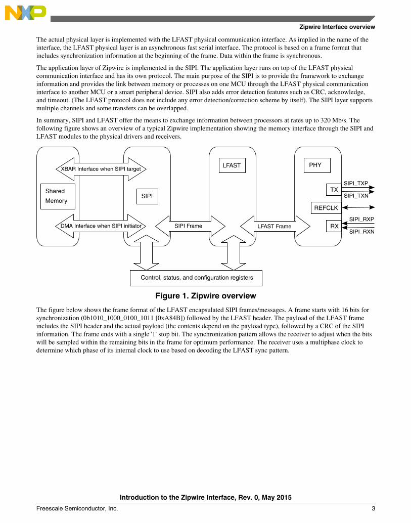
The actual physical layer is implemented with the LFAST physical communication interface. As implied in the name of theinterface, the LFAST physical layer is an asynchronous fast serial interface. The protocol is based on a frame format thatincludes synchronization information at the beginning of the frame. Data within the frame is synchronous.
The application layer of Zipwire is implemented in the SIPI. The application layer runs on top of the LFAST physicalcommunication interface and has its own protocol. The main purpose of the SIPI is to provide the framework to exchangeinformation and provides the link between memory or processes on one MCU through the LFAST physical communicationinterface to another MCU or a smart peripheral device. SIPI also adds error detection features such as CRC, acknowledge,and timeout. (The LFAST protocol does not include any error detection/correction scheme by itself). The SIPI layer supportsmultiple channels and some transfers can be overlapped.
In summary, SIPI and LFAST offer the means to exchange information between processors at rates up to 320 Mb/s. Thefollowing figure shows an overview of a typical Zipwire implementation showing the memory interface through the SIPI andLFAST modules to the physical drivers and receivers.
LFAST PHY
TX
RX
REFCLK
SIPI_TXP
SIPI_TXN
SIPI_RXP
SIPI_RXN
Shared Memory
LFAST Frame
SIPI
Control, status, and configuration registers
SIPI FrameDMA Interface when SIPI initiator
XBAR Interface when SIPI target
Figure 1. Zipwire overview
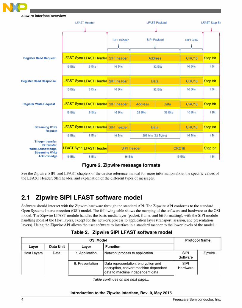
The figure below shows the frame format of the LFAST encapsulated SIPI frames/messages. A frame starts with 16 bits forsynchronization (0b1010_1000_0100_1011 [0xA84B]) followed by the LFAST header. The payload of the LFAST frameincludes the SIPI header and the actual payload (the contents depend on the payload type), followed by a CRC of the SIPIinformation. The frame ends with a single '1' stop bit. The synchronization pattern allows the receiver to adjust when the bitswill be sampled within the remaining bits in the frame for optimum performance. The receiver uses a multiphase clock todetermine which phase of its internal clock to use based on decoding the LFAST sync pattern.
Zipwire Interface overview
Introduction to the Zipwire Interface, Rev. 0, May 2015
LFAST Sync LFAST Header SIPI header CRC16 Stop bitAddress Data
32 Bits
Register Write Request
LFAST Sync LFAST Header SIPI header CRC16 Stop bit
16 Bits
Trigger transfer, ID transfer,
Write Acknowledge, Streaming Write
Acknowledge
LFAST Sync Stop bitStreaming Write Request
SIPI header CRC16Data
256 bits (32 Bytes)
SIPI CRCSIPI Payload
LFAST Header
8 Bits16 Bits
16 Bits8 Bits16 Bits
16 Bits8 Bits16 Bits
16 Bits
16 Bits8 Bits16 Bits
1 Bit16 Bits
16 Bits 1 Bit
16 Bits 1 Bit32 Bits
32 Bits 16 Bits 1 Bit
32 Bits 16 Bits 1 Bit
LFAST Header LFAST Payload
8 Bits16 Bits
Figure 2. Zipwire message formats
See the Zipwire, SIPI, and LFAST chapters of the device reference manual for more information about the specific values ofthe LFAST Header, SIPI header, and explanation of the different types of messages.
2.1 Zipwire SIPI LFAST software modelSoftware should interact with the Zipwire hardware through the standard API. The Zipwire API conforms to the standardOpen Systems Interconnection (OSI) model. The following table shows the mapping of the software and hardware to the OSImodel. The Zipwire LFAST module handles the basic media layer (packet, frame, and bit formatting), with the SIPI modulehandling most of the Host layers, except for the network process to application layer (transport, session, and presentationlayers). Using the Zipwire API allows the user software to interface in a standard manner to the lower levels of the model.
Table 2. Zipwire SIPI LFAST software model
OSI Model Protocol Name
Layer Data Unit Layer Function
Host Layers Data 7. Application Network process to application SIPISoftware
Zipwire
6. Presentation Data representation, encryption anddecryption, convert machine dependentdata to machine independent data
SIPIHardware
Table continues on the next page...
Zipwire Interface overview
Introduction to the Zipwire Interface, Rev. 0, May 2015
4 Freescale Semiconductor, Inc.
Table 2. Zipwire SIPI LFAST software model (continued)
OSI Model Protocol Name
Layer Data Unit Layer Function
5. Session Inter-host communication, managingsessions between applications
Segment 4. Transport End-to-end connections, reliability and flowcontrol
Media Layers Packet 3. Network Path determination and logical addressing LFAST
Frame 2. Data Link Physical addressing
Bit 1. Physical Media, signal and binary transmission
2.2 Typical Zipwire example overviewThe simplest example of a Zipwire interface is two MPC5777M microcontrollers communicating to each other (See thefigure below). Device 1 wants to write a memory location of Device 2.
1. The SIPI module, acting as the initiator, of the first MCU will use the DMA to acquire data to be sent from memory.This is done via software initialization.
2. Once the data registers are full, the initiator SIPI will automatically construct a frame indicating the operation toperform, the address to be written, the data to write, and a CRC. This is handled by the SIPI module in hardware.
3. This SIPI frame will then be sent by the hardware o the LFAST module and the module will embed the SIPI framewithin a greater LFAST compliant frame that will be sent through the physical interface.
4. The LFAST frame will be received by the second MCU, acting as a target node. The LFAST will then decompose theframe back into a SIPI understandable frame and send it to the SIPI. This is handled in hardware.
5. The SIPI target will verify that the message is correct and use the XBAR master interface to modify the data at therequested address. Once completed, the SIPI target will send back a write acknowledge message to the initiator. This isall handled by the Zipwire hardware.
6. Once the acknowledge has been received by the initiator, the DMA on the first device can start another operation untilthe desired amount of data has been written to the target MCU.
DEVICE 1
Shared Memory
DEVICE 2
Shared Memory
LFAST LFASTSIPI SIPI
Figure 3. Typical Zipwire application
Zipwire Interface overview
Introduction to the Zipwire Interface, Rev. 0, May 2015
Freescale Semiconductor, Inc. 5
3 Zipwire examplesThis section describes some basic examples of using the Zipwire driver. Simple functions were written to show the basicoperations of the Zipwire interface, including determining the remote device connected and performing simple operations tothe remote device over the Zipwire link.
Each of the examples is set up as a separate example and each contains both the Master and the Slave software. Each includescalls to the Zipwire API routines. The Zipwire API is included in this document as an appendix.
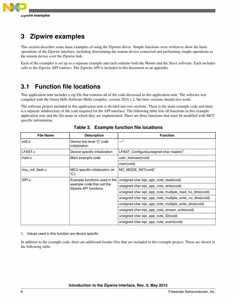
3.1 Function file locationsThis application note includes a zip file that contains all of the code discussed in this application note. The software wascompiled with the Green Hills Software Multi compiler, version 2014.1.2, but later versions should also work.
The software project included in this application note is divided into two sections. There is the main example code and thereis a separate subdirectory of the code required for the API interface. The following table lists all functions in this exampleapplication note and the file name in which they are implemented. There are three functions that must be modified with MCUspecific information.
Table 3. Example function file locations
File Name Description Function
crt0.s Device low level 'C' codeinitialization
—1
LFAST.c Device specific initialization LFAST_Configure(unsigned char master)1
main.c Main example code user_testcase(void)
main(void)
mcu_init_flash.c MCU specific initialization (in'C')
MC_MODE_INIT(void)1
SIPI.c Example functions used in theexample code that call theZipwire API functions
1. Values used in this function are device specific
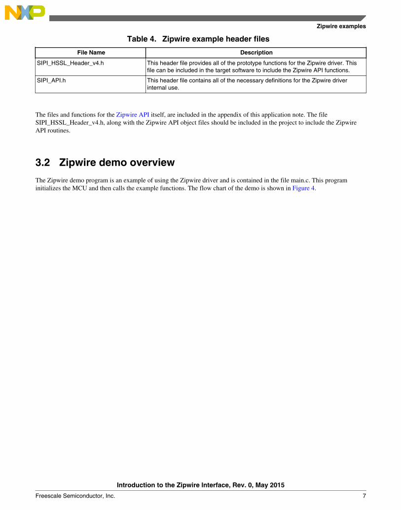
In addition to the example code, there are additional header files that are included in this example project. These are shown inthe following table.
Zipwire examples
Introduction to the Zipwire Interface, Rev. 0, May 2015
6 Freescale Semiconductor, Inc.
Table 4. Zipwire example header files
File Name Description
SIPI_HSSL_Header_v4.h This header file provides all of the prototype functions for the Zipwire driver. Thisfile can be included in the target software to include the Zipwire API functions.
SIPI_API.h This header file contains all of the necessary definitions for the Zipwire driverinternal use.
The files and functions for the Zipwire API itself, are included in the appendix of this application note. The fileSIPI_HSSL_Header_v4.h, along with the Zipwire API object files should be included in the project to include the ZipwireAPI routines.
3.2 Zipwire demo overview
The Zipwire demo program is an example of using the Zipwire driver and is contained in the file main.c. This programinitializes the MCU and then calls the example functions. The flow chart of the demo is shown in Figure 4.
Zipwire examples
Introduction to the Zipwire Interface, Rev. 0, May 2015
Freescale Semiconductor, Inc. 7
Send multiple write requests and verifydata was written correctly
Configure LFAST
Configure SIPI Channel
Send read request and verify the readvalues are what is expected
Send write request and verify that datawas written to the address
Send multiple read requests using CPU andverify the read values are what is expected
Send multiple write requests using DMA supportand verify that data was written correctly
Stream write a series of words and read backto verify data was streamed correctly
Send ID command and verify theID was received
Verify that a trigger event can beinitiated using the SIPI interface
Perform soft reset of SIPI module
user_testcase
MC_MODE_INIT
Figure 4. Zipwire Demo Code Flow Chart
The demo consists of several functions that are called from the demo. These functions are listed in Table 5.
Table 5. Demo function overview
Function Description
sipi_app_note_read Exercises the SIPI_read() and SIPI_read_channel_data functions to send a readrequest and verifies that the read values are the expected values.
sipi_app_note_write Exercises the SIPI_write(), SIPI_read() and SIPI_read_channel_data functions tosend a write request and then verify that the address was actually written.
sipi_app_note_ID Exercises the SIPI_ID() and SIPI_read_channel_data functions to send the IDcommand and read the CADR to verify that the ID was received.
sipi_app_note_event Exercises SIPI_Trigger() to verify that a trigger event can be initiated using the SIPIinterface.
sipi_app_note_multiple_read_no_dma Exercises SIPI_multiple_read() without using DMA support, each array will be readusing CPU and the read contents will be verified.
Table continues on the next page...
Zipwire examples
Introduction to the Zipwire Interface, Rev. 0, May 2015
8 Freescale Semiconductor, Inc.
Table 5. Demo function overview (continued)
Function Description
sipi_app_note_multiple_write_no_dma Exercises SIPI_multiple_write() and SIPI_multiple_read() to send multiple writerequests, once completed will read the written content to verify that the data waswritten correctly.
sipi_app_note_multiple_write_dma Exercises SIPI_multiple_write() using DMA support and SIPI_multiple_read() tosend multiple write requests, once completed will read the written content to verifythat the data was written correctly.
sipi_app_note_stream_write Exercises SIPI_stream_transfer() and SIPI_multiple_read() to stream write a seriesof words and then read them back to verify the data.
3.2.1 Function indexThe following table shows the functions used in the SIPI application note demo.
3.2.2 Function MC_MODE_INITThis function initializes the MPC5777M processor. It sets up the phase lock loop to set the device operating frequency, theperipheral clock frequencies, and enables all of the peripheral modules in the different "RUN" modes. It then performs amode change to enable the clocks and enable all cores of the device.
The function must be tailored for the target system and environment, including the device crystal frequency.
NOTEThe Zipwire clock is set up in the file LFAST.c.
Prototype: void MC_MODE_INIT(void);
Zipwire examples
Introduction to the Zipwire Interface, Rev. 0, May 2015
Freescale Semiconductor, Inc. 9
3.2.3 Function user_testcaseThe user testcase is the actual example code and calls most of the other functions of the Zipwire example code. The flow ofthis section is shown in Figure 4.
Prototype: void user_testcase(void);
3.2.4 Function LFAST_ConfigureConfigures the LFAST as either a Master or a Slave, sets the clocks and bus speeds, and configures the pins to set the LFASTlink.
unsigned char master input defines whether to configure the LFAST node as master orslave.
3.2.5 Function sipi_app_note_IDExercises the SIPI_ID() and SIPI_read_channel_data functions to send the ID command and read the CDR to verify that theID was received.
Prototype: unsigned char sipi_app_note_ID(void);
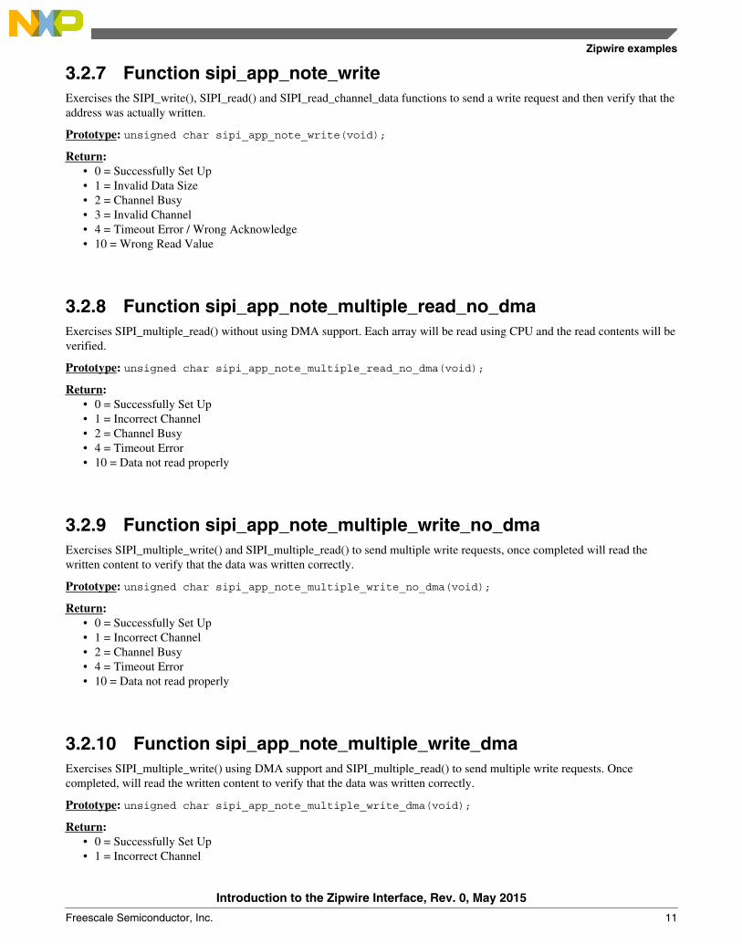
Return:• 0 = Successfully Set Up• 2 = Channel Busy• 3 = Invalid Channel• 4 = Timeout Error• 10 = ID Not received properly
3.2.6 Function sipi_app_note_readExercises the SIPI_read() and SIPI_read_channel_data() functions to send a read request and verifies that the read values arethe expected values.
Introduction to the Zipwire Interface, Rev. 0, May 2015
10 Freescale Semiconductor, Inc.
3.2.7 Function sipi_app_note_writeExercises the SIPI_write(), SIPI_read() and SIPI_read_channel_data functions to send a write request and then verify that theaddress was actually written.
3.2.8 Function sipi_app_note_multiple_read_no_dmaExercises SIPI_multiple_read() without using DMA support. Each array will be read using CPU and the read contents will beverified.
Return:• 0 = Successfully Set Up• 1 = Incorrect Channel• 2 = Channel Busy• 4 = Timeout Error• 10 = Data not read properly
3.2.9 Function sipi_app_note_multiple_write_no_dmaExercises SIPI_multiple_write() and SIPI_multiple_read() to send multiple write requests, once completed will read thewritten content to verify that the data was written correctly.
Return:• 0 = Successfully Set Up• 1 = Incorrect Channel• 2 = Channel Busy• 4 = Timeout Error• 10 = Data not read properly
3.2.10 Function sipi_app_note_multiple_write_dmaExercises SIPI_multiple_write() using DMA support and SIPI_multiple_read() to send multiple write requests. Oncecompleted, will read the written content to verify that the data was written correctly.
Return:• 0 = Successfully Set Up• 1 = Incorrect Channel
Zipwire examples
Introduction to the Zipwire Interface, Rev. 0, May 2015
Freescale Semiconductor, Inc. 11
• 2 = Channel Busy• 4 = Timeout Error• 10 = Data not read properly
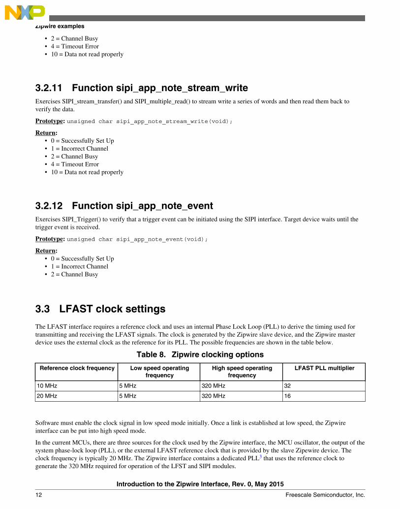
3.2.11 Function sipi_app_note_stream_writeExercises SIPI_stream_transfer() and SIPI_multiple_read() to stream write a series of words and then read them back toverify the data.
Return:• 0 = Successfully Set Up• 1 = Incorrect Channel• 2 = Channel Busy• 4 = Timeout Error• 10 = Data not read properly
3.2.12 Function sipi_app_note_eventExercises SIPI_Trigger() to verify that a trigger event can be initiated using the SIPI interface. Target device waits until thetrigger event is received.
The LFAST interface requires a reference clock and uses an internal Phase Lock Loop (PLL) to derive the timing used fortransmitting and receiving the LFAST signals. The clock is generated by the Zipwire slave device, and the Zipwire masterdevice uses the external clock as the reference for its PLL. The possible frequencies are shown in the table below.
Table 8. Zipwire clocking options
Reference clock frequency Low speed operatingfrequency
High speed operatingfrequency
LFAST PLL multiplier
10 MHz 5 MHz 320 MHz 32
20 MHz 5 MHz 320 MHz 16
Software must enable the clock signal in low speed mode initially. Once a link is established at low speed, the Zipwireinterface can be put into high speed mode.
In the current MCUs, there are three sources for the clock used by the Zipwire interface, the MCU oscillator, the output of thesystem phase-lock loop (PLL), or the external LFAST reference clock that is provided by the slave Zipewire device. Theclock frequency is typically 20 MHz. The Zipwire interface contains a dedicated PLL3 that uses the reference clock togenerate the 320 MHz required for operation of the LFST and SIPI modules.
Zipwire examples
Introduction to the Zipwire Interface, Rev. 0, May 2015
12 Freescale Semiconductor, Inc.
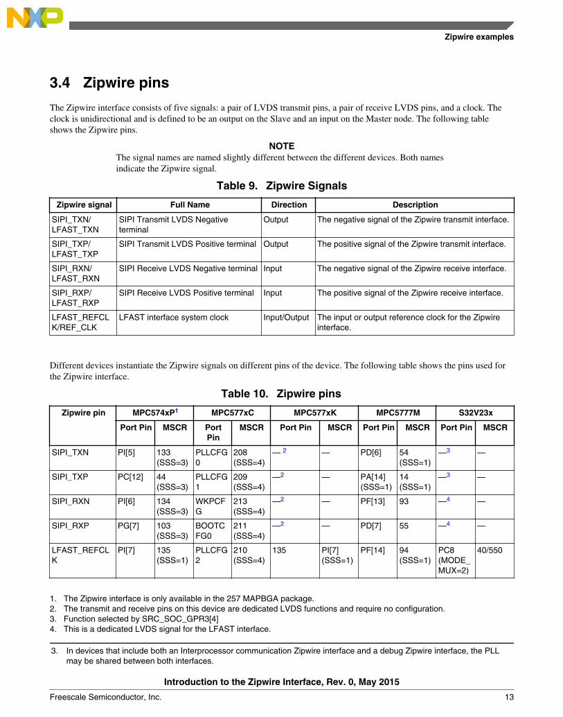
3.4 Zipwire pins
The Zipwire interface consists of five signals: a pair of LVDS transmit pins, a pair of receive LVDS pins, and a clock. Theclock is unidirectional and is defined to be an output on the Slave and an input on the Master node. The following tableshows the Zipwire pins.
NOTEThe signal names are named slightly different between the different devices. Both namesindicate the Zipwire signal.
Table 9. Zipwire Signals
Zipwire signal Full Name Direction Description
SIPI_TXN/LFAST_TXN
SIPI Transmit LVDS Negativeterminal
Output The negative signal of the Zipwire transmit interface.
SIPI_TXP/LFAST_TXP
SIPI Transmit LVDS Positive terminal Output The positive signal of the Zipwire transmit interface.
SIPI_RXN/LFAST_RXN
SIPI Receive LVDS Negative terminal Input The negative signal of the Zipwire receive interface.
SIPI_RXP/LFAST_RXP
SIPI Receive LVDS Positive terminal Input The positive signal of the Zipwire receive interface.
LFAST_REFCLK/REF_CLK
LFAST interface system clock Input/Output The input or output reference clock for the Zipwireinterface.
Different devices instantiate the Zipwire signals on different pins of the device. The following table shows the pins used forthe Zipwire interface.
1. The Zipwire interface is only available in the 257 MAPBGA package.2. The transmit and receive pins on this device are dedicated LVDS functions and require no configuration.3. Function selected by SRC_SOC_GPR3[4]4. This is a dedicated LVDS signal for the LFAST interface.
3. In devices that include both an Interprocessor communication Zipwire interface and a debug Zipwire interface, the PLLmay be shared between both interfaces.
Zipwire examples
Introduction to the Zipwire Interface, Rev. 0, May 2015
Freescale Semiconductor, Inc. 13
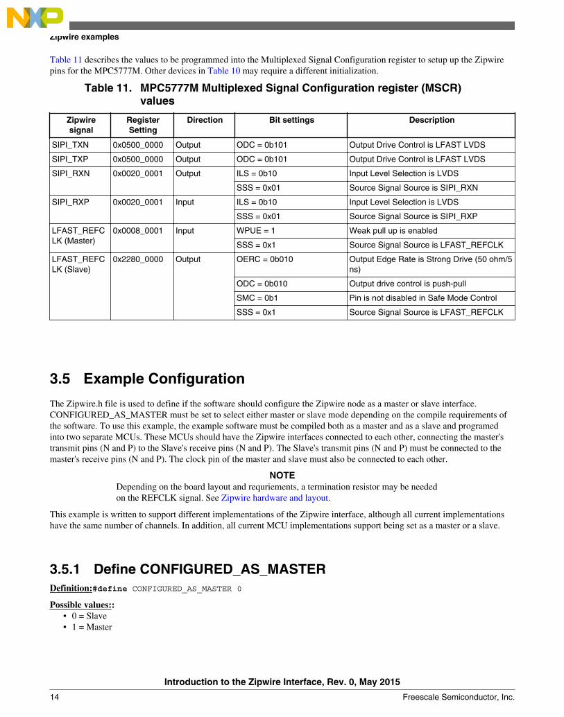
Table 11 describes the values to be programmed into the Multiplexed Signal Configuration register to setup up the Zipwirepins for the MPC5777M. Other devices in Table 10 may require a different initialization.
Table 11. MPC5777M Multiplexed Signal Configuration register (MSCR)values
Zipwiresignal
RegisterSetting
Direction Bit settings Description
SIPI_TXN 0x0500_0000 Output ODC = 0b101 Output Drive Control is LFAST LVDS
SIPI_TXP 0x0500_0000 Output ODC = 0b101 Output Drive Control is LFAST LVDS
SIPI_RXN 0x0020_0001 Output ILS = 0b10 Input Level Selection is LVDS
SSS = 0x01 Source Signal Source is SIPI_RXN
SIPI_RXP 0x0020_0001 Input ILS = 0b10 Input Level Selection is LVDS
SSS = 0x01 Source Signal Source is SIPI_RXP
LFAST_REFCLK (Master)
0x0008_0001 Input WPUE = 1 Weak pull up is enabled
SMC = 0b1 Pin is not disabled in Safe Mode Control
SSS = 0x1 Source Signal Source is LFAST_REFCLK
3.5 Example Configuration
The Zipwire.h file is used to define if the software should configure the Zipwire node as a master or slave interface.CONFIGURED_AS_MASTER must be set to select either master or slave mode depending on the compile requirements ofthe software. To use this example, the example software must be compiled both as a master and as a slave and programedinto two separate MCUs. These MCUs should have the Zipwire interfaces connected to each other, connecting the master'stransmit pins (N and P) to the Slave's receive pins (N and P). The Slave's transmit pins (N and P) must be connected to themaster's receive pins (N and P). The clock pin of the master and slave must also be connected to each other.
NOTEDepending on the board layout and requriements, a termination resistor may be neededon the REFCLK signal. See Zipwire hardware and layout.
This example is written to support different implementations of the Zipwire interface, although all current implementationshave the same number of channels. In addition, all current MCU implementations support being set as a master or a slave.
Introduction to the Zipwire Interface, Rev. 0, May 2015
14 Freescale Semiconductor, Inc.
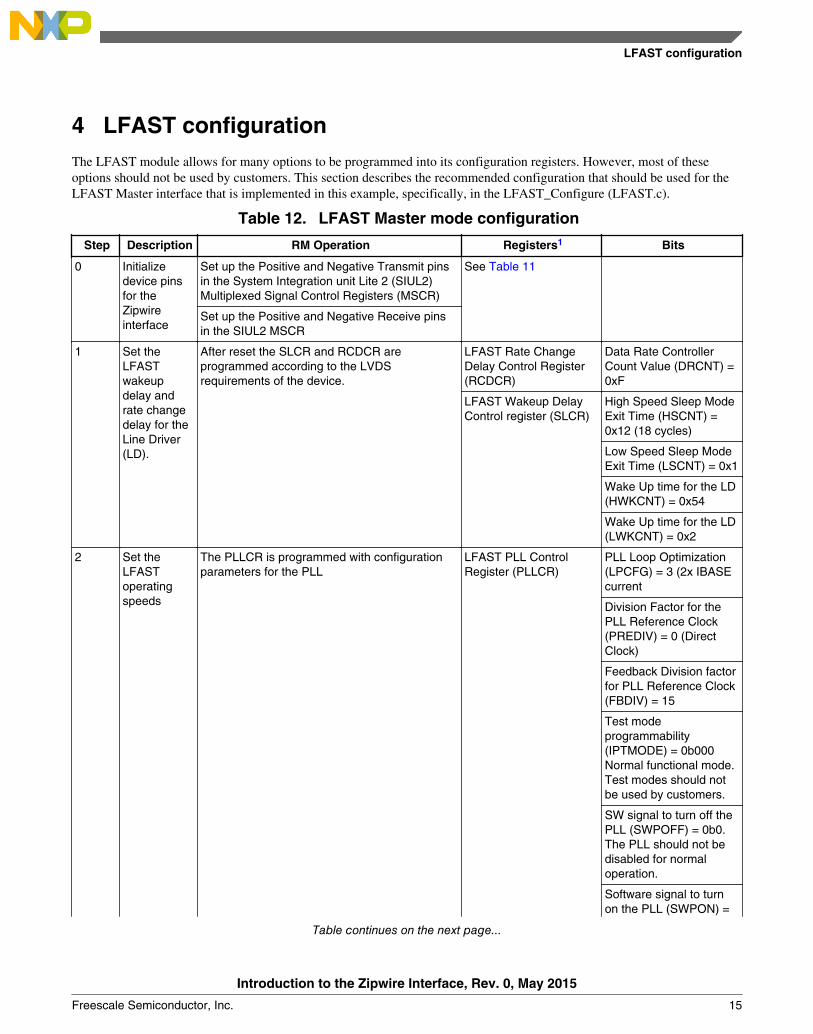
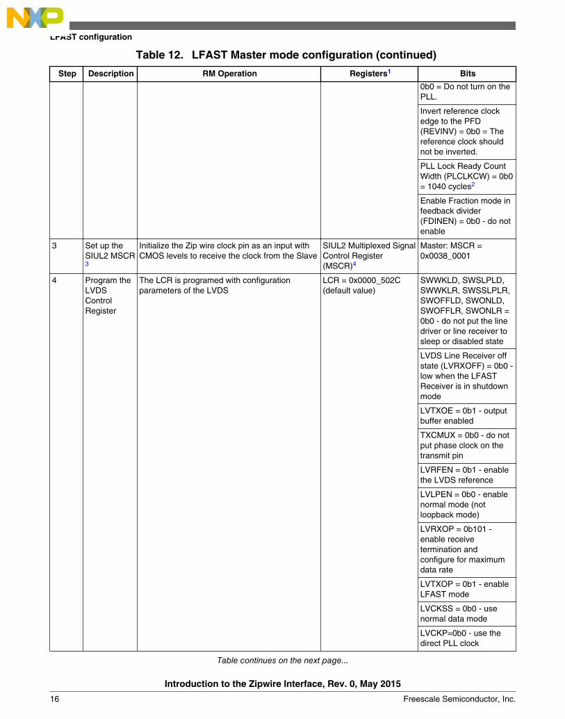
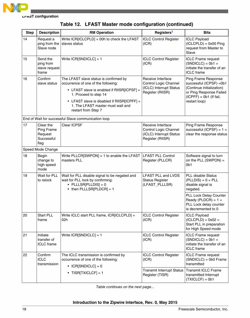
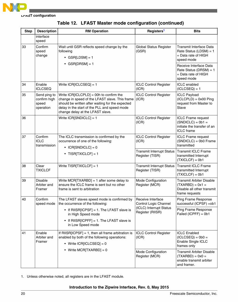
4 LFAST configurationThe LFAST module allows for many options to be programmed into its configuration registers. However, most of theseoptions should not be used by customers. This section describes the recommended configuration that should be used for theLFAST Master interface that is implemented in this example, specifically, in the LFAST_Configure (LFAST.c).
Table 12. LFAST Master mode configuration
Step Description RM Operation Registers1 Bits
0 Initializedevice pinsfor theZipwireinterface
Set up the Positive and Negative Transmit pinsin the System Integration unit Lite 2 (SIUL2)Multiplexed Signal Control Registers (MSCR)
See Table 11
Set up the Positive and Negative Receive pinsin the SIUL2 MSCR
1 Set theLFASTwakeupdelay andrate changedelay for theLine Driver(LD).
After reset the SLCR and RCDCR areprogrammed according to the LVDSrequirements of the device.
LFAST Rate ChangeDelay Control Register(RCDCR)
Data Rate ControllerCount Value (DRCNT) =0xF
LFAST Wakeup DelayControl register (SLCR)
High Speed Sleep ModeExit Time (HSCNT) =0x12 (18 cycles)
Low Speed Sleep ModeExit Time (LSCNT) = 0x1
Wake Up time for the LD(HWKCNT) = 0x54
Wake Up time for the LD(LWKCNT) = 0x2
2 Set theLFASToperatingspeeds
The PLLCR is programmed with configurationparameters for the PLL
LFAST PLL ControlRegister (PLLCR)
PLL Loop Optimization(LPCFG) = 3 (2x IBASEcurrent
Division Factor for thePLL Reference Clock(PREDIV) = 0 (DirectClock)
Wait until GSR reflects speed change by thefollowing
• GSR[LDSM] = 1
• GSR[DRSM] = 1
Global Status Register(GSR)
Transmit Interface DataRate Status (LDSM) = 1= Data rate of HIGHspeed mode
Receive Interface DataRate Status (DRSM) = 1= Data rate of HIGHspeed mode
34 EnableICLCSEQ
Write ICR[ICLCSEQ] = 1 ICLC Control Register(ICR)
ICLC enabled(ICLCSEQ) = 1
35 Send ping toconfirm highspeedoperation
Write ICR[ICLCPLD] = 00h to confirm thechange in speed of the LFAST slave. This frameshould be written after waiting for the expecteddelay in the start of the PLL and speed modechange delay at the LFAST slave.
ICLC Control Register(ICR)
ICLC Payload(ICLCPLD) = 0x00 Pingrequest from Master toSlave
36 Write ICR[SNDICLC] = 1 ICLC Control Register(ICR)
ICLC Frame request(SNDICLC) = 0b1 =initiate the transfer of anICLC frame
37 ConfirmICLCtransmission
The ICLC transmission is confirmed by theoccurrence of one of the following:
1. Unless otherwise noted, all registers are in the LFAST module.
LFAST configuration
Introduction to the Zipwire Interface, Rev. 0, May 2015
20 Freescale Semiconductor, Inc.
2. It is possible that this value could be reduced, however, it is dependent on the actual crystal and system frequencies, aswell as board design parameters such as PLL stability, power supply stability, board layout, and other operating conditions.
3. The SIUL2 module is labeled as SIU in some devices.4. The exact MSCR register and value will depend on the device type and whether the device is being programmed for
Master or Slave operation.
When operating in slave mode, the Zipwire interface requires much less initialization. The following table shows theconfiguration of the MCU for the LFAST Slave interface.
Table 13. LFAST Slave mode configuration
Step Description RM Operation Registers1 Bits
0 Initializedevice pinsfor theZipwireinterface
Set up the Positive and Negative Transmit pinsin the System Integration Unit Lite 2 (SIUL2)Multiplexed Signal Control Registers (MSCR)
See Table 11
Set up the Positive and Negative Receive pinsin the SIUL2 MSCR
1 Set theLFASTwakeupdelay andrate changedelay for theLine Driver(LD).
After reset the SLCR and RCDCR areprogrammed according to the LVDSrequirements of the device.
LFAST Rate ChangeDelay Control Register(RCDCR)
Data Rate ControllerCount Value (DRCNT) =0xF
LFAST Wakeup DelayControl register (SLCR)
High Speed Sleep ModeExit Time (HSCNT) =0x12 (18 cycles)
Low Speed Sleep ModeExit Time (LSCNT) = 0x1
Wake Up time for the LD(HWKCNT) = 0x54
Wake Up time for the LD(LWKCNT) = 0x2
2 Set theLFASToperatingspeeds
The PLLCR is programmed with configurationparameters for the PLL
LFAST PLL ControlRegister (PLLCR)
PLL Loop Optimization(LPCFG) = 3 (2x IBASEcurrent
Division Factor for thePLL Reference Clock(PREDIV) = 0 (DirectClock)
ICLC frame for LFASTSlaves Rx Interface fastmode switch received(ICRFF) = 1 = Interruptevent has occurred
Speed Control Register(SCR)
Receiver Data Rate(TDR) = 0b1 = Data rateof Rx block is 312/320Mb/s
1. Unless otherwise noted, all registers are in the LFAST module.2. The SIUL2 module is labeled as SIU in some devices.3. The exact MSCR register and value will depend on the device type and whether the device is being programmed for
Master or Slave operation.
5 Zipwire hardware and layout
Zipwire hardware and layout
Introduction to the Zipwire Interface, Rev. 0, May 2015
24 Freescale Semiconductor, Inc.
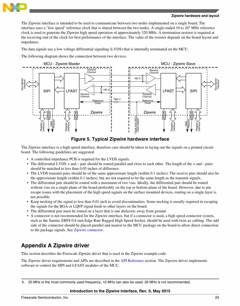
The Zipwire interface is intended to be used to communicate between two nodes implemented on a single board. Theinterface uses a "low speed" reference clock that is shared between the two nodes. A single-ended 10 to 264 MHz referenceclock is used to generate the Zipwire high speed operation of approximately 320 MHz. A termination resistor is required atthe receiving end of the clock for best performance of the interface. The value of the resistor depends on the board layout andimpedance.
The data signals use a low voltage differential signaling (LVDS) that is internally terminated on the MCU.
The following diagram shows the connection between two devices.
+
–100 ΩSIPIB
us M
aste
rIn
terf
ace
Reg
iste
rIn
terf
ace
Inte
rrup
tR
eque
stD
MA
Req
uest
Reg
iste
rIn
terf
ace
Inte
rrup
tR
eque
st
LFASTReceiveChannel
TransmitChannel
ReferenceClock
MCU - Zipwire Master MCU - Zipwire Slave
100 Ω+
–
SIPI Bus
Mas
ter
Inte
rfac
e
Reg
iste
rIn
terf
ace
Inte
rrup
tR
eque
st
DM
AR
eque
st
Reg
iste
rIn
terf
ace
Inte
rrup
tR
eque
st
LFAST
ReceiveChannel
TransmitChannel
ReferenceClock
Clo
ck fr
om M
CU
cloc
k sy
stem
Zipwire Zipwire
TBD Ω
Figure 5. Typical Zipwire hardware interface
The Zipwire interface is a high-speed interface, therefore care should be taken in laying out the signals on a printed circuitboard. The following guidelines are suggested.
• A controlled impedance PCB is required for the LVDS signals.• The differential LVDS + and – pair should be routed parallel and close to each other. The length of the + and - pairs
should be matched to less than 0.05 inches of difference.• The LVDS transmit pairs should be of the same approximate length (within 0.1 inches). The receive pins should also be
the approximate length (within 0.1 inches), but are not required to be the same length as the transmit signals.• The differential pair should be routed with a maximum of two vias. Ideally, the differential pair should be routed
without vias on a single plane of the board preferably on the top or bottom plane of the board. However, due to pinescape issues with the placement of the high speed signals on the surface mounted devices, routing on a single layer isnot possible.
• Keep necking of the signal to less than 0.01 inch to avoid discontinuities. Some necking is usually required in escapingthe signals for the BGA or LQFP signal feeds to other layers on the board.
• The differential pair must be routed on a layer that is one dielectric away from ground.• A connector is not recommended for the Zipwire interface, but if a connector is used, a high speed connector system,
such as the Samtec ERF8 0.8 mm Edge Rate Rugged High Speed Socket, should be used with twin-ax cabling. The oddside of the connector should be placed parallel and nearest to the MCU package on the board to allow direct connectionto the package signals. See Zipwire connector.
Appendix A Zipwire driverThis section describes the Freescale Zipwire driver that is used in the Zipwire example code.
The Zipwire driver requirements and APIs are described in the API Reference section. The Zipwire driver implementssoftware to control the SIPI and LFAST modules of the MCU.
4. 20 MHz is the most commonly used frequency, 10 MHz can also be used. 26 MHz is not recommended.
Zipwire hardware and layout
Introduction to the Zipwire Interface, Rev. 0, May 2015
Freescale Semiconductor, Inc. 25
A.1 OverviewThe Zipwire Inter-processor Communication Interface is a combination of the Serial Interprocessor Interface module and theLVDS Fast Asynchronous Serial Transmission interface. This provides a standard interface for communicating at a highspeed between two microcontrollers or between a microcontroller and a smart peripheral. This driver provides a standardApplication Programming Interface to use the Zipwire interface in user written software.
A.2 About this AppendixThis Technical Reference Appendix employs the following typographical conventions:
• boldface type: Bold is used for important terms, notes and warnings.• courier font: Courier typeface is used for code snippets in the text. Note that C language modifiers such “const” or
“volatile” are sometimes omitted to improve readability of the presented code.
Notes and warnings are shown below:
NoteThis is a note.
A.3 Zipwire Driver APIThe Zipwire driver API implements the basic functions required to use the Zipwire interface as detailed in this document.
A.3.1 Driver Design SummaryThe Zipwire driver API provides services for the following features:
• LOW LEVEL• LFAST Initialization for High Speed mode and Low Speed mode (20 MHz and 10 MHz)• SIUL2 configuration for Zipwire pins and clock signal for both, initiator and target mode.• Clock Initialization for AUXCLOCK 1 (LFAST exclusive clock)
• API LEVEL• SIPI initiator and Target Initializations• SIPI Mode Changes• SIPI Channel Initialization.• Read Transfer Operation• Write Transfer Operation (DMA Supported)• Stream Transfer Operation• Event Trigger Operation• ID Operation
All of the Zipwire API functions are included in a single 'C' source code file.
Overview
Introduction to the Zipwire Interface, Rev. 0, May 2015
26 Freescale Semiconductor, Inc.
Table A-1. Zipwire function file locations
File Name Description Function
SIPI_HSSL_API.c Zipwire API functions uint8_t SIPI_read(DATA_TEMPLATE_t data_address,CHANNEL_t channel, uint8_t injected_error)
In addition to the API code, there are additional header files that are included in the Zipwire API. These are shown in thefollowing table.
Table A-2. Zipwire API header files
File Name Description
SIPI_HSSL_Header_v4.h This header file provides all of the prototype functions for the Zipwire driver. Thisfile can be included in the target software to include the Zipwire API functions.
SIPI_API.h This header file contains all of the necessary definitions for the Zipwire driverinternal use.
A.3.2 API ReferenceThis section contains description of the Zipwire driver API.
Zipwire Driver API
Introduction to the Zipwire Interface, Rev. 0, May 2015
Freescale Semiconductor, Inc. 27
A.3.2.1 Function IndexTable A-3. Quick Function Reference
A.3.2.2 Function SIPI_resetPerforms soft reset of module. Clears all status and error registers, returning the module to 'Disabled'. Any transfers inprogress when reset is called will immediately end. Returns '0' if successful, error code otherwise.
Prototype: uint8_t SIPI_reset(void);
Return:• 0 = Successfully Reset on Module
Zipwire Driver API
Introduction to the Zipwire Interface, Rev. 0, May 2015
28 Freescale Semiconductor, Inc.
A.3.2.3 Function SIPI_init_TARGETInitializes Target side of SIPI module, setting SIPI_MCR[TEN], SIPI_MAXCR and SIPI_ARR. Returns '0' if successful,error code otherwise.
uint32_t max_count input Maximum address count value of target node
uint32_t reload_address input Reload value for the address counter at target node
uint8_t Add_Inc input Integer representation of Address Increment/Decrement bits.Can be 0,1,2 or 3 for 'No change, Increment Address by 4,Decrement Address by 4, or Not Used respectively.
Return:• 0 = Successfully Set Up Target Node• 1 = Address Increment Error• 2 = Max Count Address Conflicts with Address Count
A.3.2.4 Function SIPI_init_channelInitializes SIPI Channels. Sets up SIPI_CIRn registers. Will also need to set up interrupts/events to handle received packetsappropriately. Clears all errors and events associated with the channel. Returns '0' if successful, error code otherwise.
CHANNEL_t channel input SIPI Channel to use. Should be passed as 1 element ofCHANNEL array.
uint8_t mode input Sets the channel mode to be used. Set 0 - Run, 1 - Disabled,2 - clear error, 3 - stop request;
uint8_t error_int_enable input Set to 1 to enable error interrupts on the channel
uint8_t data_int_enable input Set to 1 to enable data interrupts on the channel
Return:• 0 = Successfully Set Up Channel• 1 = Incorrect Channel Mode• 2 = Incorrect Channel
Zipwire Driver API
Introduction to the Zipwire Interface, Rev. 0, May 2015
Freescale Semiconductor, Inc. 29
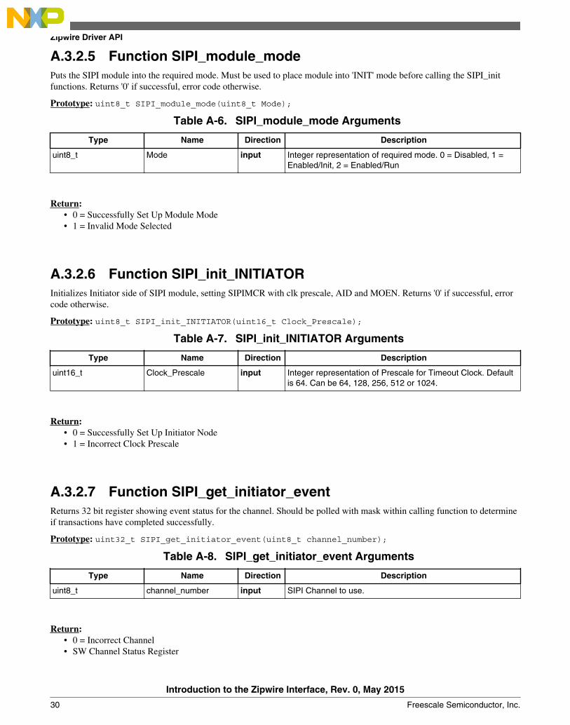
A.3.2.5 Function SIPI_module_modePuts the SIPI module into the required mode. Must be used to place module into 'INIT' mode before calling the SIPI_initfunctions. Returns '0' if successful, error code otherwise.
Return:• 0 = Successfully Set Up Module Mode• 1 = Invalid Mode Selected
A.3.2.6 Function SIPI_init_INITIATORInitializes Initiator side of SIPI module, setting SIPIMCR with clk prescale, AID and MOEN. Returns '0' if successful, errorcode otherwise.
uint16_t Clock_Prescale input Integer representation of Prescale for Timeout Clock. Defaultis 64. Can be 64, 128, 256, 512 or 1024.
Return:• 0 = Successfully Set Up Initiator Node• 1 = Incorrect Clock Prescale
A.3.2.7 Function SIPI_get_initiator_eventReturns 32 bit register showing event status for the channel. Should be polled with mask within calling function to determineif transactions have completed successfully.
Return:• 0 = Incorrect Channel• SW Channel Status Register
Zipwire Driver API
Introduction to the Zipwire Interface, Rev. 0, May 2015
30 Freescale Semiconductor, Inc.
A.3.2.8 Function SIPI_IDSends ID Request Frame to target. Stores received command in the address passed. Returns '0' if successful, error codeotherwise.
uint32_t * id_array input used as a dummy data to set CAR to initiate the transfer
CHANNEL_t channel input SIPI Channel to use. Should be passed as 1 element ofCHANNEL array.
Return:• 0 = Successfully Received Acknowledge and ID• 2 = Channel Busy• 3 = Invalid Channel• 4 = Timeout Error
A.3.2.9 Function SIPI_read_channel_dataReads channel data when a successful read reply / ID reply is received.
NOTEThe function will always return a 32 bit value. If 8 or 16 bit data is read, it will bereplicated as described in the RM. A relevant casting / mask operation may be requiredfor 8 and 16 bit read replies. Need to check for command completion and channel errorsbefore calling this function.
CHANNEL_t channel input SIPI Channel the received data used.
Return:• 0 = Invalid Channel• 32-bit value contained in Channel data register.
A.3.2.10 Function SIPI_readPerforms a single read transfer. Returns '0' if successful, error code otherwise. Stores read value in DATA_TEMPLATE_tpassed.
A.3.2.11 Function SIPI_multiple_readPerforms a direct read transfer. Returns '0' if successful, error code otherwise. Stores read values in struct pointed to. Shouldcall SIPI_read() to process each read in array.
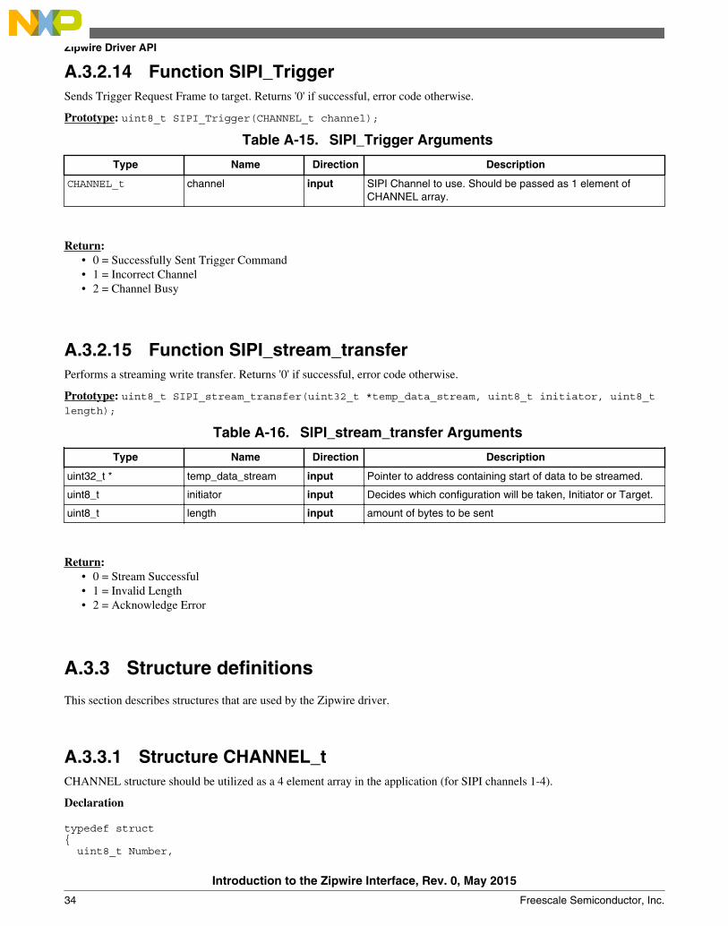
A.3.2.13 Function SIPI_multiple_writePerforms multiple transfers. Returns '0' if successful, error code otherwise. SIPI_write should be called to process eachseparate write in array, and poll for the SIPI_write_ack function to complete before moving to next message.
DATA_TEMPLATE_t * write_array input DATA_TEMPLATE_t structure which includes array containingwrite Address and Data to be written for each array record.
uint16_t array_length input Amount of data elements in array to be written.
CHANNEL_t channel input SIPI Channel to use. Should be passed as 1 element ofCHANNEL array.
uint8_t DMA_Enable input Selects whether DMA should be used for transfer or software.Software will form blocking function which will run until allwrites complete.
uint32_t * dma_array input receives a pointer to an array of integers that contains DMAfriendly structure
This section describes structures that are used by the Zipwire driver.
A.3.3.1 Structure CHANNEL_tCHANNEL structure should be utilized as a 4 element array in the application (for SIPI channels 1-4).
Declaration
typedef struct uint8_t Number,
Zipwire Driver API
Introduction to the Zipwire Interface, Rev. 0, May 2015
34 Freescale Semiconductor, Inc.
uint8_t Timeout CHANNEL_t;
Table A-17. Structure CHANNEL_t member description
Member Description
Number Defines the Zipwire Channel Number that will be used.
Timeout Can be used to hold if a specific channel request has timed out.
A.3.3.2 Structure DATA_TEMPLATE_tDATA_TEMPLATE structure should contain write Address and Data pointers for SIPI_write command,read Address pointerand Data size for SIPI_read.
Table A-18. Structure DATA_TEMPLATE_t member description
Member Description
Data Data that will be transferred
Address Holds the address where the data will be written or read from on target.
Size Specifies the size of the write and read values.
Appendix B Zipwire connectorIn most cases, the Zipwire interface will be implemented between two devices on the same printed circuit board (PCB). Forevaluation purposes, a connector may be desired. The tables below show the recommended connectors and the recommendedpin out for a Zipwire interface. The recommended connector is a 10-pin (5 position) from Samtec. Cable locks on each end ofthe connector are also grounded.
CAUTIONZipwire is intended to be used between two devices on the same printed circuit board.This connector and cable is only intended for evaluation of products and not for actualcustomer implementations.
The differential signals should ideally be implemented as twin-axial cables if a cable is used. When the devices are located onthe same board, the signals should be routed as matched impedance pairs.
Table B-1. Recommended Connector (Samtec part numbers)
Target connector ERF8-005-05.0-L-DV-L-TR
12 inch cross-over cable1 HDR-169378-xx2
1. Approximate length.
Introduction to the Zipwire Interface, Rev. 0, May 2015
Freescale Semiconductor, Inc. 35
2. xx is the revision number
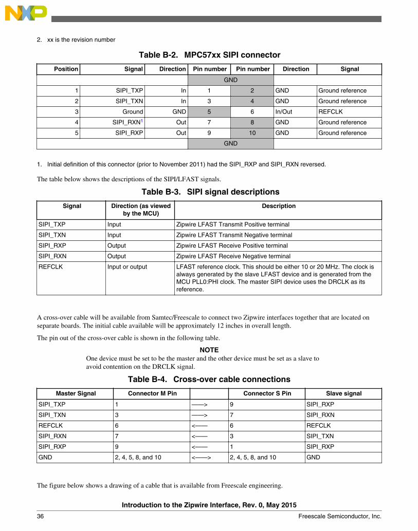
Table B-2. MPC57xx SIPI connector
Position Signal Direction Pin number Pin number Direction Signal
GND
1 SIPI_TXP In 1 2 GND Ground reference
2 SIPI_TXN In 3 4 GND Ground reference
3 Ground GND 5 6 In/Out REFCLK
4 SIPI_RXN1 Out 7 8 GND Ground reference
5 SIPI_RXP Out 9 10 GND Ground reference
GND
1. Initial definition of this connector (prior to November 2011) had the SIPI_RXP and SIPI_RXN reversed.
The table below shows the descriptions of the SIPI/LFAST signals.
REFCLK Input or output LFAST reference clock. This should be either 10 or 20 MHz. The clock isalways generated by the slave LFAST device and is generated from theMCU PLL0:PHI clock. The master SIPI device uses the DRCLK as itsreference.
A cross-over cable will be available from Samtec/Freescale to connect two Zipwire interfaces together that are located onseparate boards. The initial cable available will be approximately 12 inches in overall length.
The pin out of the cross-over cable is shown in the following table.
NOTEOne device must be set to be the master and the other device must be set as a slave toavoid contention on the DRCLK signal.
Table B-4. Cross-over cable connections
Master Signal Connector M Pin Connector S Pin Slave signal
SIPI_TXP 1 ——> 9 SIPI_RXP
SIPI_TXN 3 ——> 7 SIPI_RXN
REFCLK 6 <—— 6 REFCLK
SIPI_RXN 7 <—— 3 SIPI_TXN
SIPI_RXP 9 <—— 1 SIPI_RXP
GND 2, 4, 5, 8, and 10 <——> 2, 4, 5, 8, and 10 GND
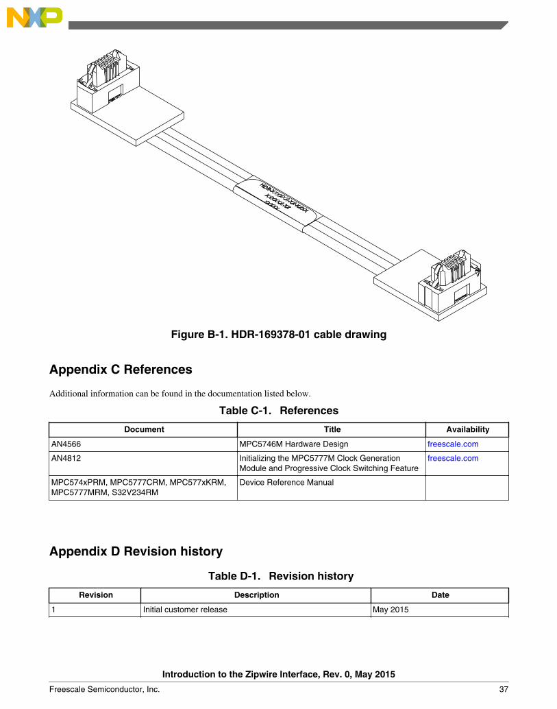
The figure below shows a drawing of a cable that is available from Freescale engineering.
Introduction to the Zipwire Interface, Rev. 0, May 2015
36 Freescale Semiconductor, Inc.
Figure B-1. HDR-169378-01 cable drawing
Appendix C References
Additional information can be found in the documentation listed below.
Table C-1. References
Document Title Availability
AN4566 MPC5746M Hardware Design freescale.com
AN4812 Initializing the MPC5777M Clock GenerationModule and Progressive Clock Switching Feature
Information in this document is provided solely to enable system andsoftware implementers to use Freescale products. There are no expressor implied copyright licenses granted hereunder to design or fabricateany integrated circuits based on the information in this document.Freescale reserves the right to make changes without further notice toany products herein.
Freescale makes no warranty, representation, or guarantee regardingthe suitability of its products for any particular purpose, nor doesFreescale assume any liability arising out of the application or use ofany product or circuit, and specifically disclaims any and all liability,including without limitation consequential or incidental damages.“Typical” parameters that may be provided in Freescale data sheetsand/or specifications can and do vary in different applications, andactual performance may vary over time. All operating parameters,including “typicals,” must be validated for each customer application bycustomer's technical experts. Freescale does not convey any licenseunder its patent rights nor the rights of others. Freescale sells productspursuant to standard terms and conditions of sale, which can be foundat the following address: freescale.com/SalesTermsandConditions.
Freescale, the Freescale logo, SafeAssure, and SafeAssure logo aretrademarks of Freescale Semiconductor, Inc., Reg. U.S. Pat. & Tm. Off.The Power Architecture and Power.org word marks and the Power andPower.org logos and related marks are trademarks and service markslicensed by Power.org. ARM and Cortex are registered trademarks ofARM Limited (or its subsidiaries) in the EU and/or elsewhere. mbed is atrademark of ARM Limited (or its subsidiaries) in the EU and/orelsewhere. All rights reserved. All other product or service names arethe property of their respective owners.