47

Introduction to Vector Control
of Permanent Magnet Synchronous Machinesusing
Energetic Macroscopic Representation
[email protected] Professor in Electrical Engineering
PhD - HdR
Arts et Métiers ParisTech – Lille - FranceL2EP – Control Team
ERASMUS MUNDUS MASTER STEPS
02&03/12/2013

3Pedagogical Outcomes
At the end of the lecture, students have to be able to:
Use a methodological approach to represent models ofelectrical systems in order to help the deduction of dedicatedcontrol schemes
Understand what are the variables of a Permanent MagnetSynchronous Machine (PMSM) to be controlled
Know, with the help of SIMULINK simulations, how to control aPMSM in the abc reference frame and what are the inherentlimitations
Know, with the help of SIMULINK simulations, how to control aPMSM in the dq reference frame and what are the necessarymathematical transformations to implement

4Agenda
• Models and Representations for the control of electrical systems• Modelling and Energetic Macroscopic Representation (EMR) of
Permanent Magnet Synchronous Machines (PMSM)• Principles of Inversion Based Control• Inversion Based Control of Permanent Magnet Synchronous
Machines (PMSM) – abc reference frame– Simulation with SIMULINK
• Inversion Based Control of Permanent Magnet SynchronousMachines (PMSM) – dq reference frame– Simulation with SIMULINK
5Models and Representations
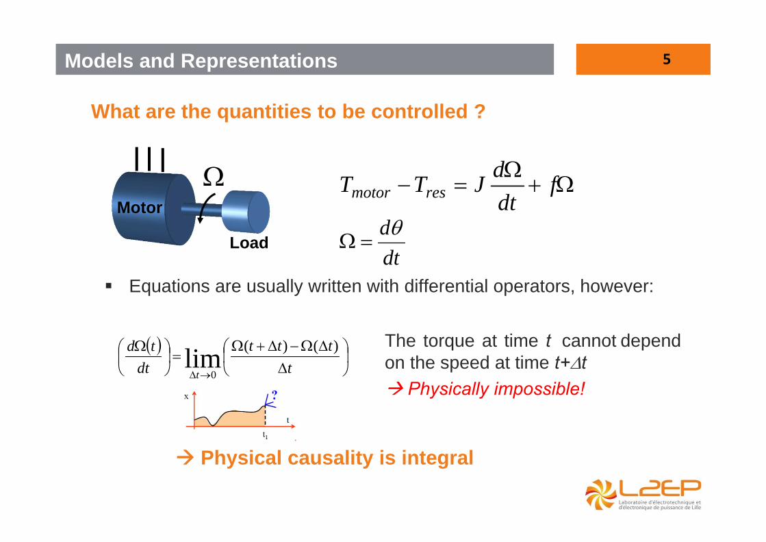
What are the quantities to be controlled ?
fdtdJTT resmotor
dtd
Equations are usually written with differential operators, however:
tttt
dttd
t
)()(lim0
Physical causality is integral
Motor
Load
The torque at time t cannot dependon the speed at time t+t Physically impossible!

6Models and Representations
What are the quantities to be controlled ?
Motor
Load
fdtdJTT resmotor
dtd
The position at time t depends on the speed up to t The speed at time t depends on the torque up to t
There are natural (physical) causalities
JsfTT resmotor
s
If equations are written in integral form, then:
t
dt0
7Models and Representations
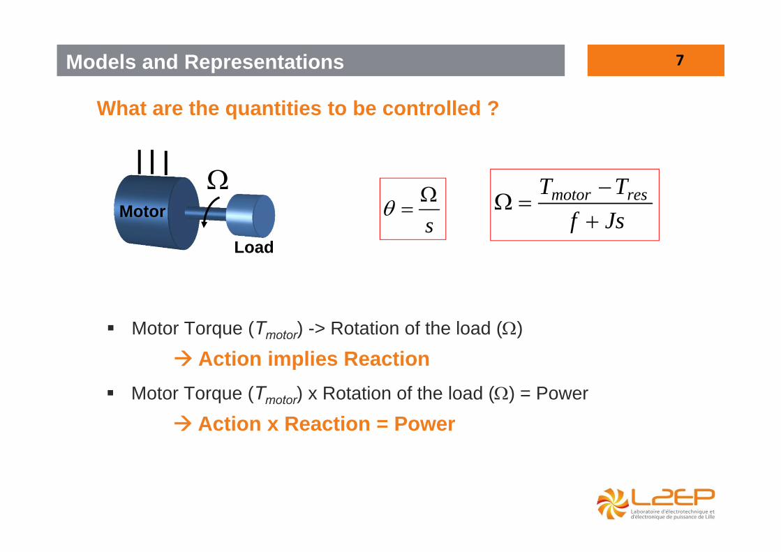
What are the quantities to be controlled ?
Motor Torque (Tmotor) -> Rotation of the load ()
Action implies Reaction
Motor
Load
s
Motor Torque (Tmotor) x Rotation of the load () = Power
Action x Reaction = Power
JsfTT resmotor

8
resout Tp
motorin Tp
Energetic Macroscopic Representation makes possible to represent a model in order to:• To respect the natural (integral) causality • To highlight actions and reactions and power flows
Motor
Load
Motor Env
*motorT
motorT
resT
""storedlossesoutin pppp
)1(s
)2(JsfTT resmotor
1
2
Losses + storage
Source
Source
Models and Representations

9Modelling and EMR of a PMSM
Constitution of a PMSM- Stator composed of three windings- Rotor composed of surface mounted or buried magnets
10
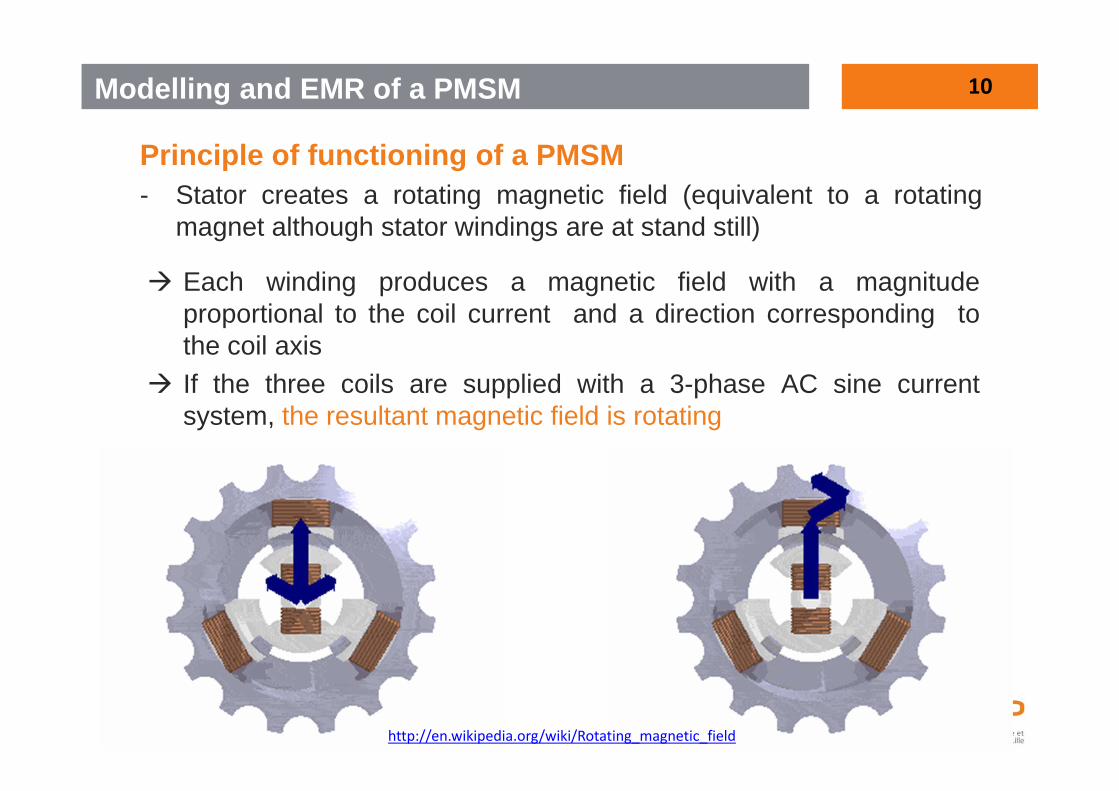
Principle of functioning of a PMSM- Stator creates a rotating magnetic field (equivalent to a rotating
magnet although stator windings are at stand still)
Modelling and EMR of a PMSM
Each winding produces a magnetic field with a magnitudeproportional to the coil current and a direction corresponding tothe coil axis
If the three coils are supplied with a 3-phase AC sine currentsystem, the resultant magnetic field is rotating
http://en.wikipedia.org/wiki/Rotating_magnetic_field

11
Principle of functioning of a PMSM- Stator creates a rotating magnetic field (equivalent to a rotating
magnet although stator windings are at stand still)- Rotor magnets are attracted by the rotating field and rotate at the
same speed (in steady state)
Bss
Brr
+ C
N
S
ssrr BBkC
Torque Control requires a VECTOR CONTROL
Modelling and EMR of a PMSM
12
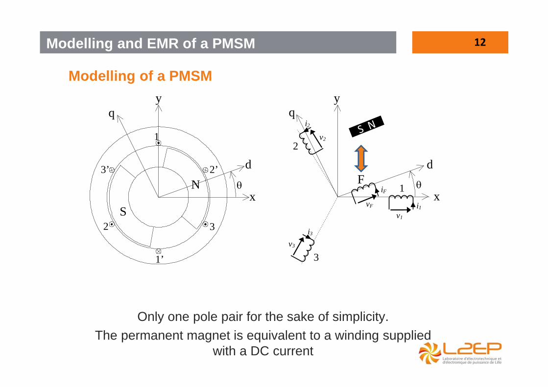
Modelling of a PMSM
d 3’
2 3
1
2’
x
d
q
N
S
1
q
2
3
y
1’
F
v1
i1 vF
iF
i2
v2
i3
v3
y
x
Only one pole pair for the sake of simplicity.The permanent magnet is equivalent to a winding supplied
with a DC current
Modelling and EMR of a PMSM

13
Modelling of a PMSM
r
r
r
s
s
s
3
2
1
3
2
1
3
2
1
Stator flux linkage equations are
with
3
2
1
3
2
1
iii
LMMMLMMML
sss
sss
sss
s
s
s
and
3/4cos3/2cos
cos
max
3
2
1
r
r
r
Modelling and EMR of a PMSM
FF iMmax in case of wound-rotor
cstemax in case of rotor with permanent magnets
14
Modelling of a PMSM
r
r
r
s
s
s
ss dtd
dtd
iii
Rdtd
iii
Rvvv
3
2
1
3
2
1
3
2
1
3
2
1
3
2
1
3
2
1
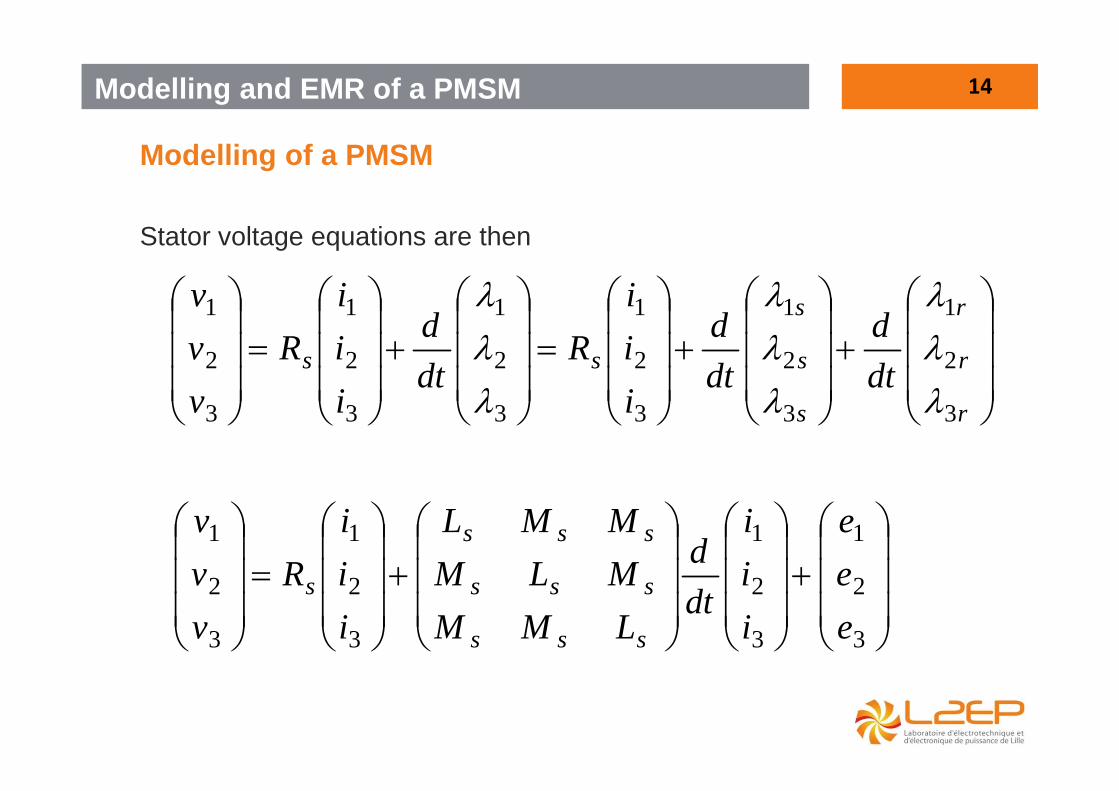
Stator voltage equations are then
3
2
1
3
2
1
3
2
1
3
2
1
eee
iii
dtd
LMMMLMMML
iii
Rvvv
sss
sss
sss
s
Modelling and EMR of a PMSM

15
Modelling of a PMSM
Or in a more concise way (matrix notation)
edt
idLiRv ss
with
3
2
1
vvv
v
3
2
1
iii
i
Voltage vector
Current vector
3
2
1
eee
e EMF vector
sR Stator resistance
sL Stator inductance matrix
Modelling and EMR of a PMSM

16
Modelling of a PMSM
emmaglossesin pppp The power balance is
With
332211. ivivivivp tin
iLi
dtdi
dtidLp st
tsmag .
21
23
22
21
2. iRiRiRiRp sssslosses
Modelling and EMR of a PMSM

17
Modelling of a PMSM
and
emtem Tieieieiep 332211
then
332211 ieieieiepT tem
em
As
dd
dd
dtd
dtde rrr
then id
dT tr
em
Torque Control requires a VECTOR CONTROL
Modelling and EMR of a PMSM

18
Modelling of a PMSM
If
3/4cos3/2cos
cos
max
3
2
1
r
r
r
3/4sin3/2sin
sin
max
3
2
1
3
2
1
r
r
r
dd
eee
and
then
3/4sin3/2sinsin 321max iiiTem
Modelling and EMR of a PMSM

19
Modelling of a PMSM
Question: Find the current references that lead to a constant torque under minimum copper losses
Modelling and EMR of a PMSM

20
Modelling of a PMSM
Solution:
d
dTd
d
ddTi remr
r
em
2max
*
2
**
23
2. iRp slosses is minimum if is minimum iFor a given , *
emT is minimum if is collinear to i
ddkii r*
i
dd r
i.e.
Then 2
*
ddk
ddk
dd
T rrtrem
Modelling and EMR of a PMSM
21
Modelling of a PMSM
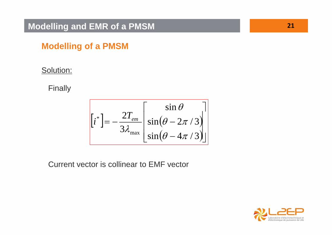
Solution:
3/4sin3/2sin
sin
32
max
*
emTi
Finally
Current vector is collinear to EMF vector
Modelling and EMR of a PMSM

22
Modelling of a PMSM
If the stator windings are star coupled:
13u
23u
1v
2v 3v
Only two voltages and two currents are sufficient to model the machine:
2i
1i
3i
0321 iii
3
2
1
3
2
1
3
2
1
3
2
1
eee
iii
dtd
LMMMLMMML
iii
Rvvv
sss
sss
sss
s
Question: Rewrite the voltage equation withas variables
231321 ,,, uuii
Modelling and EMR of a PMSM

23
Modelling of a PMSM
Solution:
32
31
2
1
2
1
32
31
23
13
2112
2112
eeee
ii
dtdL
ii
Rvvvv
uu
cs
ssc MLL is called the stator cyclic inductance
Remark: if we add the same quantity vZ (Zero-sequence) to v1, v2and v3, u13 and u23 remain the same.
Modelling and EMR of a PMSM
24
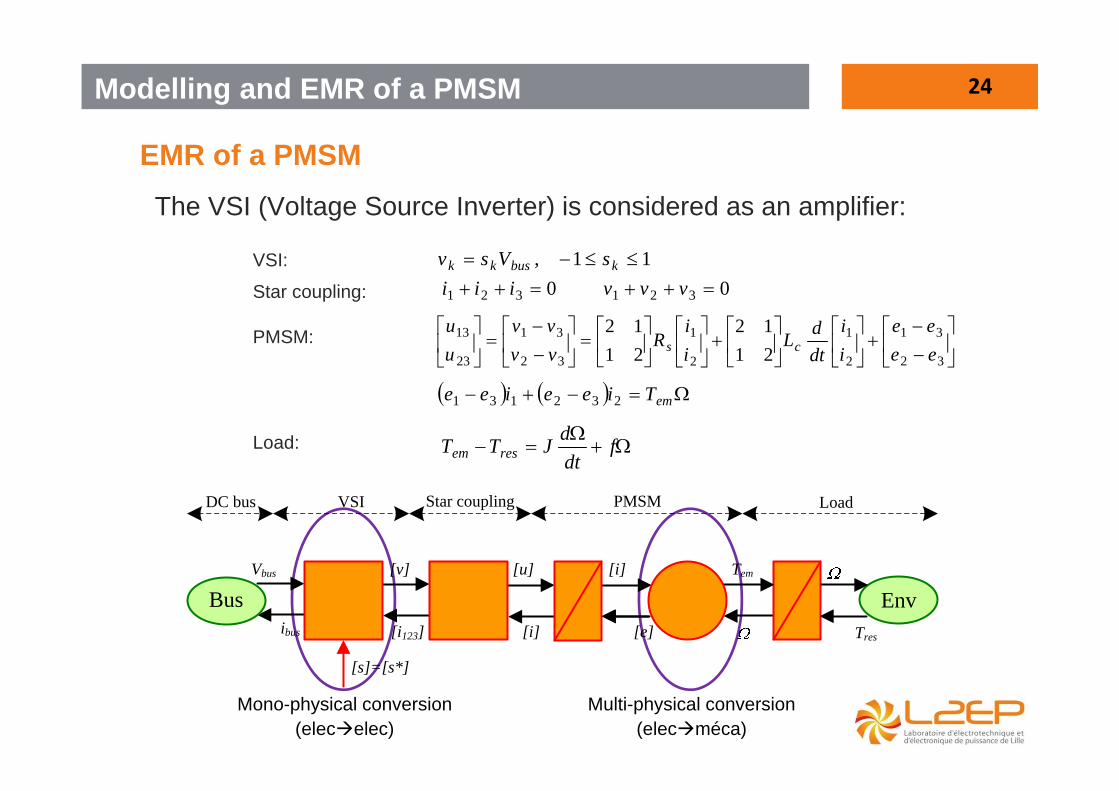
EMR of a PMSMThe VSI (Voltage Source Inverter) is considered as an amplifier:
Mono-physical conversion (elecelec)
Multi-physical conversion (elecméca)
Modelling and EMR of a PMSM
11, kbuskk sVsv
32
31
2
1
2
1
32
31
23
13
2112
2112
eeee
ii
dtdL
ii
Rvvvv
uu
cs
emTieeiee 232131
fdtdJTT resem
0321 vvv0321 iii
Bus Env
DC bus VSI Star coupling LoadPMSM
Vbus
ibus
[s]=[s*]
[v]
[i123]
[u]
[i]
[i]
[e]
Tem
Tres
VSI:
Star coupling:
PMSM:
Load:

25
From EMR to Simulink…
Modelling and EMR of a PMSM
VSI Star coupling PMSM+Loadf+J
PMSMR+L
PMSMEM conversion
Load
Env
DC Source
Bus Vbus [v ] [u]
[i123]ibus
[i]
[i]
Tem Omega Tres
Omega[e]
[s*]

26Principles of Inversion Based Control
(.)input output
u(t) y(t)
-1(.)desiredoutput
Controlling a system for output tracking can be interpreted as inverting the system
yref(t) Control
… if we can implement a good approximation of the system’s inverse
System
uref(t)
inputreference
Open loop and closed-loop controls

27
Open loop controls
v(t)
-1(.)
Let’s take a simple example: current control of a resistance
Control
System
)(~)(:.~ **1 tiRtv
R1:.
*v R
i(t)i
v*(t) i*(t)Con
trol
syst
em
*iv
In case of acausal relationship (no accumulation), open loop control is possible (No need of controllers).The inversion of the element is said “direct”.
Principles of Inversion Based Control

28
Open loop controls
Principles of Inversion Based Control
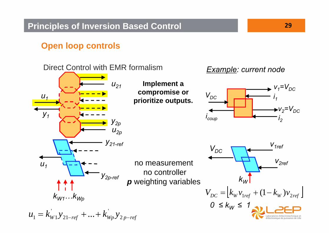
Direct Control with EMR formalism
y2
u2
Objective: to control y2
u1
y1
y2 = f(u1 )+g(u2 )
Compensate u2Manipulate u1
y2*u1*u1*=f-1(y2* )+g(u2 )~
u1
y1 k
y2 = k x u1y2
u2
y1 = (1/k)x u2
y2*u1~
k*
k* = y2 */u1~
29
Open loop controls
Principles of Inversion Based Control
Direct Control with EMR formalism
u1
y1
u21
no measurement no controller
p weighting variables
y2pu2p
u1
y2p-ref
y21-ref
kW1…kWp
refpWprefW ykyku 2'
21'
11 ...
Implement a compromise or
prioritize outputs.
VDC
v1=VDC
i2v2=VDC
i1VDC
icoup
refWrefWDC vkvkV 21 )1(
v1ref
kW
v2ref
Example: current node
0 ≤ kW ≤ 1

30
Closed-loop controls
Principles of Inversion Based Control
v(t)
-1(.)
Let’s take a simple example: current control of a R+L circuit
Control
System LsR
1:.
*vR
i(t)i
v*(t) i*(t)Con
trol
syst
em
*iv
In case of causal relationship (accumulation of energy), open loop control is not possible Need of controllers
L
)(~~)(:.~ **1 sisLRsv No derivative in real-time

31
Closed-loop controls
Principles of Inversion Based Control
v(t)
Controller
Let’s take a simple example: current control of a R+L circuit
Control
System*v
Ri(t)
i
v*(t)i*(t)
Con
trol
syst
em
*iv
In case of causal relationship (accumulation of energy), closed-loop control is mandatory
Need of measurements and controllers (Indirect control)
L
)()()(: ** sisisCsvController
LsR
1:.
32
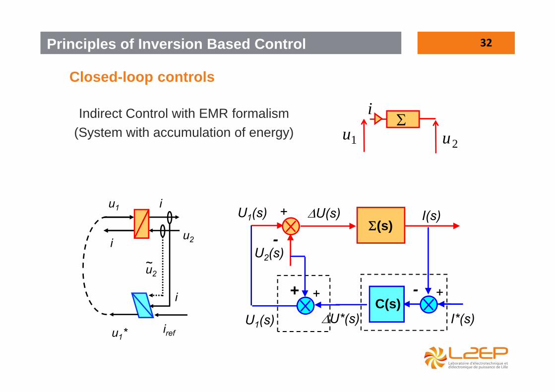
Closed-loop controls
Principles of Inversion Based Control
u2
i
i
u1
Indirect Control with EMR formalism(System with accumulation of energy)
U2(s)
U1(s)
-
+(s)
U(s) I(s)
+
U1(s)
+I*(s)U*(s)
C(s)+-
iref
u2
i
u1*
~
1u
2u
i
33
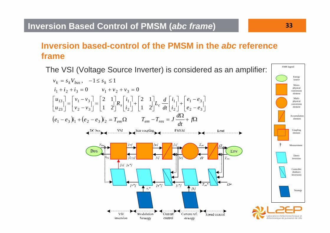
Inversion based-control of the PMSM in the abc reference frame
Inversion Based Control of PMSM (abc frame)
emTieeiee 232131
32
31
2
1
2
1
32
31
23
13
2112
2112
eeee
ii
dtdL
ii
Rvvvv
uu
cs
The VSI (Voltage Source Inverter) is considered as an amplifier:
fdtdJTT resem
11, kbuskk sVsv0321 vvv0321 iii
Energysource
Mono-physical
conversionelement
Accumulationelement
Couplingelement
Direct inversion
Controller(Indirect
Inversion)
Strategy
EMR legend
Measurement
Multi-physical
conversionelement
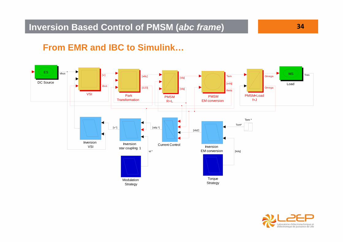
34
From EMR and IBC to Simulink…
Inversion Based Control of PMSM (abc frame)
VSI
TorqueStrategy
Tem *
ParkTransformation
PMSM+Loadf+J
PMSM R+L
PMSMEM conversion
ModulationStrategy
Load
MS
Inversionstar coupling 1
InversionVSI Inversion
EM conversion
DC Source
ES
Current Control
Vbus [v ] [vdq ]
[i123]ibus
[idq]
[idq]
Tem Omega Tres
[edq]
thetaOmega
[vdq *]
vz *
[v *][idq*]
[kdq]
Tem*
35
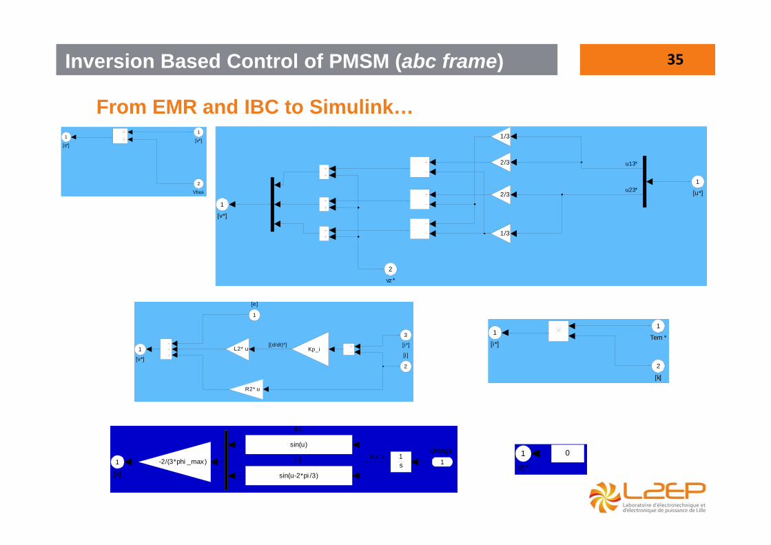
From EMR and IBC to Simulink…
Inversion Based Control of PMSM (abc frame)
[s*]
1
Vbus
2
[v*]
1
[v*]
1
R2* u
L2* u Kp_i[i*]
3
[i]
2
[e]
1
[(d/dt)*] [i*]
1
[k]
2
Tem *
1
[v*]
12/3
2/3
1/3
1/3
vz*
2
[u*]
1
u13*
u23*
vz*
1 0
[k]
1 e2
sin(u-2*pi /3)
e1
sin(u)
1s-2/(3*phi _max)
Omega
1theta
36
From EMR and IBC to Simulink…
Inversion Based Control of PMSM (abc frame)
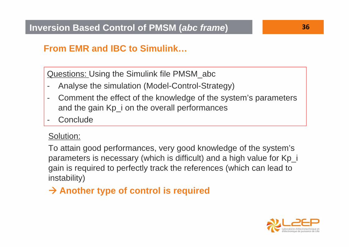
Questions: Using the Simulink file PMSM_abc- Analyse the simulation (Model-Control-Strategy)- Comment the effect of the knowledge of the system’s parameters
and the gain Kp_i on the overall performances- Conclude
Solution:To attain good performances, very good knowledge of the system’s parameters is necessary (which is difficult) and a high value for Kp_igain is required to perfectly track the references (which can lead to instability) Another type of control is required
37
Modelling of a PMSM in the dq reference frame
Inversion Based Control of PMSM (dq frame)
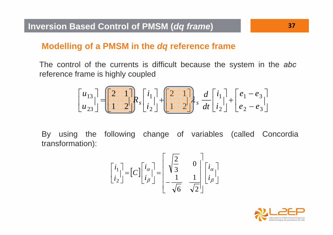
The control of the currents is difficult because the system in the abcreference frame is highly coupled
32
31
2
1
2
1
23
13
2112
2112
eeee
ii
dtd
ii
Ruu
ss
By using the following change of variables (called Concordiatransformation):
ii
ii
Cii
21
61
032
2
1

38
Modelling of a PMSM in the dq reference frame
Inversion Based Control of PMSM (dq frame)
The system becomes :
32
31
23
13
2112
2112
eeee
Cii
dtdLCC
ii
CRCuu
C tc
ts
tt
Considering:
23
13
uu
Cvv t
23
13
ee
Cee t
It comes:
ee
ii
dtd
LL
ii
RR
vv
c
c
s
s
00
00
The real three phase machine is equivalent to a fictitious twoindependent phase machine (All matrices are diagonal).
39
Modelling of a PMSM in the dq reference frame
Inversion Based Control of PMSM (dq frame)
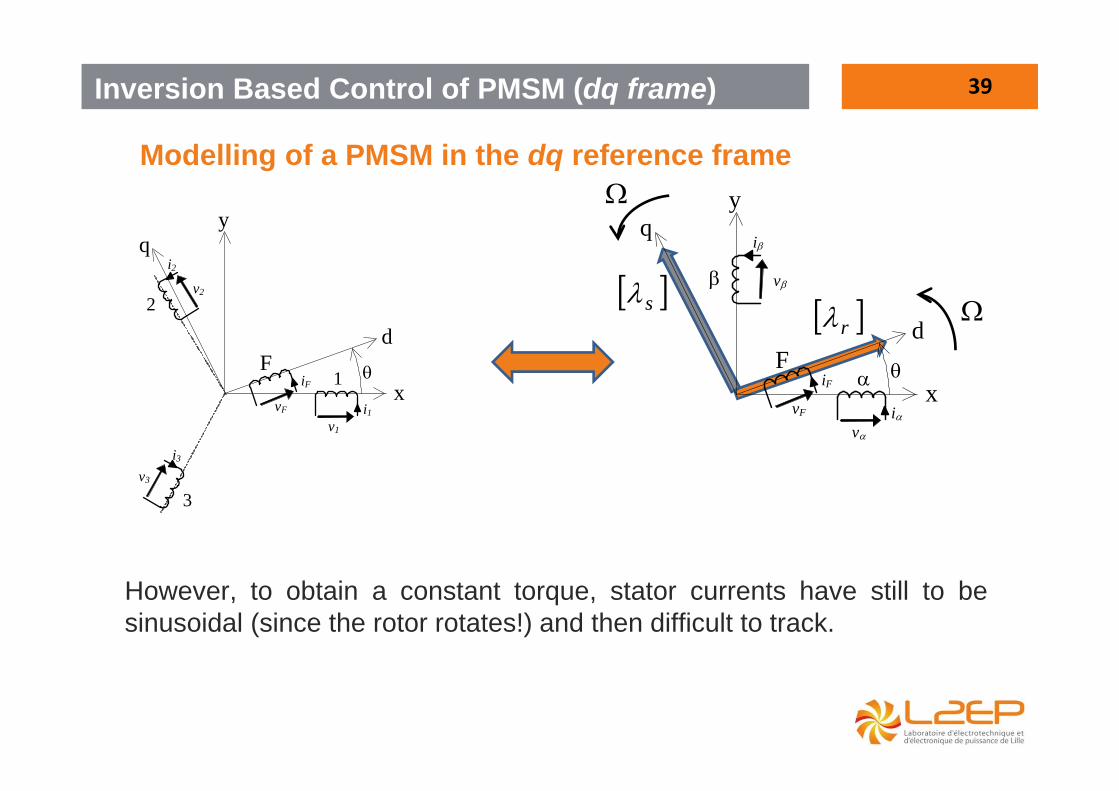
However, to obtain a constant torque, stator currents have still to besinusoidal (since the rotor rotates!) and then difficult to track.
d
1
q
2
3
y
F
v1
i1 vF
iF
i2
v2
i3
v3
x
d
q
y
F
v
i vF
iF
i
v
x
s r
40
Modelling of a PMSM in the dq reference frame
Inversion Based Control of PMSM (dq frame)
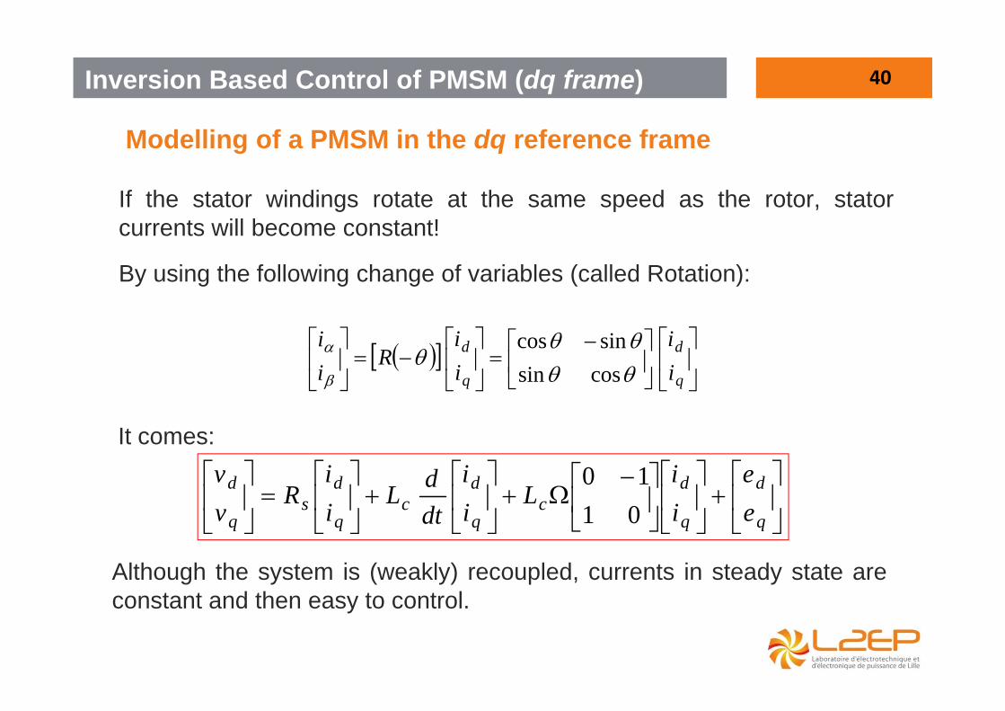
If the stator windings rotate at the same speed as the rotor, statorcurrents will become constant!
By using the following change of variables (called Rotation):
q
d
q
d
ii
ii
Rii
cossinsincos
It comes:
q
d
q
dc
q
dc
q
ds
q
d
ee
ii
Lii
dtdL
ii
Rvv
0110
Although the system is (weakly) recoupled, currents in steady state areconstant and then easy to control.
41
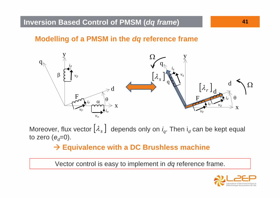
Modelling of a PMSM in the dq reference frame
Inversion Based Control of PMSM (dq frame)
d
q
y
F
v
i vF
iF
i
v
x
d
q
q
y
F
vF
iF
iq
vq
x
d id
vd
s r
Moreover, flux vector depends only on iq. Then id can be kept equalto zero (ed=0).
Equivalence with a DC Brushless machine
s
Vector control is easy to implement in dq reference frame.
42
d
q
y
F
v
i vF
iF
i
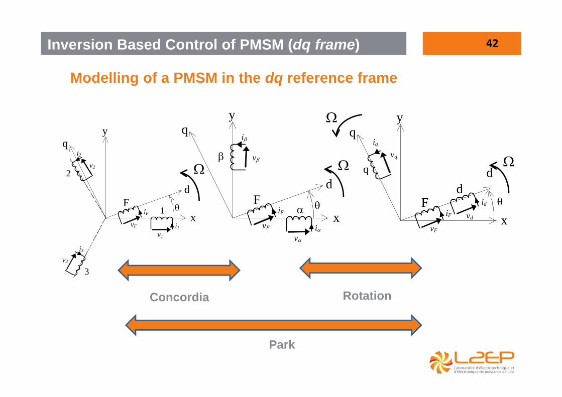
v
x
Modelling of a PMSM in the dq reference frame
Inversion Based Control of PMSM (dq frame)
Concordia Rotation
Park
d
q
q
y
F
vF
iF
iq
vq
x
d id
vd
d
1
q
2
3
y
F
v1
i1 vF
iF
i2
v2
i3
v3
x
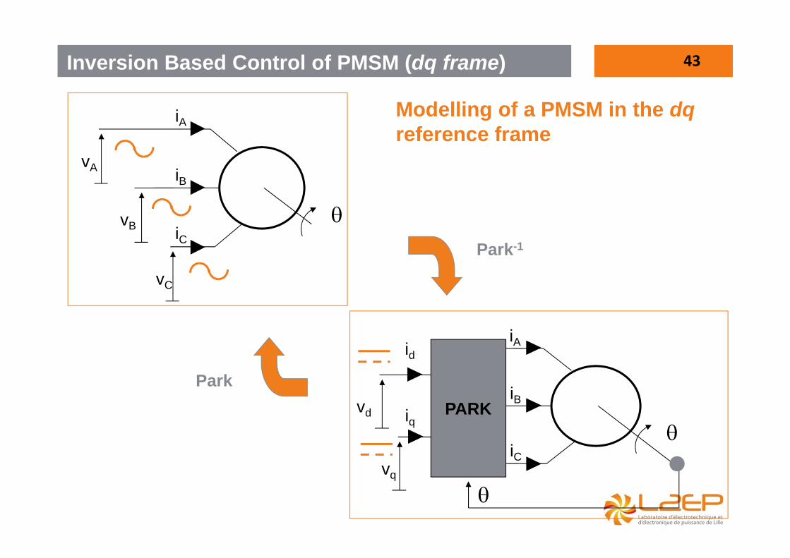
43
Modelling of a PMSM in the dqreference frame
Inversion Based Control of PMSM (dq frame)
vA
vB
vC
iA
iB
iC
vd
vq
PARK
iq
iA
iB
iC
id
Park-1
Park
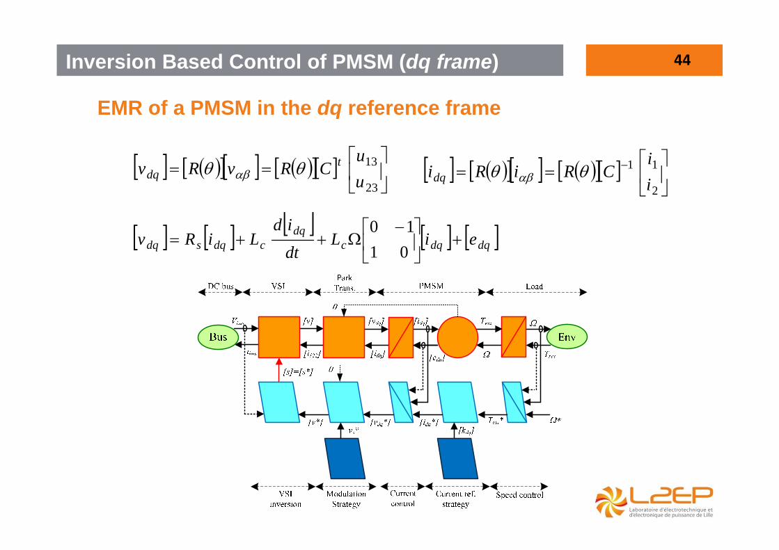
44
EMR of a PMSM in the dq reference frame
Inversion Based Control of PMSM (dq frame)
dqdqcdq
cdqsdq eiLdtid
LiRv
0110
23
13
uu
CRvRv tdq
2
11
ii
CRiRidq

45Inversion Based Control of PMSM (dq frame)
Questions: Using the Simulink file PMSM_dq_students- Simulate the control system using the EMR- Conclude
From EMR and IBC to Simulink…

46References[1] “Control Strategies for Open-End Winding Drives Operating in the Flux-Weakening Region”. IEEETransactions on Power Electronics, 9-2013, Alexandru-Paul SANDULESCU, Fabien MEINGUET, XavierKESTELYN, Eric SEMAIL, Antoine BRUYERE[2] “Model-based decoupling control method for dual-drive gantry stages: A case study with experimentalvalidations”. Control Engineering Practice, Vol. 21, N°. 3, pages. pp. 298-307, 3-2013, Ivan MauricioGARCIAHERREROS, Xavier KESTELYN, Julien GOMAND, Ralph COLEMAN, Pierre-Jean BARRE[3] “A Vectorial Approach for Generation of Optimal Current References for Multiphase PermanentMagnet Synchronous Machines in Real-time”. IEEE Transactions on Industrial Electronics, Vol. 58, N°.11, pages. 5057 - 5065, ISBN0278-00462-2011, Xavier KESTELYN, Eric SEMAIL[4] “Control of a Symmetrical Dual-drive Gantry System using Energetic Macroscopic Representation”.Solid State Phenomena (SSP), Vol. 144, pages. 181-185, ISBN3-908451-60-42-2009, XavierKESTELYN, Julien GOMAND, Alain BOUSCAYROL, Pierre-Jean BARRE[5] “FPGA Implementation of a General Space Vector Approach on a 6-Leg Voltage Source Inverter”.IECON 2011 - IEEE International Conference On Industrial Applications of Electronics, N°. 37, pages.3482-3487, ISBN978-1-61284-969-09-2011, Alexandru-Paul SANDULESCU, Lahoucine IDKHAJINE,Sebastien CENSE, Frédéric COLAS, Xavier KESTELYN, Eric SEMAIL, Antoine BRUYERE[6] “Teaching drive control using Energetic Macroscopic Representation - expert level”. EPE’09,Barcelona, Spain, 7-2009. Alain BOUSCAYROL, Philippe DELARUE, Frédéric GIRAUD, XavierGUILLAUD, Xavier KESTELYN, Betty LEMAIRE-SEMAIL, Walter LHOMME[7] “Vectorial Modeling and Control of Multiphase Machines with Non-salient Poles Supplied by anInverter”. Chapter 5 of "Control of Non-conventional Synchronous Motors. ISTE Ltd and John Wiley &Sons Inc, pages. 448-470, ISBN978-1-84821-331-912-2011, Xavier KESTELYN, Eric SEMAIL[8] “Multiphase Voltage source Inverters”. Chapter 8 of "Power electronic Converters - PWM Strategiesand current control techniques". ISTE Ltd and John Wiley & Sons Inc ., pages. 203-242, ISBN978-1-84821-195-73-2011, Xavier KESTELYN, Eric SEMAIL

Thanks for your attention


