14
Introduction to Introduction to VHDL VHDL CLASS MATERIALS CLASS MATERIALS EECE 255 EECE 255
| Date post: | 01-Jan-2016 |
| Category: |
Documents |
| Upload: | vernon-vance |
| View: | 81 times |
| Download: | 0 times |
Introduction to Introduction to VHDLVHDLIntroduction to Introduction to VHDLVHDL
CLASS MATERIALSCLASS MATERIALS
EECE 255EECE 255
Very High Speed Integrated Circuit
Hardware Description Language • Industry standard language to describe hardware
• Originated from work in 70’s & 80’s by the U.S. Department of Defence
• Root : ADA Language
► a structured, statically typed, imperative and
object-oriented high-level computer programming
language based on Pascal
• In 1986, VHDL was proposed as an IEEE standard, and
in 1987, it was adopted as the IEEE 1076 standard
VHDL Format : Library (1)
• Library files have commonly used packages and entities in your design. A VHDL package file contains common design elements that you can use in the VHDL file source files that make up design.
• IEEE created the IEEE VHDL library and std_logic type in standard 1164.
• Parts of the IEEE library can be included in an entity by inserting lines like these before your entity declaration
Ex. library ieee;
use ieee.std_logic_1164.all; most case
use ieee.std_logic_arith.all;
VHDL Format : Library (2)
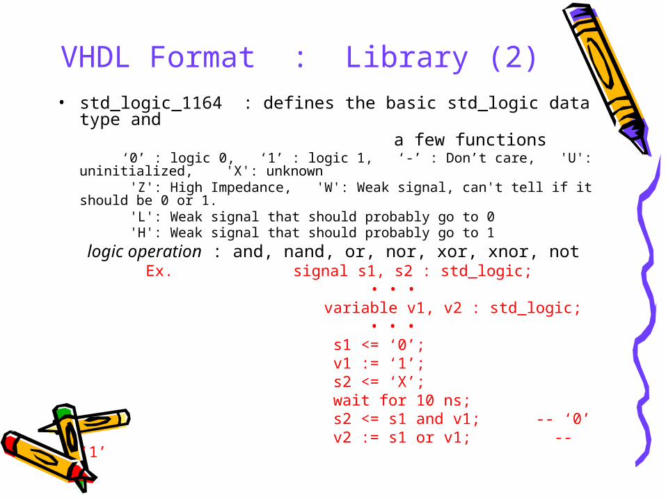
• std_logic_1164 : defines the basic std_logic data type and a few functions ‘0’ : logic 0, ‘1’ : logic 1, ‘-’ : Don’t care, 'U': uninitialized, 'X': unknown 'Z': High Impedance, 'W': Weak signal, can't tell if it should be 0 or 1. 'L': Weak signal that should probably go to 0 'H': Weak signal that should probably go to 1
logic operation : and, nand, or, nor, xor, xnor, not Ex. signal s1, s2 : std_logic; • • • variable v1, v2 : std_logic; • • • s1 <= ‘0’; v1 := ‘1’; s2 <= ‘X’; wait for 10 ns; s2 <= s1 and v1; -- ‘0’ v2 := s1 or v1; -- ‘1’
VHDL Format : Library (3)
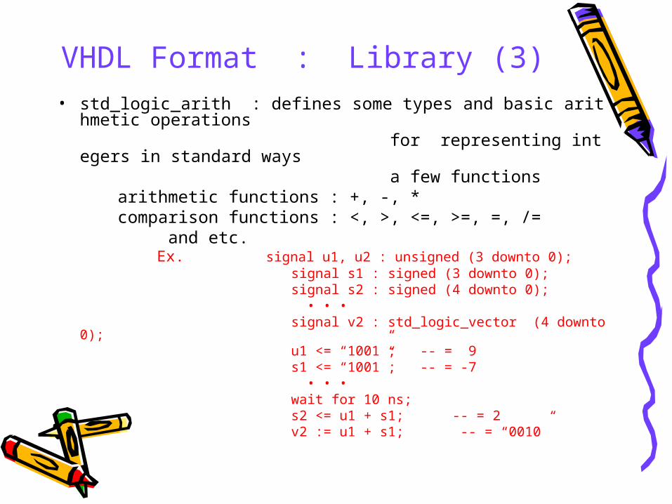
• std_logic_arith : defines some types and basic arithmetic operations for representing integers in standard ways a few functions arithmetic functions : +, -, * comparison functions : <, >, <=, >=, =, /= and etc. Ex. signal u1, u2 : unsigned (3 downto 0); signal s1 : signed (3 downto 0); signal s2 : signed (4 downto 0); • • • signal v2 : std_logic_vector (4 downto 0); u1 <= “1001”; -- = 9 s1 <= “1001”; -- = -7 • • • wait for 10 ns; s2 <= u1 + s1; -- = 2 v2 := u1 + s1; -- = “0010”
VHDL Format : Library (4)
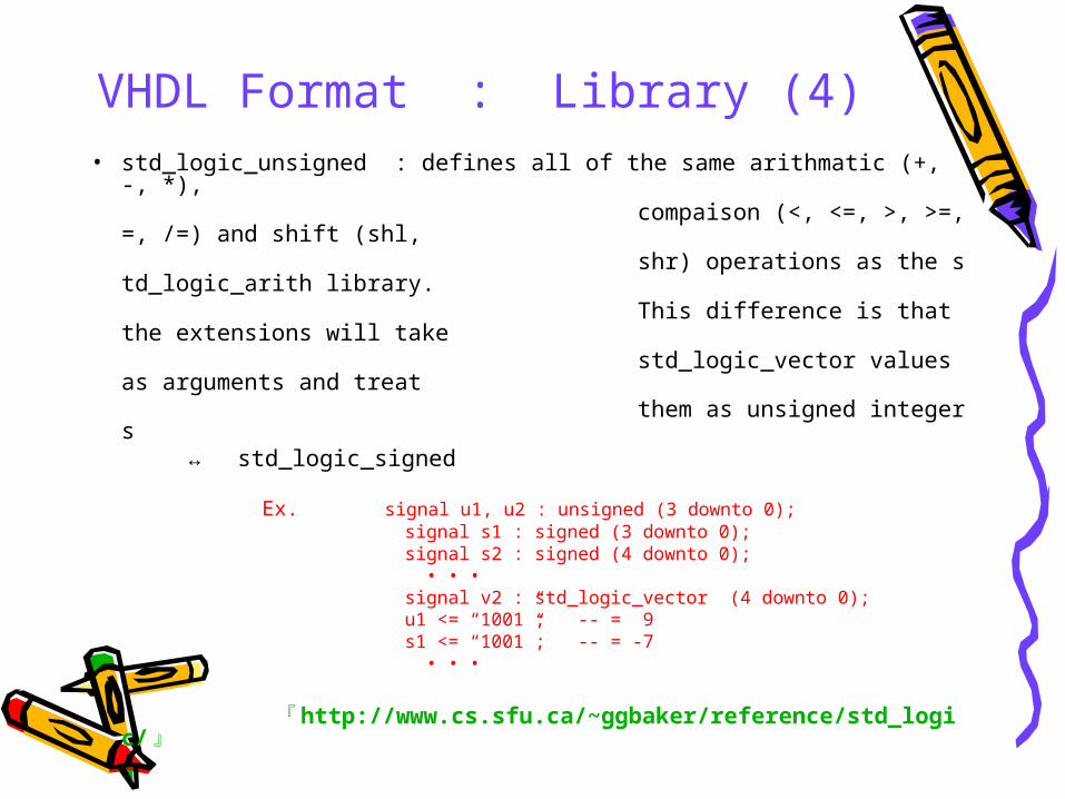
• std_logic_unsigned : defines all of the same arithmatic (+, -, *), compaison (<, <=, >, >=, =, /=) and shift (shl, shr) operations as the std_logic_arith library. This difference is that the extensions will take std_logic_vector values as arguments and treat
them as unsigned integers ↔ std_logic_signed Ex. signal u1, u2 : unsigned (3 downto 0); signal s1 : signed (3 downto 0); signal s2 : signed (4 downto 0); • • • signal v2 : std_logic_vector (4 downto 0); u1 <= “1001”; -- = 9 s1 <= “1001”; -- = -7 • • •
『 http://www.cs.sfu.ca/~ggbaker/reference/std_logic/ 』
VHDL Format : Entity (1)
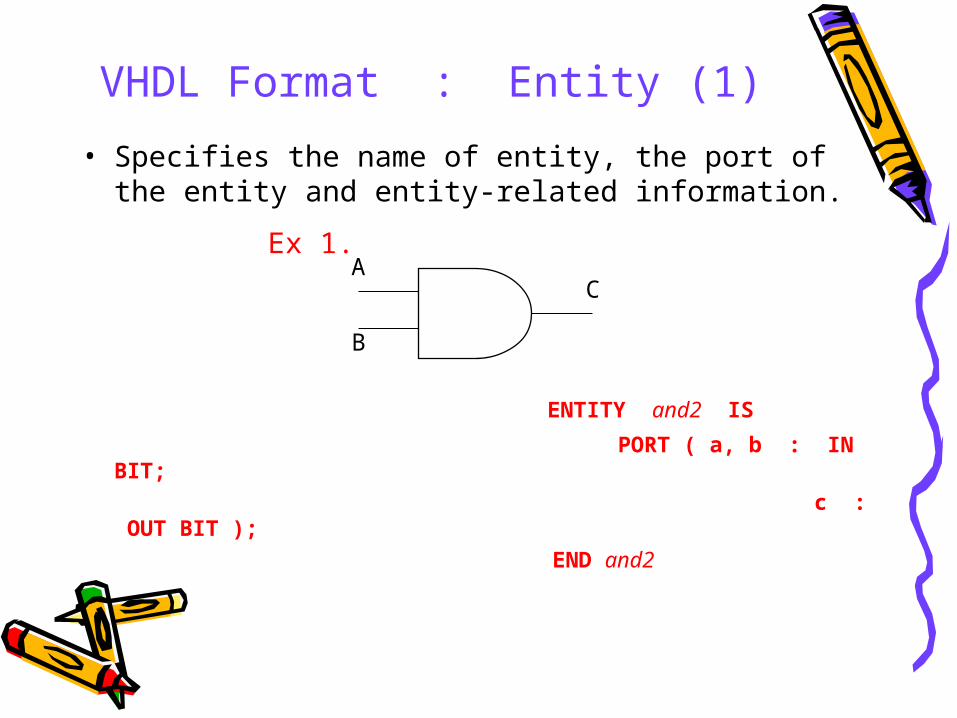
• Specifies the name of entity, the port of the entity and entity-related information.
Ex 1.
ENTITY and2 IS
PORT ( a, b : IN BIT;
c : OUT BIT );
END and2
A
B
C
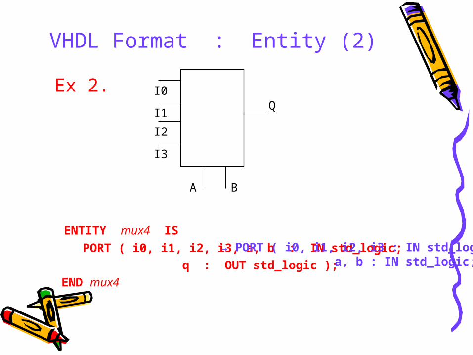
VHDL Format : Entity (2)
Ex 2.
ENTITY mux4 IS
PORT ( i0, i1, i2, i3, a, b : IN std_logic;
q : OUT std_logic );
END mux4
I0
I1
I2
I3
A B
Q
→ PORT ( i0, i1, i2, i3 : IN std_logic; a, b : IN std_logic;
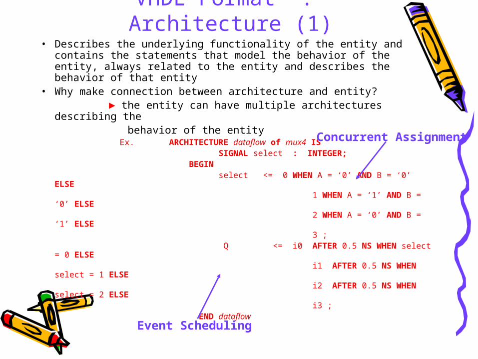
VHDL Format : Architecture (1)• Describes the underlying functionality of the entity and contains the
statements that model the behavior of the entity, always related to the entity and describes the behavior of that entity
• Why make connection between architecture and entity? ► the entity can have multiple architectures describing the behavior of the entity Ex. ARCHITECTURE dataflow of mux4 IS SIGNAL select : INTEGER; BEGIN select <= 0 WHEN A = ‘0’ AND B = ‘0’ ELSE 1 WHEN A = ‘1’ AND B = ‘0’ ELSE 2 WHEN A = ‘0’ AND B = ‘1’ ELSE 3 ; Q <= i0 AFTER 0.5 NS WHEN select = 0 ELSE i1 AFTER 0.5 NS WHEN select = 1 ELSE i2 AFTER 0.5 NS WHEN select = 2 ELSE i3 ; END dataflow
Concurrent Assignment
Event Scheduling
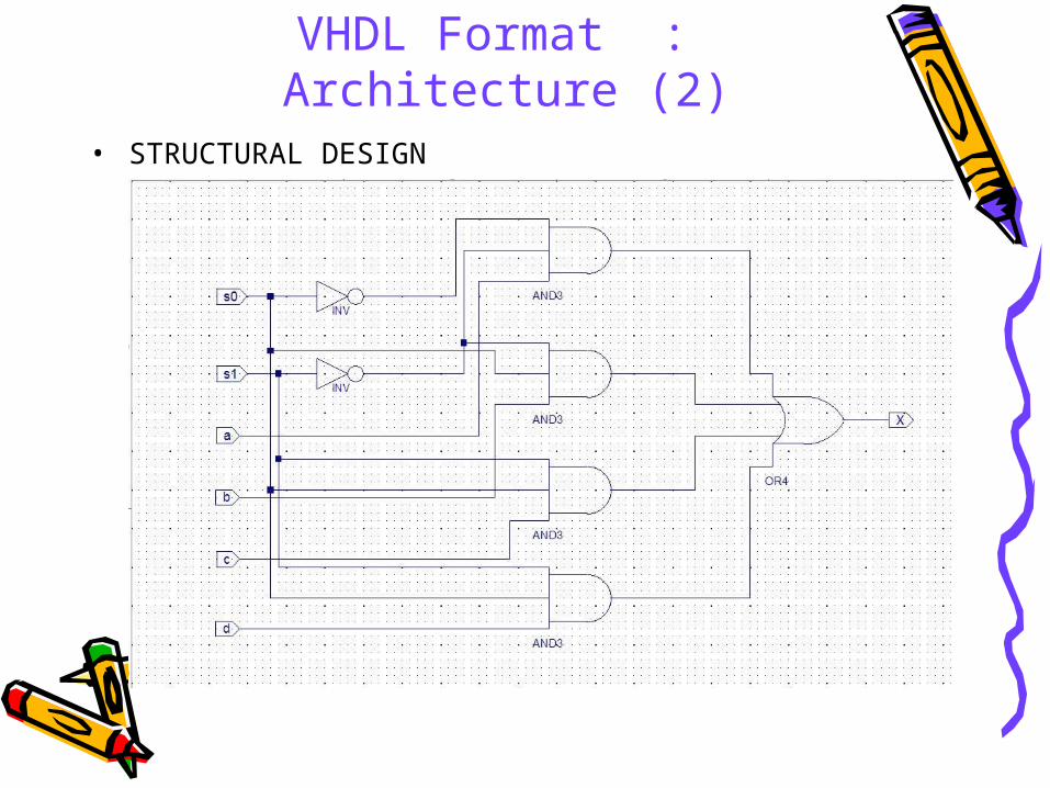
VHDL Format : Architecture (2)• STRUCTURAL DESIGN
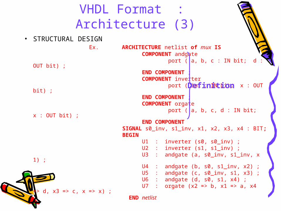
VHDL Format : Architecture (3)• STRUCTURAL DESIGN Ex. ARCHITECTURE netlist of mux IS COMPONENT andgate port ( a, b, c : IN bit; d : OUT bit) ; END COMPONENT ; COMPONENT inverter port ( in1 : IN bit; x : OUT bit) ; END COMPONENT ; COMPONENT orgate port ( a, b, c, d : IN bit; x : OUT bit) ; END COMPONENT SIGNAL s0_inv, s1_inv, x1, x2, x3, x4 : BIT; BEGIN U1 : inverter (s0, s0_inv) ; U2 : inverter (s1, s1_inv) ; U3 : andgate (a, s0_inv, s1_inv, x1) ; U4 : andgate (b, s0, s1_inv, x2) ; U5 : andgate (c, s0_inv, s1, x3) ; U6 : andgate (d, s0, s1, x4) ; U7 : orgate (x2 => b, x1 => a, x4 => d, x3 => c, x => x) ; END netlist
Definition
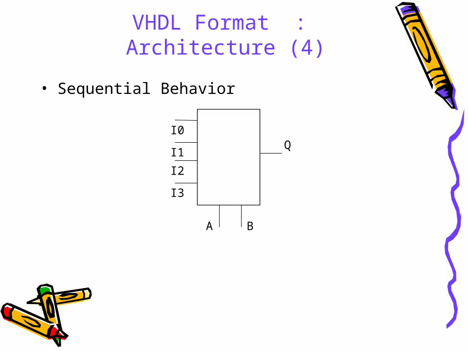
VHDL Format : Architecture (4)
• Sequential Behavior
I0
I1
I2
I3
A B
Q
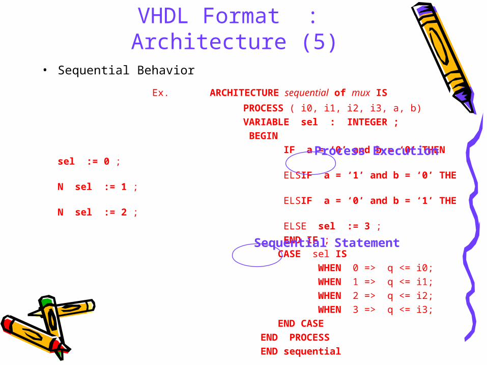
VHDL Format : Architecture (5)• Sequential Behavior
Ex. ARCHITECTURE sequential of mux IS
PROCESS ( i0, i1, i2, i3, a, b)
VARIABLE sel : INTEGER ;
BEGIN
IF a = ‘0’ and b = ‘0’ THEN sel := 0 ;
ELSIF a = ‘1’ and b = ‘0’ THEN sel := 1 ;
ELSIF a = ‘0’ and b = ‘1’ THEN sel := 2 ;
ELSE sel := 3 ;
END IF ;
CASE sel IS
WHEN 0 => q <= i0;
WHEN 1 => q <= i1;
WHEN 2 => q <= i2;
WHEN 3 => q <= i3;
END CASE
END PROCESS
END sequential
Process Execution
Sequential Statement