36
Introduction to Wireless Networking 802.11 Medium Access Module-06 Jerry Bernardini Community College of Rhode Island 03/15/22 Wireless Networking J. Bernardini 1
| Date post: | 16-Dec-2015 |
| Category: |
Documents |
| Upload: | randall-hunter |
| View: | 220 times |
| Download: | 1 times |
Introduction to Wireless Networking
802.11 Medium AccessModule-06
Jerry BernardiniCommunity College of Rhode Island
04/18/23 Wireless Networking J. Bernardini 1
Presentation Reference Material• CWNA Certified Wireless Network
Administration Official Study Guide (PWO-104), David Coleman, David Westcott,
2009, Chapter-8
04/18/23 Wireless Networking J. Bernardini 2
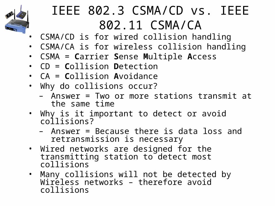
IEEE 802.3 CSMA/CD vs. IEEE 802.11 CSMA/CA• CSMA/CD is for wired collision handling• CSMA/CA is for wireless collision handling• CSMA = Carrier Sense Multiple Access• CD = Collision Detection• CA = Collision Avoidance• Why do collisions occur?
– Answer = Two or more stations transmit at the same time
• Why is it important to detect or avoid collisions?– Answer = Because there is data loss and retransmission
is necessary• Wired networks are designed for the transmitting station to
detect most collisions• Many collisions will not be detected by Wireless networks –
therefore avoid collisions
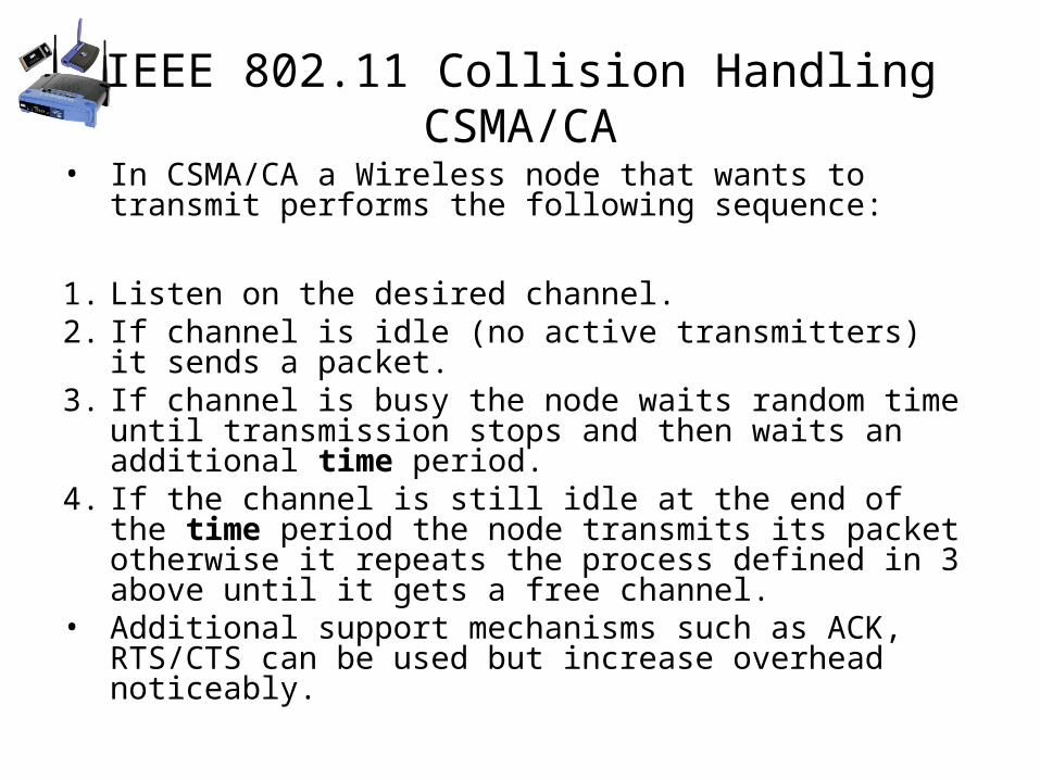
IEEE 802.11 Collision Handling CSMA/CA
• In CSMA/CA a Wireless node that wants to transmit performs the following sequence:
1. Listen on the desired channel. 2. If channel is idle (no active transmitters) it sends a packet. 3. If channel is busy the node waits random time until
transmission stops and then waits an additional time period. 4. If the channel is still idle at the end of the time period the
node transmits its packet otherwise it repeats the process defined in 3 above until it gets a free channel.
• Additional support mechanisms such as ACK, RTS/CTS can be used but increase overhead noticeably.
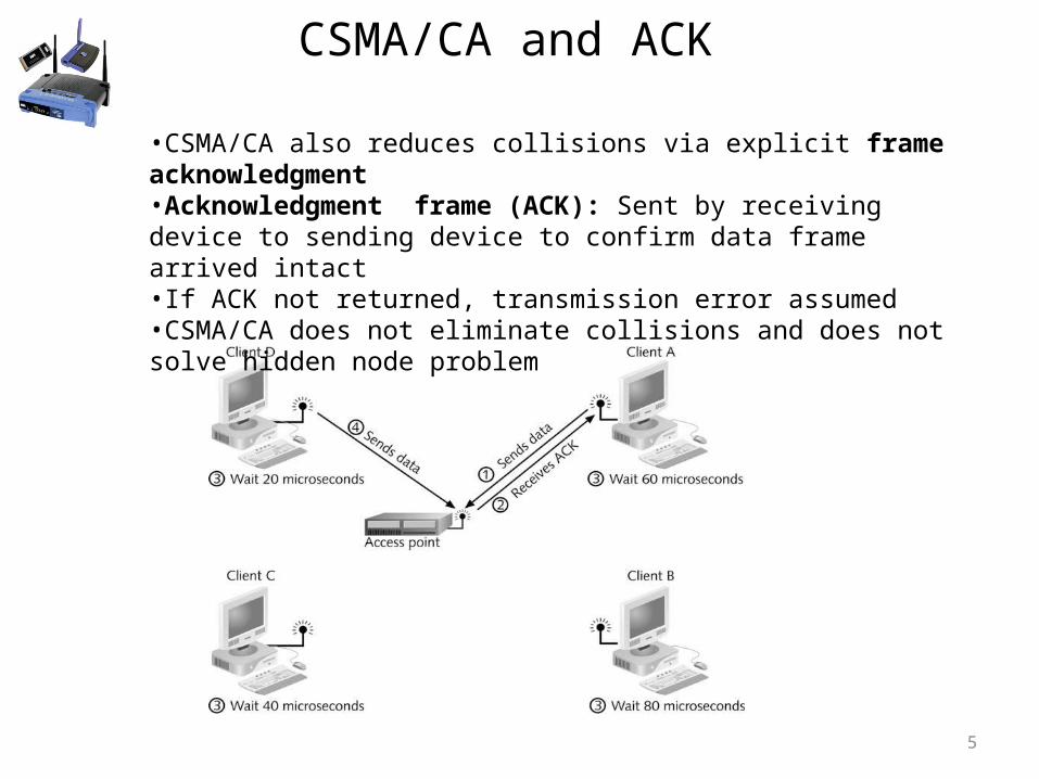
CSMA/CA and ACK
5
•CSMA/CA also reduces collisions via explicit frame acknowledgment •Acknowledgment frame (ACK): Sent by receiving device to sending device to confirm data frame arrived intact•If ACK not returned, transmission error assumed•CSMA/CA does not eliminate collisions and does not solve hidden node problem
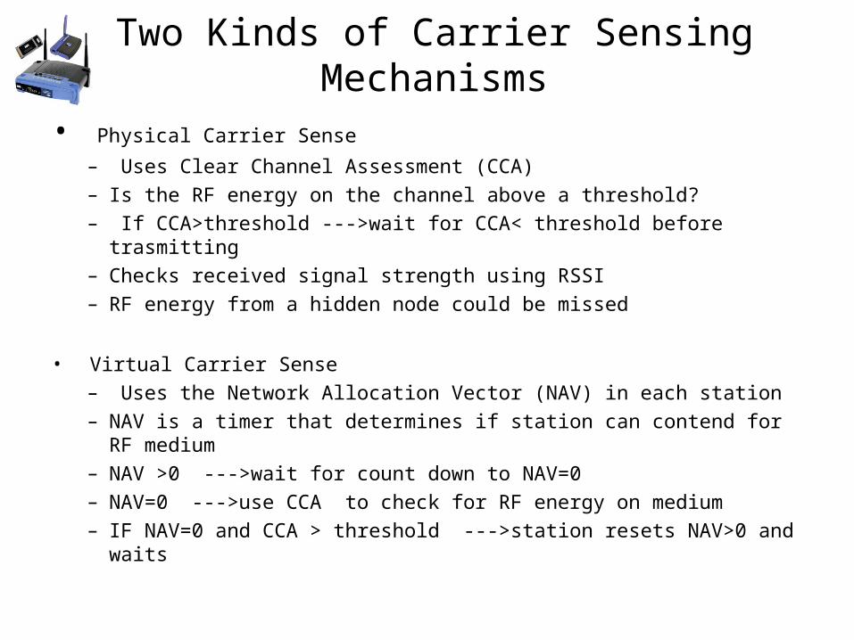
Two Kinds of Carrier Sensing Mechanisms
• Physical Carrier Sense– Uses Clear Channel Assessment (CCA) – Is the RF energy on the channel above a threshold? – If CCA>threshold --->wait for CCA< threshold before trasmitting– Checks received signal strength using RSSI– RF energy from a hidden node could be missed
• Virtual Carrier Sense– Uses the Network Allocation Vector (NAV) in each station– NAV is a timer that determines if station can contend for RF medium– NAV >0 --->wait for count down to NAV=0– NAV=0 --->use CCA to check for RF energy on medium– IF NAV=0 and CCA > threshold --->station resets NAV>0 and waits
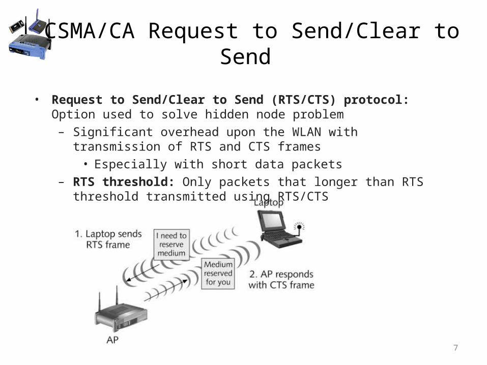
CSMA/CA Request to Send/Clear to Send
7
• Request to Send/Clear to Send (RTS/CTS) protocol: Option used to solve hidden node problem
– Significant overhead upon the WLAN with transmission of RTS and CTS frames
• Especially with short data packets– RTS threshold: Only packets that longer than RTS threshold transmitted
using RTS/CTS
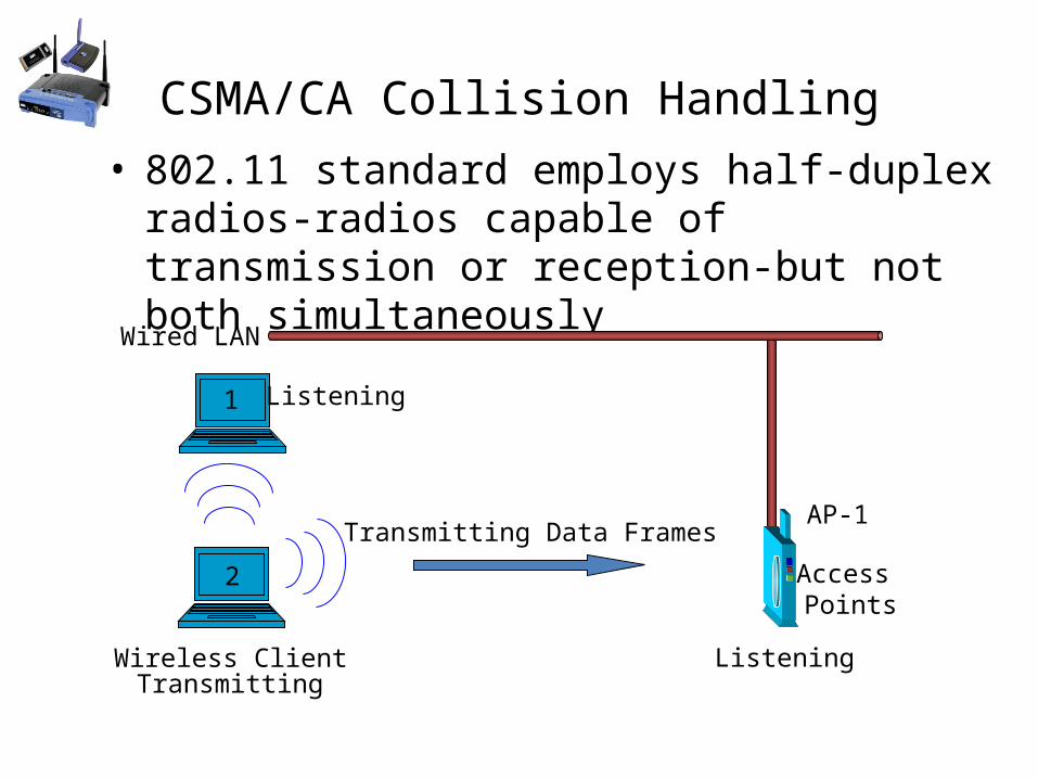
CSMA/CA Collision Handling• 802.11 standard employs half-duplex radios-radios
capable of transmission or reception-but not both simultaneously
Wireless Client
Access Points
Wired LAN
Transmitting Data Frames
1
2
AP-1
Listening
ListeningTransmitting
Interframe Spacing ensures no frame overlap and proper frame processing sequence
9
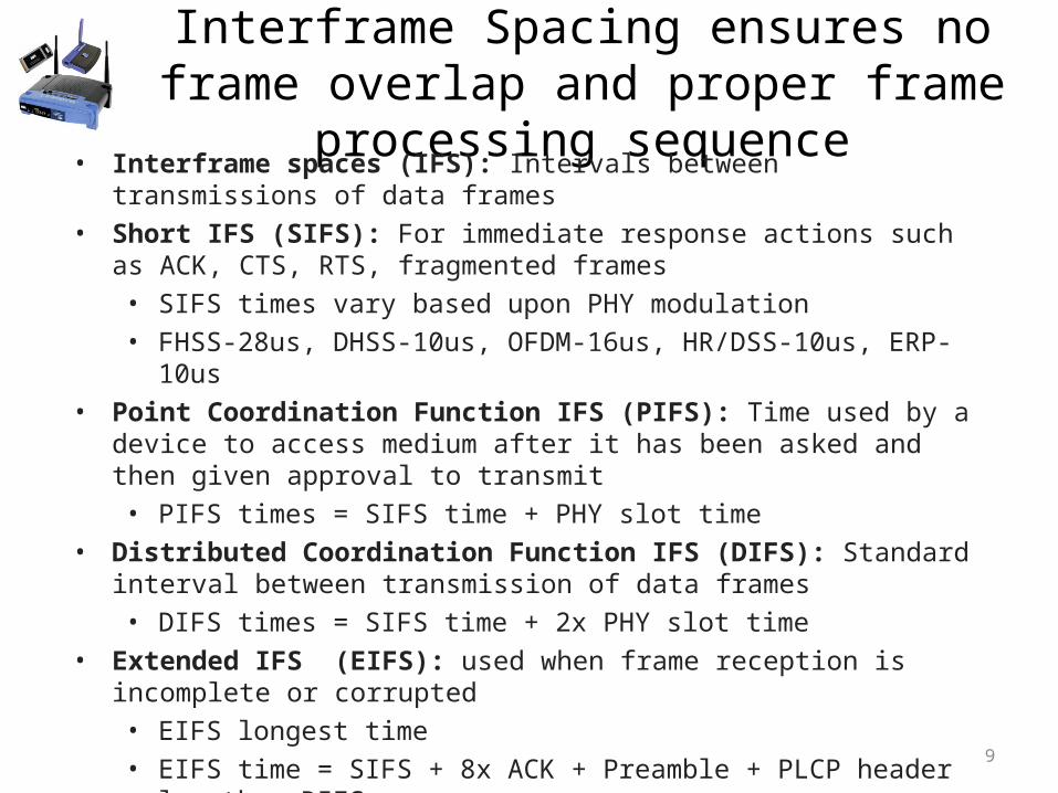
• Interframe spaces (IFS): Intervals between transmissions of data frames• Short IFS (SIFS): For immediate response actions such as ACK, CTS, RTS,
fragmented frames• SIFS times vary based upon PHY modulation• FHSS-28us, DHSS-10us, OFDM-16us, HR/DSS-10us, ERP-10us
• Point Coordination Function IFS (PIFS): Time used by a device to access medium after it has been asked and then given approval to transmit• PIFS times = SIFS time + PHY slot time
• Distributed Coordination Function IFS (DIFS): Standard interval between transmission of data frames• DIFS times = SIFS time + 2x PHY slot time
• Extended IFS (EIFS): used when frame reception is incomplete or corrupted• EIFS longest time• EIFS time = SIFS + 8x ACK + Preamble + PLCP header length + DIFS
Contention Window and Backoff Time
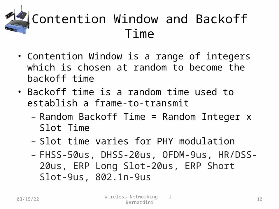
• Contention Window is a range of integers which is chosen at random to become the backoff time
• Backoff time is a random time used to establish a frame-to-transmit– Random Backoff Time = Random Integer x Slot Time– Slot time varies for PHY modulation– FHSS-50us, DHSS-20us, OFDM-9us, HR/DSS-20us, ERP Long
Slot-20us, ERP Short Slot-9us, 802.1n-9us
04/18/23 Wireless Networking J. Bernardini 10
Transmitting on the WLAN: Fragmentation
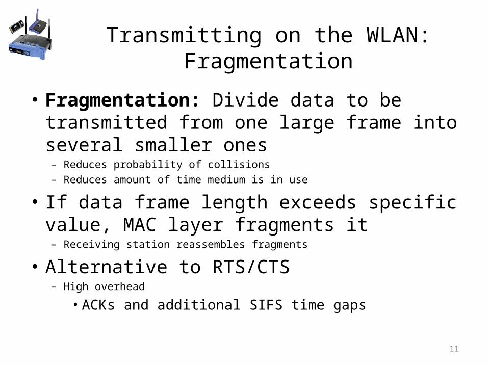
• Fragmentation: Divide data to be transmitted from one large frame into several smaller ones– Reduces probability of collisions– Reduces amount of time medium is in use
• If data frame length exceeds specific value, MAC layer fragments it– Receiving station reassembles fragments
• Alternative to RTS/CTS– High overhead
• ACKs and additional SIFS time gaps
11
IEEE 802.11 MAC Functions
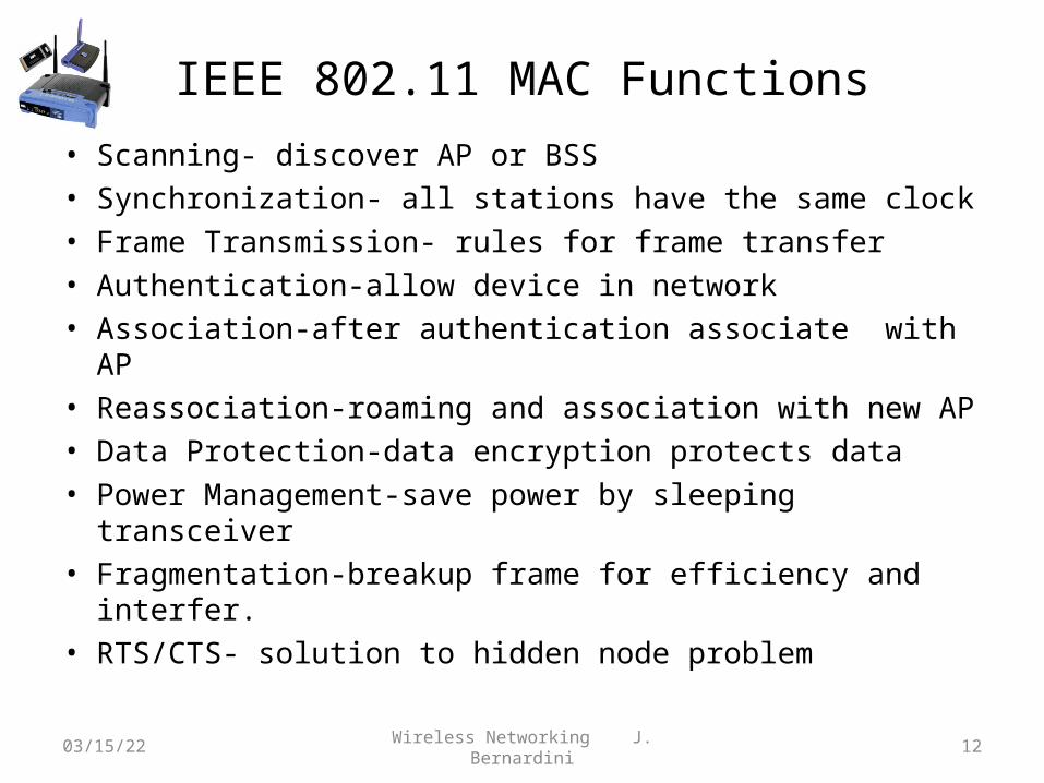
• Scanning- discover AP or BSS• Synchronization- all stations have the same clock• Frame Transmission- rules for frame transfer• Authentication-allow device in network• Association-after authentication associate with AP• Reassociation-roaming and association with new AP• Data Protection-data encryption protects data• Power Management-save power by sleeping transceiver• Fragmentation-breakup frame for efficiency and interfer.• RTS/CTS- solution to hidden node problem
04/18/23 Wireless Networking J. Bernardini 12
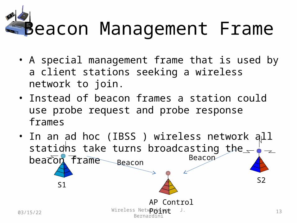
Beacon Management Frame
• A special management frame that is used by a client stations seeking a wireless network to join.
• Instead of beacon frames a station could use probe request and probe response frames
• In an ad hoc (IBSS ) wireless network all stations take turns broadcasting the beacon frame
04/18/23 Wireless Networking J. Bernardini 13
S1S2
AP Control Point
BeaconBeacon
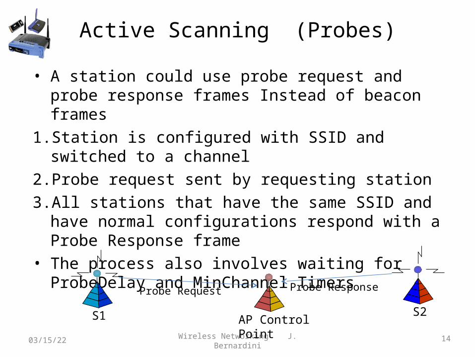
Active Scanning (Probes)
• A station could use probe request and probe response frames Instead of beacon frames
1. Station is configured with SSID and switched to a channel2. Probe request sent by requesting station3. All stations that have the same SSID and have normal
configurations respond with a Probe Response frame• The process also involves waiting for ProbeDelay and
MinChannel Timers
04/18/23 Wireless Networking J. Bernardini 14
S1 S2AP Control Point
Probe Request Probe Response
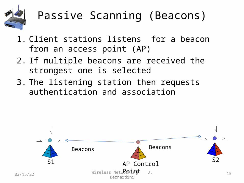
Passive Scanning (Beacons)
1. Client stations listens for a beacon from an access point (AP)2. If multiple beacons are received the strongest one is selected3. The listening station then requests authentication and
association
04/18/23 Wireless Networking J. Bernardini 15
S1 S2AP Control Point
Beacons Beacons
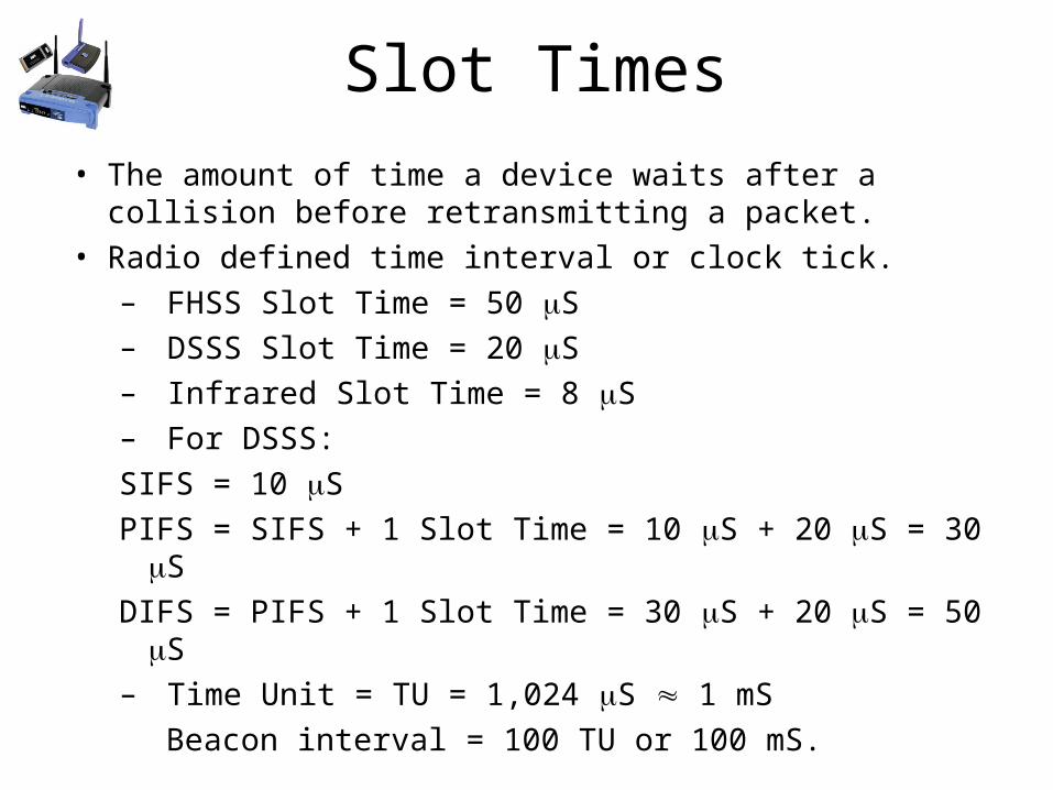
Slot Times• The amount of time a device waits after a collision before
retransmitting a packet. • Radio defined time interval or clock tick.
– FHSS Slot Time = 50 S– DSSS Slot Time = 20 S– Infrared Slot Time = 8 S– For DSSS:SIFS = 10 SPIFS = SIFS + 1 Slot Time = 10 S + 20 S = 30 SDIFS = PIFS + 1 Slot Time = 30 S + 20 S = 50 S– Time Unit = TU = 1,024 S 1 mS
Beacon interval = 100 TU or 100 mS.
Slot Time Notes• Short Slot Times - The amount of time a device waits after a collision before retransmitting a
packet. You can increase throughput on 802.11g, 2.4-GHz radios by enabling short slot time (most .11g radios enable this by default).
• Reducing the slot time from the standard 20 microseconds to the 9-microsecond short slot time decreases the overall backoff, which increases throughput.
• Backoff, which is a multiple of the slot time, is the random length of time a station waits before sending a packet on the LAN.
• Many 802.11g radios support short slot time, but some do not. • When short slot time is enabled, the wireless device uses the short slot time only when all
clients associated to the 802.11g, 2.4-GHz radio support short slot time.• Short slot time is an 802.11g-only feature and does not apply to 802.11a radios.
04/18/23 Wireless Networking J. Bernardini 17
Communications Options
• MAC Layer– Access Methods
• DCF – RTS/CTS (optional)Distributed function Wireless MACAvoids hidden node problem
• DCF – PCF (optional)AP polls stationsSuperframes to allow station to eventually get accessSuperframe = Beacon + CFP + CP CFP = Contention-Free PeriodCP = Contention Period
RTS/CTS
• Sending unicast packets– Station can send RTS with reservation parameter
after waiting for DIFS (reservation determines amount of time the data packet needs the medium)
– Acknowledgement via CTS after SIFS by receiver (if ready to receive)
– Sender can now send data at once, acknowledgement via ACK
– Other stations store medium reservations distributed via RTS and CTS
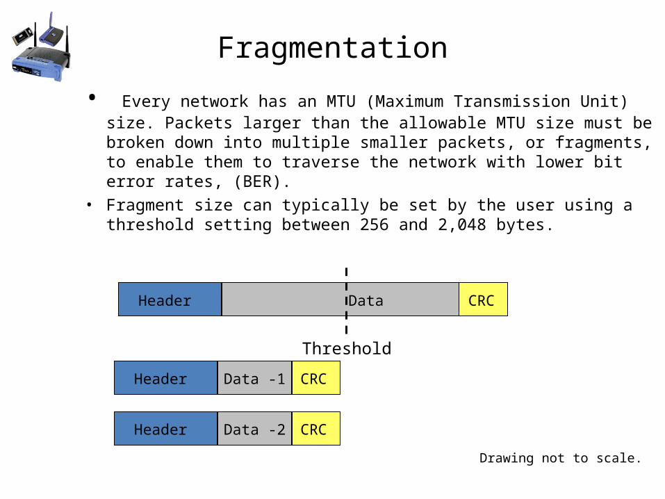
Fragmentation
• Every network has an MTU (Maximum Transmission Unit) size. Packets larger than the allowable MTU size must be broken down into multiple smaller packets, or fragments, to enable them to traverse the network with lower bit error rates, (BER).
• Fragment size can typically be set by the user using a threshold setting between 256 and 2,048 bytes.
Header Data CRC
Header Data -1 CRC
Header Data -2 CRC
Threshold
Drawing not to scale.
Dynamic Rate Switching
• Dynamic Rate Switching =Dynamic Rate Selection =Automatic Rate Shifting----All mean the same thing
• Process of reducing or increasing the data rate based upon RF signal levels
• RF signals attenuate over distance or by absorption• AP will reduce data rate for weaker signals• AP will increase data rate for higher signals
04/18/23 Wireless Networking J. Bernardini 21
Dynamic Rate Selection (DRS)
• Dynamic Rate Selection or Adaptive Rate Selection/shifting.
– 802.11a, 802.11g modes: 54, 48, 36, 24, 18, 12, 9, 6 Mbps– 802.11b mode: 11, 5.5, 2, 1 Mbps– Orinoco 2X mode: 108, 96, 72, 48, 36, 24, 18, 12 Mbps
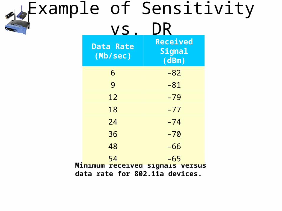
Example of Sensitivity vs. DR
Minimum received signals versus data rate for 802.11a devices.
Data Rate(Mb/sec)
ReceivedSignal (dBm)
6 –82
9 –81
12 –79
18 –77
24 –74
36 –70
48 –66
54 –65
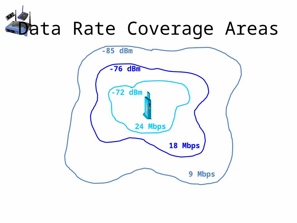
Data Rate Coverage Areas
24 Mbps
18 Mbps
9 Mbps
-72 dBm
-76 dBm
-85 dBm
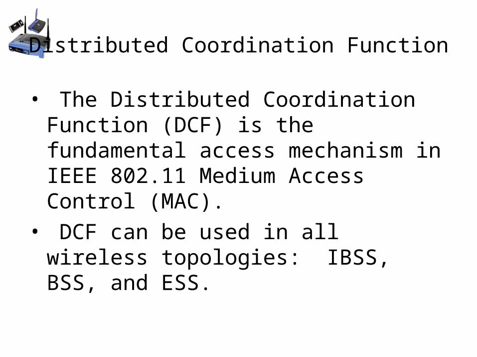
Distributed Coordination Function
• The Distributed Coordination Function (DCF) is the fundamental access mechanism in IEEE 802.11 Medium Access Control (MAC).
• DCF can be used in all wireless topologies: IBSS, BSS, and ESS.
contention
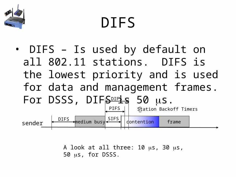
DIFS
• DIFS – Is used by default on all 802.11 stations. DIFS is the lowest priority and is used for data and management frames. For DSSS, DIFS is 50 s.
medium busysenderDIFS SIFS
PIFS Station Backoff Timers
frame
A look at all three: 10 s, 30 s, 50 s, for DSSS.
DIFS
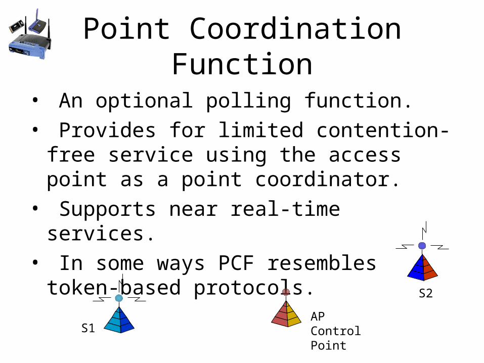
Point Coordination Function
• An optional polling function.• Provides for limited contention-free service
using the access point as a point coordinator.• Supports near real-time services.• In some ways PCF resembles token-based
protocols.
APControl Point
S1
S2
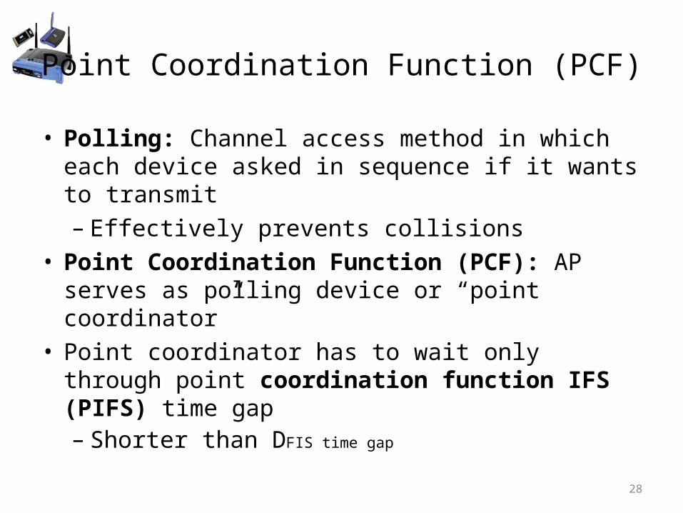
Point Coordination Function (PCF)
• Polling: Channel access method in which each device asked in sequence if it wants to transmit– Effectively prevents collisions
• Point Coordination Function (PCF): AP serves as polling device or “point coordinator”
• Point coordinator has to wait only through point coordination function IFS (PIFS) time gap– Shorter than DFIS time gap
28
PIFS
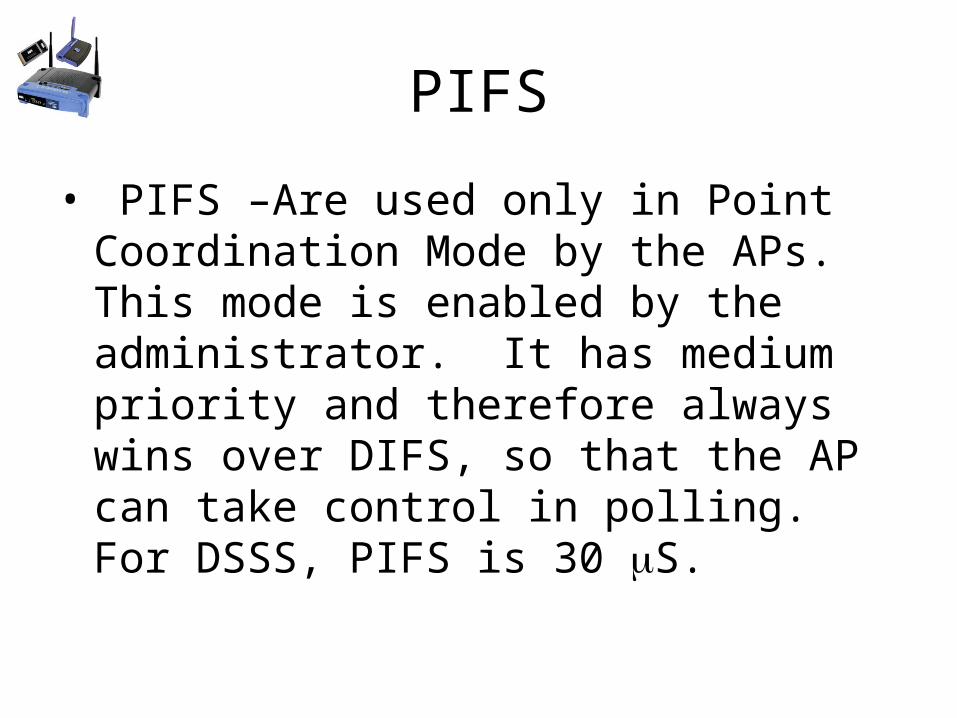
• PIFS –Are used only in Point Coordination Mode by the APs. This mode is enabled by the administrator. It has medium priority and therefore always wins over DIFS, so that the AP can take control in polling. For DSSS, PIFS is 30 S.
DIFS and DCF frames
30
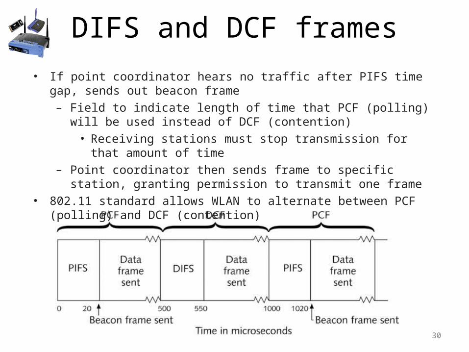
• If point coordinator hears no traffic after PIFS time gap, sends out beacon frame– Field to indicate length of time that PCF (polling) will be used instead of DCF
(contention)• Receiving stations must stop transmission for that amount of time
– Point coordinator then sends frame to specific station, granting permission to transmit one frame
• 802.11 standard allows WLAN to alternate between PCF (polling) and DCF (contention)
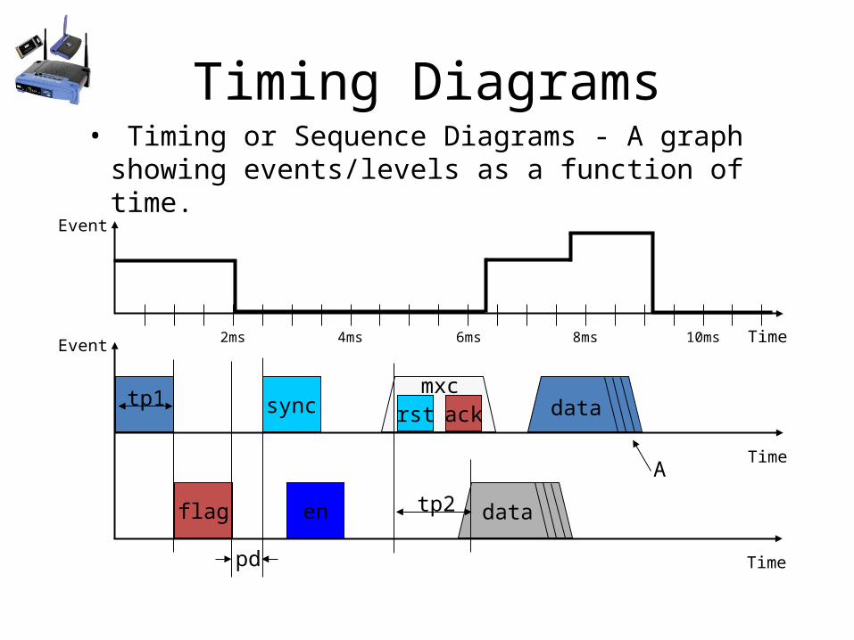
Timing Diagrams• Timing or Sequence Diagrams - A graph
showing events/levels as a function of time.
Time
Time
Event
Event 2ms 4ms 6ms 8ms 10ms
sync rst ack
Time
flag en
pd
tp2
tp1
A
data
data
mxc
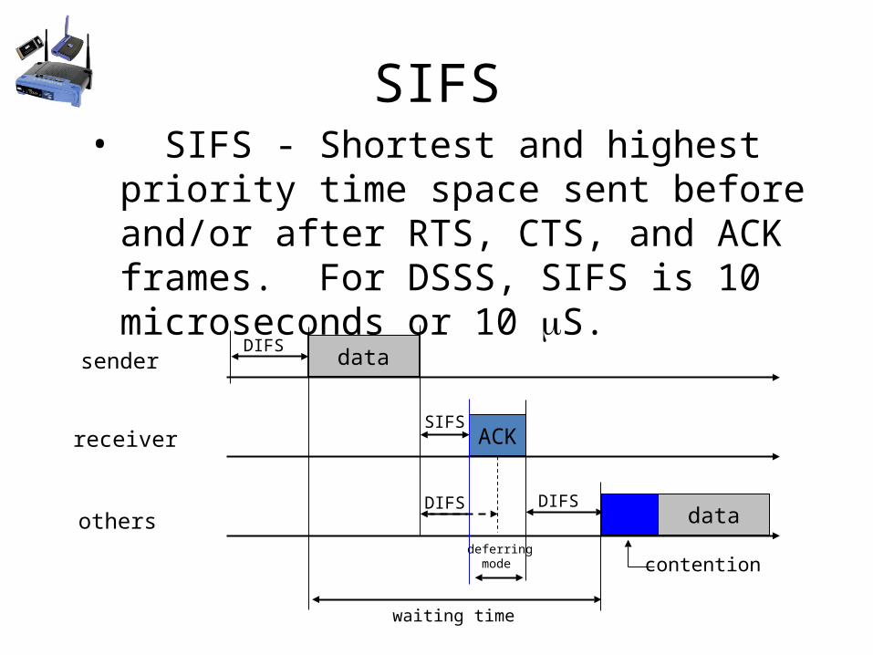
SIFS• SIFS - Shortest and highest priority time
space sent before and/or after RTS, CTS, and ACK frames. For DSSS, SIFS is 10 microseconds or 10 S.
data
ACK
data
sender
receiver
others
DIFS
SIFS
waiting time
contention
DIFS
deferring mode
DIFS
Hybrid Coordination Function (HCF)
• 802.11e add enhancements to DCF and PCF• Two channel-access methods
– Enhanced Distributed Channel Access (EDCA)– Hybrid Coordination Function Control Channel ACCESS (HCCA)
• Standard and HCF sequence:– Standard 802.11 ST (radio) transmits a frame– ST must contend for media to transmit another frame– HCF radio will be given a Transmit Opportunity (TXOP) to send
multiple frames.– During the TXOP time ST can send a Frame burst– Short Interframe Space (SIFS) is used during TXOP
04/18/23 Wireless Networking J. Bernardini 33
Enhanced Distributed Channel Access (EDCA)
• Access method that allows for eight user priorities(UP)• Traffic is prioritized using 802.1D priority tags• Priorities Categories include: • Voice (AC_VO)• Video(AC_VI)• Best Effort(AC_BE)• Background(AC_BK)• All Categories require the use of Enhanced Distributed
Channel Access Function (EDCAF) to contend for wireless medium
04/18/23 Wireless Networking J. Bernardini 34
Block Acknowledgement (BA)
• 802.11e defines the aggregation of acknowledges in to one ACK frame
• Two Block ACK mechanisms:• Immediate - for low-latency traffic• Delayed - for latency-tolerant traffic
04/18/23 Wireless Networking J. Bernardini 35
Wi-Fi Multimedia (WMM)
• 802.11e defines layer-2 methods for time-sensitive applications over 802.11 wireless
• The Wi-Fi Alliance introduced Wi-Fi Multimedia certification WMM)
• WMM is based upon EDCA • WMM uses 802.1D priority tags• Traffic is prioritized for Voice, Video, Best-Effort, Background• WMM-PS is for Power Saving or battery operated wireless
equipment.
04/18/23 Wireless Networking J. Bernardini 36


