INTRODUCTION TO WPS SYSTEM DESIGNED TO MEASURE THE CHANGE OF LOCATION FOR PAL-XFEL GIRDER*
Hyojin Choi†, Sangbong Lee, Hong-Gi Lee, Kwang Won Seo, Kyehwan Gil, Heung-Sik Kang Department of Accelerator, PAL-XFEL, Pohang, Korea
Abstract To maintain stable electron beam parameters (Energy
10GeV, Charge 200pC, Bunch Length 60fs, Emittance X/Y 0.481mm/0.256mm mrad), PAL-XFEL equipment should keep the alignment of accelerator (±100m) and undulator (±50m) constant. To ensure the precise measurement and alignment of PAL-XFEL, GPS-based surface geodetic network and the installation of a tunnel measurement network inside buildings was prepared and the fiducialization of major equipment was completed. After PAL-XFEL equipment is aligned, if the ground and buildings go through vertical changes during operation, tilt and misalignment of equipments (correct magnet, BPM, accelerator) will cause errors in the electron beam trajectory, which will lead to changes in the beam parameter. Hydrostatic Levelling System (HLS) was installed to measure vertical changes in buildings and the ground (sinking and uplifting) continuously and systematically, and Wire Position System (WPS) installed to measure changes in Girder. This paper introduces the operation principle, design concept, installation status, and operation status of WPS.
INTRODUCTION James Clerk Maxwell combined Gauss' law for
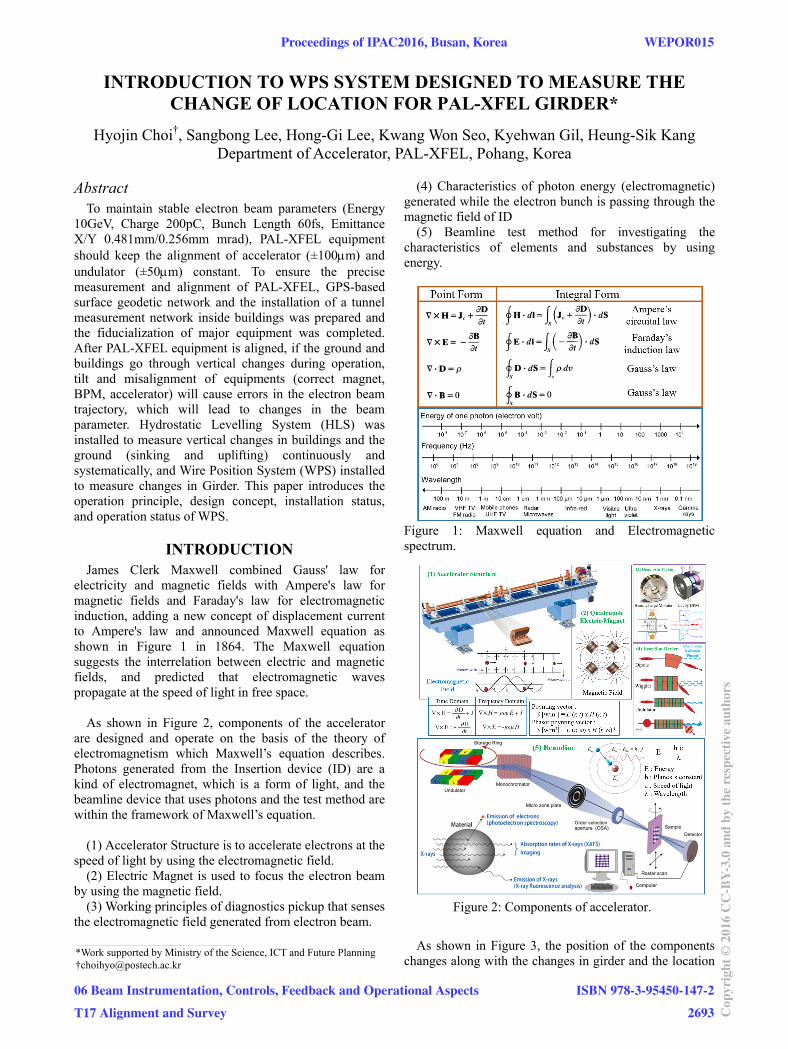
electricity and magnetic fields with Ampere's law for magnetic fields and Faraday's law for electromagnetic induction, adding a new concept of displacement current to Ampere's law and announced Maxwell equation as shown in Figure 1 in 1864. The Maxwell equation suggests the interrelation between electric and magnetic fields, and predicted that electromagnetic waves propagate at the speed of light in free space.
As shown in Figure 2, components of the accelerator are designed and operate on the basis of the theory of electromagnetism which Maxwell’s equation describes. Photons generated from the Insertion device (ID) are a kind of electromagnet, which is a form of light, and the beamline device that uses photons and the test method are within the framework of Maxwell’s equation.
(1) Accelerator Structure is to accelerate electrons at the
speed of light by using the electromagnetic field. (2) Electric Magnet is used to focus the electron beam
by using the magnetic field. (3) Working principles of diagnostics pickup that senses
the electromagnetic field generated from electron beam.
(4) Characteristics of photon energy (electromagnetic) generated while the electron bunch is passing through the magnetic field of ID
(5) Beamline test method for investigating the characteristics of elements and substances by using energy.
Figure 1: Maxwell equation and Electromagnetic spectrum.
Figure 2: Components of accelerator.
As shown in Figure 3, the position of the components
changes along with the changes in girder and the location
of the ground which a building stands on. When the position of the components moves out of the orbit of the electron beam due to changes in the ground, interaction between the electromagnet field of the component and electron beam also changes. The higher the frequency of microwaves and the stronger the electromagnetic field or magnetic field, the greater the influence of changes in position.
Figure 3: Three vibration patterns which generate relative displacement [1].
In Korea, there is a saying that goes "It takes more
than pearls to make a necklace." It means that no one will get the performance as he/she wants if he/she does not arrange and position all devices precisely even though each of the devices works well. In PAL-XFEL, the HLS and WPS are installed and operated to observe and record changes in the ground and building through continuous measurement and to quickly arrange devices in the region where significant displacement is shown.
HISTORY OF WPS TO HAVE USED ON THE ACCELERATOR
In 1990, the concept of a wire measurement system was first introduced to observe the changes in the ground of a 10-km-long linear collider [2]. The method for transmitting the RF signal to the wire and comparing the strength of the RF signals at the Pickup which is the same as the BPM was also examined in 1993. In this case, impedance around a wire should be kept constant at 50-ohm to transmit the RF signal over a distance over 100m [3]. In 1995, the European synchrotron radiation facility (ESRF) succeeded in researching and developing a non-contact mono axe (1D) WPS sensor using carbon wire [4]. After that, FOGALE Nanotech developed and commercialized the WPS2D sensor.
To establish and operate large scientific instruments
including linear colliders, various sensors should be developed for the steady observation of changes in the position of the instruments as a result of changes in the ground [5]. Recently, the Compact Linear Collider (CLIC) studied the method for real-time measurement and recording of changes in the ground of instruments several kilometres in length by using WPS and HLS [6].
WORKING PRINCIPLE OF WPS SENSOR The working principle of the WPS sensor, which is to
measure a distance in a non-contact way, is described in Figure 4. The capacitor AC voltage divider rule, which is widely used as a measurement of distance in various fields, is also applied to WPS. Voltage divider circuits may be constructed from reactive components just as easily as they may be constructed from fixed resistors, and just like resistors, a capacitive voltage divider is not affected by changes in the supply frequency even though they use capacitors which are reactive elements [7][8]. WPS are used for measuring the displacement of the sensor with respect to a stretched wire, which serves as straightness reference. Horizontal and vertical movements can be measured with these sensors. The capacitive sensors have a working range of 10 mm for each axis with a resolution of minor 0.1 m and a repeatability of about 1 m with integrated electronics. The data acquisition rate can be up to 10 Hz. In addition to the sensor, the signal conditioning box and cables compose the calibrated sensor unit. It has two electrodes per axis facing each other, which makes a total of four electrodes. The sensor can be treated as a pair of double capacitors in differential configuration. FOGALE Nanotech sets and provides the Voltage AC frequency (4~10KHz) of electronics. The first WPS have a frequency of 4KHz and the other WPS have a frequency increased by step of 0.1KHz.
Figure 4: Working principle of WPS sensor.
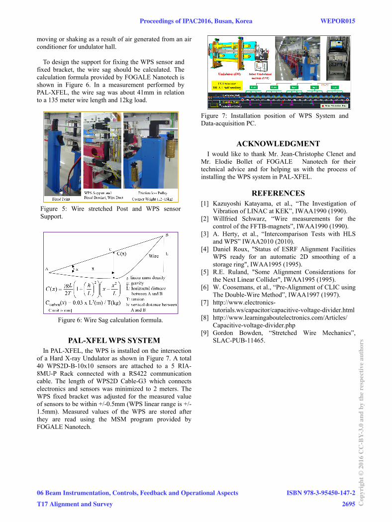
WPS REFERENCE: WIRE The most important thing in the WPS system is a
carbon wire which is used as a reference for measurement. As the post which is used to hold up a wire is installed on the ground, changes in the ground where the post is installed and the angle of the post should be measured regularly. Movement of the wire post means a change of reference. Carbon PEEK wire (diameter 0.4mm, linear mass density 235g/km) manufactured and marketed in Japan is used with 10~15kg weights [4][9]. As shown in Figure 5, a precise wire stretcher (PDL-WPS/15) provided by FOGALE Nanotech was installed on the post and wire was connected to it. A wire protection duct is installed to prevent the wire from
06 Beam Instrumentation, Controls, Feedback and Operational Aspects
T17 Alignment and Survey
moving or shaking as a result of air generated from an air conditioner for undulator hall.
To design the support for fixing the WPS sensor and
fixed bracket, the wire sag should be calculated. The calculation formula provided by FOGALE Nanotech is shown in Figure 6. In a measurement performed by PAL-XFEL, the wire sag was about 41mm in relation to a 135 meter wire length and 12kg load.
Figure 5: Wire stretched Post and WPS sensor Support.
Figure 6: Wire Sag calculation formula.
PAL-XFEL WPS SYSTEM In PAL-XFEL, the WPS is installed on the intersection
of a Hard X-ray Undulator as shown in Figure 7. A total 40 WPS2D-B-10x10 sensors are attached to a 5 RIA-8MU-P Rack connected with a RS422 communication cable. The length of WPS2D Cable-G3 which connects electronics and sensors was minimized to 2 meters. The WPS fixed bracket was adjusted for the measured value of sensors to be within +/-0.5mm (WPS linear range is +/- 1.5mm). Measured values of the WPS are stored after they are read using the MSM program provided by FOGALE Nanotech.
Figure 7: Installation position of WPS System and Data-acquisition PC.
ACKNOWLEDGMENT I would like to thank Mr. Jean-Christophe Clenet and
Mr. Elodie Bollet of FOGALE Nanotech for their technical advice and for helping us with the process of installing the WPS system in PAL-XFEL.
REFERENCES [1] Kazuyoshi Katayama, et al., “The Investigation of
Vibration of LINAC at KEK”, IWAA1990 (1990). [2] Willfried Schwarz, “Wire measurements for the
control of the FFTB-magnets”, IWAA1990 (1990). [3] A. Herty, et al., “Intercomparison Tests with HLS
and WPS” IWAA2010 (2010). [4] Daniel Roux, "Status of ESRF Alignment Facilities
WPS ready for an automatic 2D smoothing of a storage ring", IWAA1995 (1995).
[5] R.E. Ruland, "Some Alignment Considerations for the Next Linear Collider", IWAA1995 (1995).
[6] W. Coosemans, et al., “Pre-Alignment of CLIC using The Double-Wire Method”, IWAA1997 (1997).


![towaservice.up.seesaa.net...WPS/W 3830 WPS/W1712 WT2670 WPM/WT 2679 WPM '2007 iFR (W 4144 wps T 7644 C) '2006 reddotn (W 4144 wps T 9246 C) >R2006 Focus in silver] (W 4144 WPS) design](https://static.documents.pub/doc/80x56/6134f637dfd10f4dd73c10d7/-wpsw-3830-wpsw1712-wt2670-wpmwt-2679-wpm-2007-ifr-w-4144-wps-t-7644-c.jpg)


