24
Ankur Tomar– Global Technology Centre Volume 1, July 2011 Introduction to Zibgbee Technology

Ankur Tomar– Global Technology Centre
Volume 1, July 2011
Introduction to Zibgbee
Technology
Introduction to Zigbee Technology Page 2
1. Introduction
ZigBee is the most popular industry wireless mesh networking standard
for connecting sensors, instrumentation and control systems. ZigBee, a specification for communication in a wireless personal area network
(WPAN), has been called the "Internet of things." Theoretically, your ZigBee-enabled coffee maker can communicate with your ZigBee-enabled
toaster. ZigBee is an open, global, packet-based protocol designed to provide an easy-to-use architecture for secure, reliable, low power
wireless networks. ZigBee and IEEE 802.15.4 are low data rate wireless
networking standards that can eliminate the costly and damage prone wiring in industrial control applications. Flow or process control equipment
can be place anywhere and still communicate with the rest of the system. It can also be moved, since the network doesn't care about the physical
location of a sensor, pump or valve.
The ZigBee RF4CE standard enhances the IEEE 802.15.4 standard by providing a simple networking layer and standard application profiles that
can be used to create interoperable multi-vendor consumer electronic solutions.
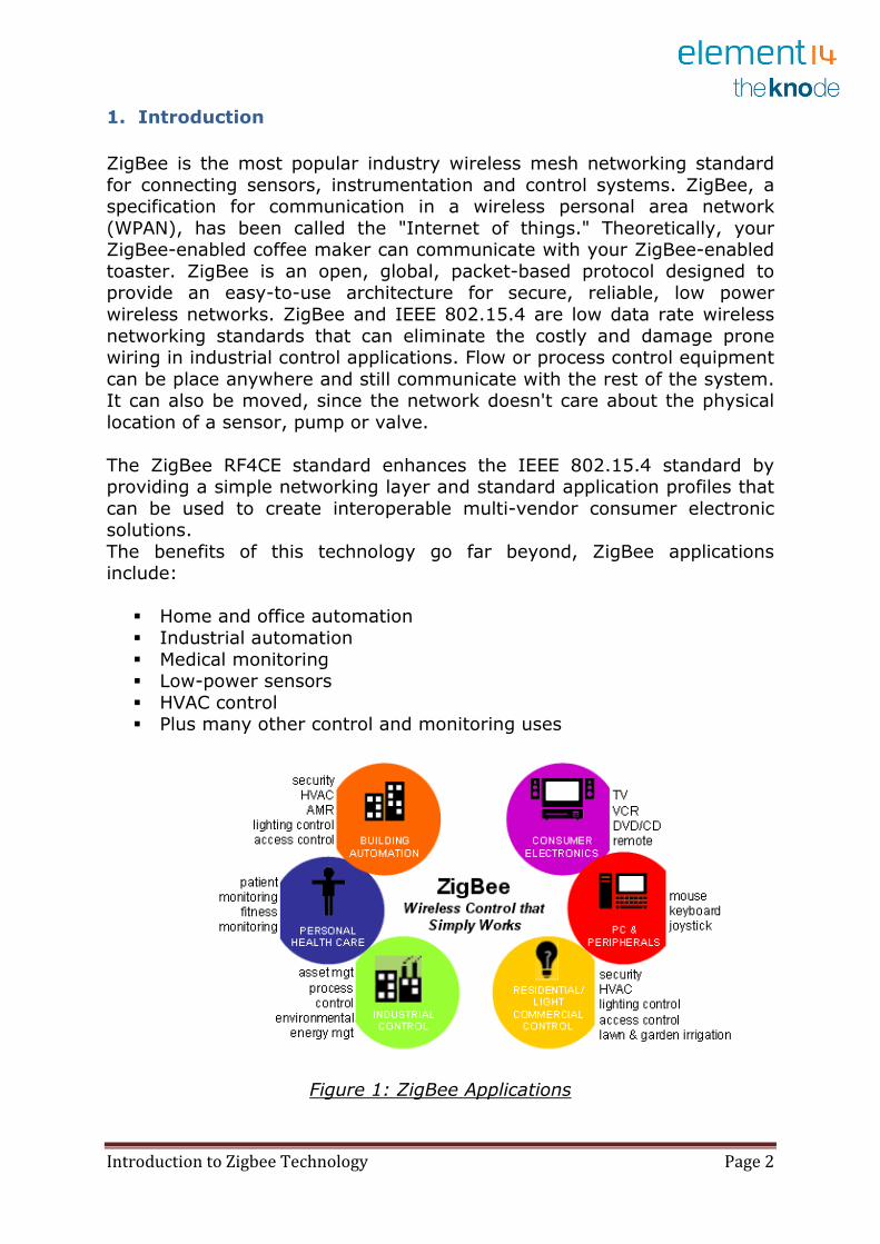
The benefits of this technology go far beyond, ZigBee applications include:
� Home and office automation
� Industrial automation
� Medical monitoring � Low-power sensors
� HVAC control � Plus many other control and monitoring uses
Figure 1: ZigBee Applications
Introduction to Zigbee Technology Page 3
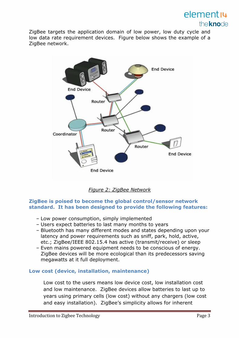
ZigBee targets the application domain of low power, low duty cycle and
low data rate requirement devices. Figure below shows the example of a ZigBee network.
Figure 2: ZigBee Network
ZigBee is poised to become the global control/sensor network standard. It has been designed to provide the following features:
– Low power consumption, simply implemented
– Users expect batteries to last many months to years
– Bluetooth has many different modes and states depending upon your latency and power requirements such as sniff, park, hold, active,
etc.; ZigBee/IEEE 802.15.4 has active (transmit/receive) or sleep – Even mains powered equipment needs to be conscious of energy.
ZigBee devices will be more ecological than its predecessors saving megawatts at it full deployment.
Low cost (device, installation, maintenance)
Low cost to the users means low device cost, low installation cost
and low maintenance. ZigBee devices allow batteries to last up to
years using primary cells (low cost) without any chargers (low cost
and easy installation). ZigBee’s simplicity allows for inherent
Introduction to Zigbee Technology Page 4
configuration and redundancy of network devices provides low
maintenance.
High density of nodes per network
ZigBee’s use of the IEEE 802.15.4 PHY and MAC allows networks to
handle any number of devices. This attribute is critical for massive
sensor arrays and control networks.
Simple protocol, global implementation
ZigBee’s protocol code stack is estimated to be about 1/4th of
Bluetooth’s or 802.11’s. Simplicity is essential to cost,
interoperability, and maintenance. The IEEE 802.15.4 PHY adopted
by ZigBee has been designed for the 868 MHz band in Europe, the
915 MHz band in N America, Australia, etc; and the 2.4 GHz band is
now recognized to be a global band accepted in almost all countries.
2. Wireless Communication
All wireless communication systems have the following components:
� Transmitter � Receiver
� Antennas � Path between the transmitter and the receiver
In short, the transmitter feeds a signal of encoded data modulated
into RF waves into the antenna. The antenna radiates the signal through the air where it is picked up by the antenna of the receiver. The receiver
demodulates the RF waves back into the encoded data stream sent by the
transmitter.
2.2 Wireless Network Types
There are a number of different types of networks used in wireless
communication. Network types are typically defined by size and location.

Introduction to Zigbee Technology Page 5
2.2.1 WPAN
A wireless personal area network (WPAN) is meant to span a small area
such as a private home or an individual workspace. It is used to communicate over a relatively short distance. The specification does not
preclude longer ranges being achieved with the trade-off of a lower data rate.
In contrast to other network types, there is little to no need for infrastructure with a WPAN.
Ad-hoc networking is one of the key concepts in WPANs. This allows
devices to be part of the network temporarily; they can join and leave at will. This works well for mobile devices like PDAs, laptops and phones.
Some of the protocols employing WPAN include Bluetooth, ZigBee, Ultra-wideband (UWB) and IrDA. Each of these is optimized for particular
applications or domains. ZigBee, with its sleepy, battery-powered end devices, is a perfect fit for wireless sensors. Typical ZigBee application
domains include: agricultural, building and industrial automation, home control, medical monitoring, security and, lest we take ourselves too
seriously, toys, toys and more toys.
2.2.2 WLAN
Wireless local area networks (WLANs) are meant to span a relatively
small area, e.g., a house, a building, or a college campus. WLANs are becoming more prevalent as costs come down and standards improve.
A WLAN can be an extension of a wired local area network (LAN), its
access point connected to a LAN technology such as Ethernet. A popular protocol for WLAN is 802.11, also known as Wi-Fi.
2.2.3 WWAN
A wireless wide area network (WAN) is meant to span a large area, such as a city, state or country. It makes use of telephone lines and satellite
dishes as well as radio waves to transfer data.
2.3 Wireless Network Topologies
This section discusses the network topologies supported by the IEEE 802.15.4 and ZigBee specifications. The topology of a network describes
how the nodes are connected, either physically or logically.
Introduction to Zigbee Technology Page 6
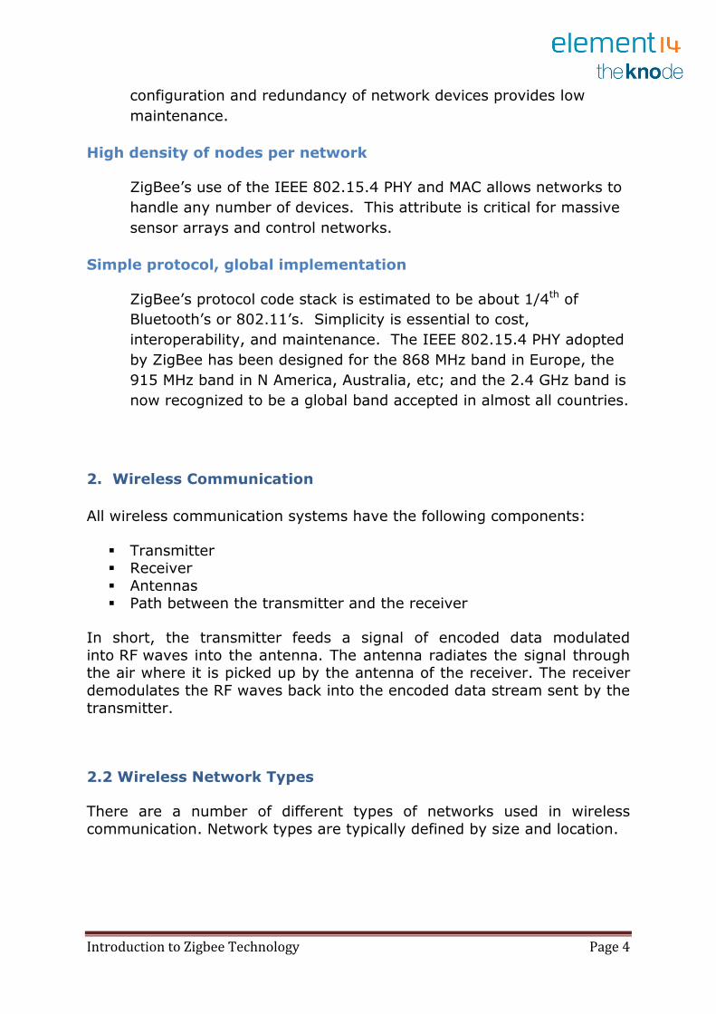
The physical topology is a geometrical shape resulting from the physical
links from node to node, as shown in the figure below. The logical topology maps the flow of data between the nodes.
Figure 3: ZigBee Network Topology
IEEE 802.15.4 supports star and peer-to-peer topologies. The ZigBee
specification supports star and two kinds of peer-to-peer topologies, mesh
and cluster tree.
ZigBee-compliant devices are sometimes specified as supporting point-to-
point and point-to-multipoint topologies.
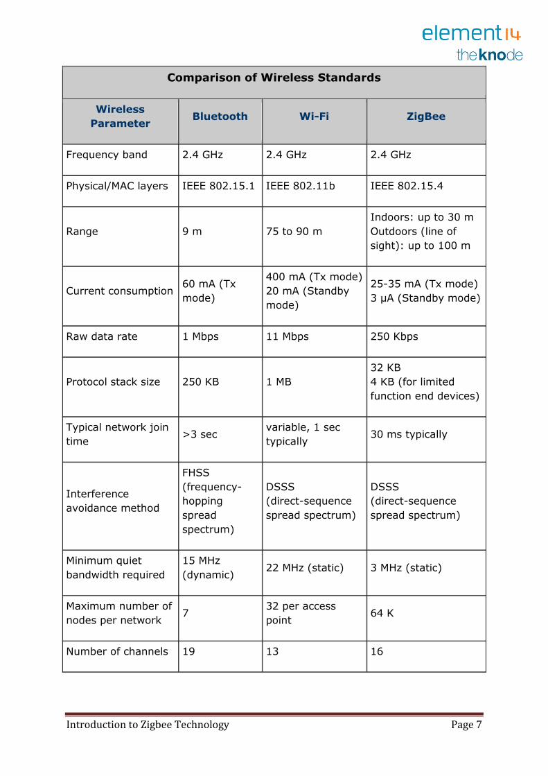
2.4 Wireless Standards
The demand for wireless solutions continues to grow and with it new standards have come forward and other existing standards have
strengthened their position in the marketplace. This section compares three popular wireless standards being used today and lists some of the
design considerations that differentiate them.
Introduction to Zigbee Technology Page 7
Comparison of Wireless Standards
Wireless
Parameter Bluetooth Wi-Fi ZigBee
Frequency band 2.4 GHz 2.4 GHz 2.4 GHz
Physical/MAC layers IEEE 802.15.1 IEEE 802.11b IEEE 802.15.4
Range 9 m 75 to 90 m
Indoors: up to 30 m
Outdoors (line of
sight): up to 100 m
Current consumption 60 mA (Tx
mode)
400 mA (Tx mode)
20 mA (Standby
mode)
25-35 mA (Tx mode)
3 µA (Standby mode)
Raw data rate 1 Mbps 11 Mbps 250 Kbps
Protocol stack size 250 KB 1 MB
32 KB
4 KB (for limited
function end devices)
Typical network join
time >3 sec
variable, 1 sec
typically 30 ms typically
Interference
avoidance method
FHSS
(frequency-
hopping
spread
spectrum)
DSSS
(direct-sequence
spread spectrum)
DSSS
(direct-sequence
spread spectrum)
Minimum quiet
bandwidth required
15 MHz
(dynamic) 22 MHz (static) 3 MHz (static)
Maximum number of
nodes per network 7
32 per access
point 64 K
Number of channels 19 13 16
Introduction to Zigbee Technology Page 8
Each wireless standard addresses the needs of a different market
segment. Choosing the best-fit wireless standard is a crucial step in the successful deployment of any wireless application. The requirements of
your application will determine the wireless standard to choose.
2.5 Security in a Wireless Network
This section discusses the added security issues introduced by wireless networks. The salient fact that, signals are travelling through the air means that the communication is less secure than if they were travelling
through wires. Someone seeking access to your network need not overcome the obstacle of tapping into physical wires. Anyone in range of
the transmission can potentially listen on the channel.
Wireless or not, a network needs a security plan. The first thing to do is to
decide what level of security is appropriate for the applications running on your network. For instance, a financial institution, such as a bank or credit
union offering online account access would have substantially different security concerns than would a business owner offering free Internet
access at a coffee shop.
2.5.1 Security Risks
After you have decided the level of security you need for your network, assess the potential security risks that exist.
� Who is in range of the wireless transmissions?
� Can unauthorized users join the network? � What would an unauthorized user be able to do if they did join?
� Is sensitive data traveling over the wireless channel?
3. Zigbee Network Devices and their Operating Modes
Two types of devices can participate in a LR-WPAN: a full function device (FFD) and a reduced function device (RFD).
An RFD does not have routing capabilities. RFDs can be configured as end
nodes only. They communicate with their parent, which is the node that allowed the RFD to join the network.
An FFD has routing capabilities and can be configured as the PAN coordinator. In a star network all nodes communicate with the PAN
coordinator only so it does not matter if they are FFDs or RFDs. In a peer-to-peer network there is also one PAN coordinator, but there are other
Introduction to Zigbee Technology Page 9
FFDs which can communicate with not only the PAN coordinator, but also
with other FFDs and RFDs.
There are three operating modes supported by IEEE 802.15.4: PAN coordinator, coordinator, and end device. FFDs can be configured for any
of the operating modes. In ZigBee terminology the PAN coordinator is referred to as simply "coordinator." The IEEE term "coordinator" is the
ZigBee term for "router."
3.1 How Zigbee Works?
ZigBee basically uses digital radios to allow devices to communicate with one another. A typical ZigBee network consists of several types of
devices. A network coordinator is a device that sets up the network, is aware of all the nodes within its network, and manages both the
information about each node as well as the information that is being transmitted/received within the network. Every ZigBee network must
contain a network coordinator. Other Full Function Devices (FFD's) may be found in the network, and these devices support all of the 802.15.4
functions. They can serve as network coordinators, network routers, or as devices that interact with the physical world. The final device found in
these networks is the Reduced Function Device (RFD), which usually only serve as devices that interact with the physical world.
As mentioned above several topologies are supported by ZigBee, including star, mesh, and cluster tree. As can be seen in above figure 3,
star topology is most useful when several end devices are located close together so that they can communicate with a single router node. That
node can then be a part of a larger mesh network that ultimately
communicates with the network coordinator. Mesh networking allows for redundancy in node links, so that if one node goes down, devices can find
an alternative path to communicate with one another.
4. IEEE 802.15.4 Specification
This chapter is an overview of the IEEE 802.15.4 specification. 802.15.4
defines a standard for a low-rate WPAN (LR-WPAN).
4.1 Scope of 802.15.4
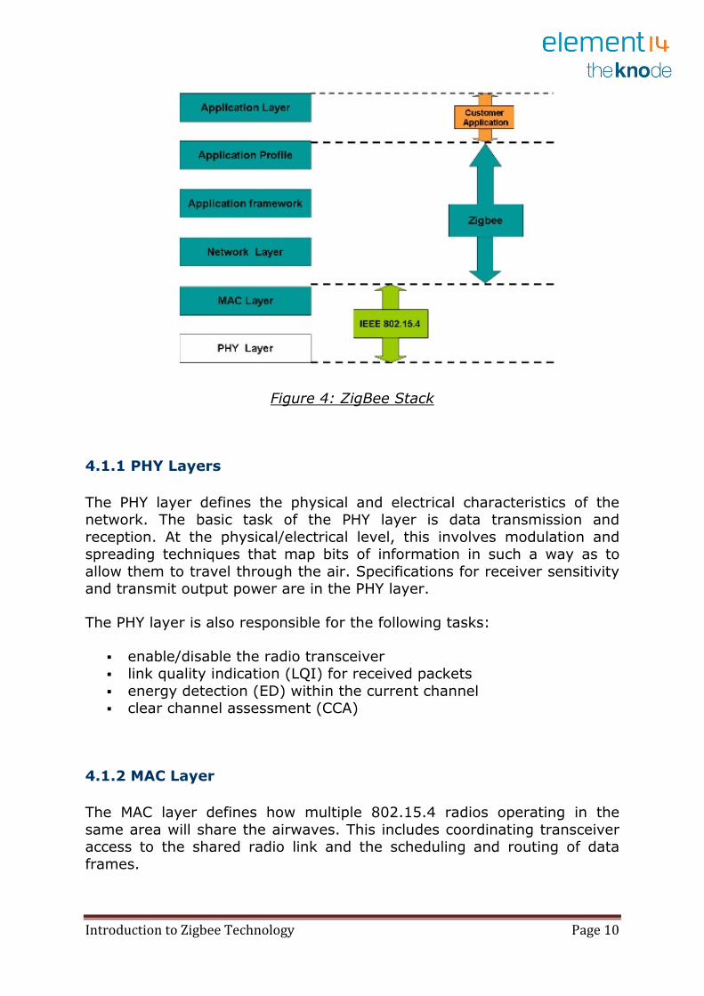
802.15.4 is a packet-based radio protocol. It addresses the communication needs of wireless applications that have low data rates and low power consumption requirements. It is the foundation on which
ZigBee is built. Figure 4 shows a simplified ZigBee stack, which includes
the two layers specified by 802.15.4: the physical (PHY) and MAC layers.
Introduction to Zigbee Technology Page 10
Figure 4: ZigBee Stack
4.1.1 PHY Layers
The PHY layer defines the physical and electrical characteristics of the network. The basic task of the PHY layer is data transmission and
reception. At the physical/electrical level, this involves modulation and spreading techniques that map bits of information in such a way as to
allow them to travel through the air. Specifications for receiver sensitivity and transmit output power are in the PHY layer.
The PHY layer is also responsible for the following tasks:
� enable/disable the radio transceiver � link quality indication (LQI) for received packets
� energy detection (ED) within the current channel � clear channel assessment (CCA)
4.1.2 MAC Layer
The MAC layer defines how multiple 802.15.4 radios operating in the
same area will share the airwaves. This includes coordinating transceiver access to the shared radio link and the scheduling and routing of data
frames.
Introduction to Zigbee Technology Page 11
There are network association and disassociation functions embedded in
the MAC layer. These functions support the self-configuration and peer-to-peer communication features of a ZigBee network.
The MAC layer is responsible for the following tasks:
� beacon generation if device is a coordinator
� implementing carrier sense multiple access with collision avoidance
(CSMA-CA) � handling guaranteed time slot (GTS) mechanism
� data transfer services for upper layers
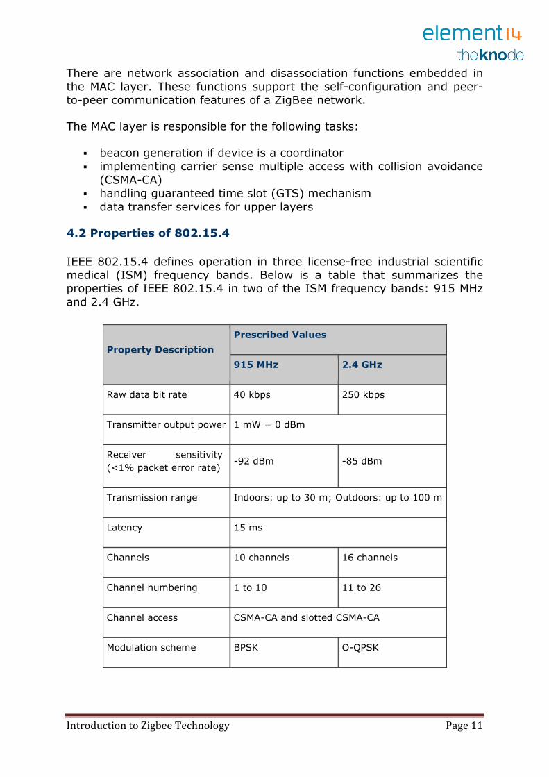
4.2 Properties of 802.15.4
IEEE 802.15.4 defines operation in three license-free industrial scientific medical (ISM) frequency bands. Below is a table that summarizes the properties of IEEE 802.15.4 in two of the ISM frequency bands: 915 MHz
and 2.4 GHz.
Property Description
Prescribed Values
915 MHz 2.4 GHz
Raw data bit rate 40 kbps 250 kbps
Transmitter output power 1 mW = 0 dBm
Receiver sensitivity
(<1% packet error rate) -92 dBm -85 dBm
Transmission range Indoors: up to 30 m; Outdoors: up to 100 m
Latency 15 ms
Channels 10 channels 16 channels
Channel numbering 1 to 10 11 to 26
Channel access CSMA-CA and slotted CSMA-CA
Modulation scheme BPSK O-QPSK
Introduction to Zigbee Technology Page 12
4.2.1 Transmitter and Receiver
The power output of the transmitter and the sensitivity of the receiver are determining factors of the signal strength and its range. Other factors include any obstacles in the communication path that cause interference
with the signal.
The higher the transmitter's output power, the longer the range of its
signal. On the other side, the receiver's sensitivity determines the minimum power needed for the radio to reliably receive the signal. These
values are described using dBm, a relative measurement that compares two signals with 1 milliwatt used as the reference signal. A large negative
dBm number means higher receiver sensitivity.
4.2.2 Channels
Of the three ISM frequency bands only the 2.4 GHz band operates world-wide. The 868 MHz band only operates in the EU and the 915 MHz band is
only for North and South America. However, if global interoperability is not a requirement, the relative emptiness of the 915 MHz band in non-
European countries might be an advantage for some applications.
For the 2.4 GHz band, IEEE 802.15.4 specifies communication should occur in 5 MHz channels ranging from 2.405 to 2.480 GHz.
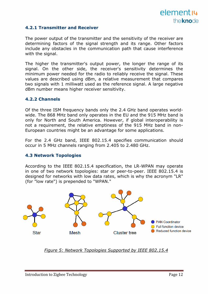
4.3 Network Topologies
According to the IEEE 802.15.4 specification, the LR-WPAN may operate
in one of two network topologies: star or peer-to-peer. IEEE 802.15.4 is designed for networks with low data rates, which is why the acronym "LR"
(for "low rate") is prepended to "WPAN."
Figure 5: Network Topologies Supported by IEEE 802.15.4

Introduction to Zigbee Technology Page 13
As shown in figure 5 above, the star topology has a central node with all
other nodes communicating only with the central one. The peer-to-peer topology allows peers to communicate directly with one another. This
feature is essential in supporting mesh networks.
4.4 Addressing Modes Supported by 802.15.4
IEEE 802.15.4 supports both short (16-bit) and extended (64-bit) addressing. An extended address is assigned to every RF module that complies with the 802.15.4 specification. When a device associates with a
WPAN it can receive a 16-bit address from its parent node that is unique in that network.
4.4.1 PAN ID
Each WPAN has a 16-bit number that is used as a network identifier. It is called the PAN ID. The PAN coordinator assigns the PAN ID when it creates the network. A device can try and join any network or it can limit
itself to a network with a particular PAN ID.
ZigBee PRO defines an extended PAN ID. It is a 64-bit number that is
used as a network identifier in place of its 16-bit predecessor.
5. ZigBee Specification
ZigBee, its specification
and promotion, is a product of the ZigBee
Alliance. The Alliance is an association of
companies working together to ensure the
success of this open global standard.
ZigBee is built on top of the IEEE 802.15.4
standard. ZigBee provides routing and
multi-hop functions to the packet-based radio
protocol.
Figure 6: Zigbee Stacks
Introduction to Zigbee Technology Page 14
5.1 Logical Device Types
The ZigBee stack resides on a ZigBee logical device. There are three logical device types:
� Coordinator
� Router � End device
It is at the network layer that the differences in functionality among the
devices are determined. It is expected that in a ZigBee network the coordinator and the routers will be mains-powered and that the end
devices can be battery-powered.
In a ZigBee network there is one and only one coordinator per network.
The number of routers and/or end devices depends on the application requirements and the conditions of the physical site.
Within networks that support sleeping end devices, the coordinator or one
of the routers must be designated as a Primary Discovery Cache Device.
These cache devices provide server services to upload and store discovery information, as well as respond to discovery requests, on behalf of the
sleeping end devices.
5.2 ZigBee Stack Layers
As shown in figure 6 above, the stack layers defined by the ZigBee specification are the network and application framework layers. The
ZigBee stack is loosely based on the OSI 7-layer model. It implements only the functionality that is required in the intended markets.
5.2.1 Network (NWK) Layer
The network layer ensures the proper operation of the underlying MAC layer and provides an interface to the application layer. The network layer
supports star, tree and mesh topologies. Among other things, this is the layer where networks are started, joined, left and discovered.
Introduction to Zigbee Technology Page 15
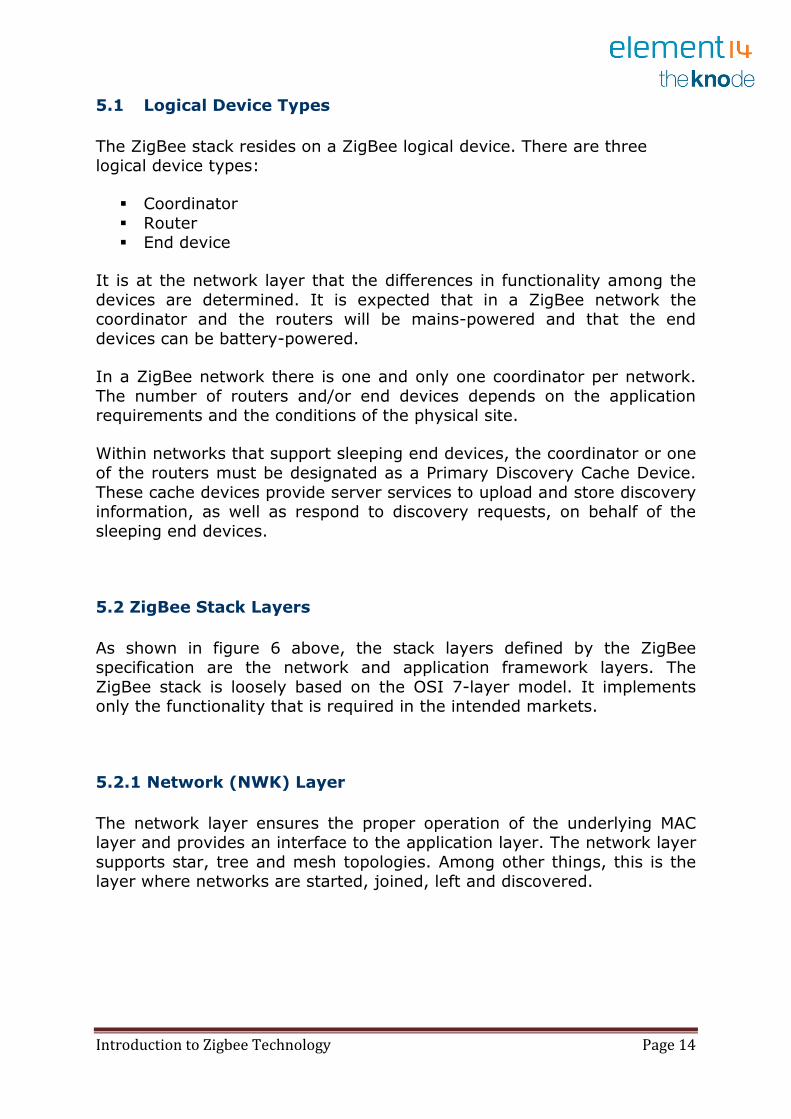
Comparison of ZigBee Devices at the Network Layer
ZigBee Network Layer Function Coordinator Router End
Device
Establish a ZigBee network .
Permit other devices to join or leave
the network . .
Assign 16-bit network addresses . .
Discover and record paths for efficient
message delivery . .
Discover and record list of one-hop
neighbors . .
Route network packets . .
Receive or send network packets . . .
Join or leave the network . . .
Enter sleep mode
.
When a coordinator attempts to establish a ZigBee network, it does an energy scan to find the best RF channel for its new network. When a channel has been chosen, the coordinator assigns the logical network
identifier, also known as the PAN ID, which will be applied to all devices that join the network.
A node can join the network either directly or through association. To join directly, the system designer must somehow add a node's extended
address into the neighbour table of a device. The direct joining device will issue an orphan scan, and the node with the matching extended address
(in its neighbour table) will respond, allowing the device to join.
To join by association, a node sends out a beacon request on a channel, repeating the beacon request on other channels until it finds an
acceptable network to join.
Introduction to Zigbee Technology Page 16
The network layer provides security for the network, ensuring both
authenticity and confidentiality of a transmission.
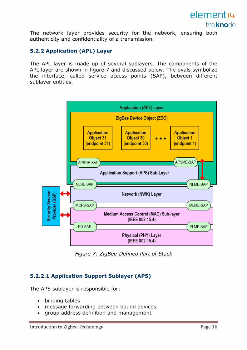
5.2.2 Application (APL) Layer
The APL layer is made up of several sublayers. The components of the
APL layer are shown in figure 7 and discussed below. The ovals symbolize the interface, called service access points (SAP), between different
sublayer entities.
Figure 7: ZigBee-Defined Part of Stack
5.2.2.1 Application Support Sublayer (APS)
The APS sublayer is responsible for:
• binding tables • message forwarding between bound devices
• group address definition and management
Introduction to Zigbee Technology Page 17
• address mapping from 64-bit extended addresses to 16-bit NWK
addresses • fragmentation and reassembly of packets
• reliable data transport
The key to interfacing devices at the need/service level is the concept of binding. Binding tables are kept by the coordinator and all routers in the
network. The binding table maps a source address and source endpoint to one or more destination addresses and endpoints. The cluster ID for a
bound set of devices will be the same.
5.2.2.2 Application Framework
The application framework is an execution environment for application objects to send and receive data. Application objects are defined by the
manufacturer of the ZigBee-enabled device. As defined by ZigBee, an application object is at the top of the application layer and is determined
by the device manufacturer. An application object actually implements the application; it can be a light bulb, a light switch, an LED, an I/O line, etc.
The application profile is run by the application objects.
Each application object is addressed through its corresponding endpoint. Endpoint numbers range from 1 to 240. Endpoint 0 is the address of the
ZigBee Device Object (ZDO). Endpoint 255 is the broadcast address, i.e.,
messages are sent to all of the endpoints on a particular node. Endpoints 241 through 254 are reserved for future use.
ZigBee defines function primitives, not an application programming
interface (API).
5.2.2.3 ZigBee Device Object (ZDO)
The ZDO is responsible for overall device management, specifically it is responsible for:
• initializing the APS sublayer and the NWK layer
• defining the operating mode of the device (i.e., coordinator, router, or end device)
• device discovery and determination of which application services the device provides
• initiating and/or responding to binding requests • security management
Device discovery can be initiated by any ZigBee device. In response to a device discovery inquiry end devices send their own IEEE or NWK address
(depending on the request). A coordinator or router will send their own IEEE or NWK address plus all of the NWK addresses of the devices
Introduction to Zigbee Technology Page 18
associated with it. (A device is associated with a coordinator or router if it
is a child node of the coordinator or router.). Device discovery allows for an ad-hoc network. It also allows for a self-healing network.
Service discovery is a process of finding out what application services are
available on each node. This information is then used in binding tables to associate a device offering a service with a device that needs that service.
5.3 ZigBee Addressing
Before joining a ZigBee network, a device with an IEEE 802.15 compliant radio has a 64-bit address. This is a globally unique number made up of
an Organizationally Unique Identifier (OUI) plus 40 bits assigned by the
manufacturer of the radio module. OUIs are obtained from IEEE to ensure global uniqueness.
When the device joins a Zigbee network, it receives a 16-bit address
called the NWK address. Either of these addresses, the 64-bit extended address or the NWK address, can be used within the PAN to communicate
with a device. The coordinator of a ZigBee network always has a NWK address of "0."
ZigBee provides a way to address the individual components on the device of a node through the use of endpoint addresses. During the
process of service discovery the node makes available its endpoint numbers and the cluster IDs associated with the endpoint numbers. If a
cluster ID has more than one attribute, the command is used to pass the attribute identifier.
5.3.1 ZigBee Messaging
After a device has joined the ZigBee network, it can send commands to other devices on the same network. There are two ways to address a
device within the ZigBee network: direct addressing and indirect
addressing.
Direct addressing requires the sending device to know three kinds of information regarding the receiving device:
1. Address
2. Endpoint Number
3. Cluster ID
Indirect addressing requires that the above three types of information be
committed to a binding table. The sending device only needs to know its own address, endpoint number and cluster ID. The binding table entry
Introduction to Zigbee Technology Page 19
supplies the destination address(es) based on the information about the
source address.
The binding table can specify more than one destination address/endpoint for a given source address/endpoint combination. When an indirect
transmission occurs, the entire binding table is searched for any entries where the source address/endpoint and cluster ID matches the values of
the transmission. Once a matching entry is found, the packet is sent to the destination address/endpoint. This is repeated for each entry where
the source endpoint/address and clusterID match the transmission values.
5.3.2 Broadcast Addressing
There are two distinct levels of broadcast addresses used in a ZigBee network. One is a broadcast packet with a MAC layer destination address
of 0xFFFF. Any transceiver that is awake will receive the packet. The packet is re-transmitted three times by each device, thus these types of
broadcasts should only be used when necessary.
The other broadcast address is the use of endpoint number 0xFF to send a message to all of the endpoints on the specified device.
5.3.3 Group Addressing
An application can assign multiple devices and specific endpoints on those
devices to a single group address. The source node would need to provide the cluster ID, profile ID and source endpoint.
5.4 ZigBee Application Profiles
What is a ZigBee profile and why would you want one? Basically a profile is a message-handling agreement between applications on different
devices. A profile describes the logical components and their interfaces. Typically, no code is associated with a profile.
The main reason for using a profile is to provide interoperability between different manufacturers. For example, with the use of the Home Lighting
profile, a consumer could use a wireless switch from one manufacturer to control the lighting fixture from another manufacturer.
There are three types of profiles: public (standard), private and
published. Public profiles are managed by the ZigBee Alliance. Private profiles are defined by ZigBee vendors for restricted use. A private profile
can become a published profile if the owner of the profile decides to publish it.
Introduction to Zigbee Technology Page 20
All profiles must have a unique profile identifier. You must contact the
ZigBee Alliance if you have created a private profile in order to be allocated a unique profile identifier.
A profile uses a common language for data exchange and a defined set of
processing actions. An application profile will specify the following:
• set of devices required in the application area
• functional description for each device • set of clusters to implement the functionality
• which clusters are required by which devices
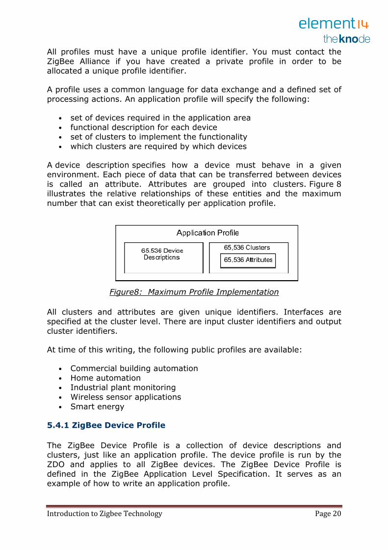
A device description specifies how a device must behave in a given environment. Each piece of data that can be transferred between devices
is called an attribute. Attributes are grouped into clusters. Figure 8 illustrates the relative relationships of these entities and the maximum
number that can exist theoretically per application profile.
Figure8: Maximum Profile Implementation
All clusters and attributes are given unique identifiers. Interfaces are specified at the cluster level. There are input cluster identifiers and output
cluster identifiers.
At time of this writing, the following public profiles are available:
• Commercial building automation
• Home automation • Industrial plant monitoring
• Wireless sensor applications
• Smart energy
5.4.1 ZigBee Device Profile
The ZigBee Device Profile is a collection of device descriptions and clusters, just like an application profile. The device profile is run by the ZDO and applies to all ZigBee devices. The ZigBee Device Profile is
defined in the ZigBee Application Level Specification. It serves as an example of how to write an application profile.
Introduction to Zigbee Technology Page 21
6. Zigbee Frame Structure
The frame structures have been designed to keep the complexity to a minimum while at the same time making them sufficiently robust for transmission on a noisy channel. Each successive protocol layer adds to
the structure with layer-specific headers and footers.
6.1 The IEEE 802.15.4 MAC defines four frame structures:
A beacon frame, used by a coordinator to transmit beacons.
A data frame, used for all transfers of data.
An acknowledgment frame, used for confirming successful frame
reception.
A MAC command frame, used for handling all MAC peer entity control transfers.
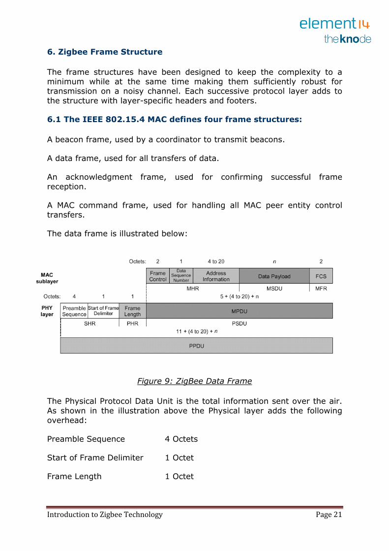
The data frame is illustrated below:
Figure 9: ZigBee Data Frame
The Physical Protocol Data Unit is the total information sent over the air.
As shown in the illustration above the Physical layer adds the following
overhead:
Preamble Sequence 4 Octets
Start of Frame Delimiter 1 Octet
Frame Length 1 Octet
Introduction to Zigbee Technology Page 22
The MAC adds the following overhead:
Frame Control 2 Octets
Data Sequence Number 1 Octet
Address Information 4 – 20 Octets
Frame Check Sequence 2 Octets
In summary the total overhead for a single packet is therefore 15 -31
octets (120 bits); depending upon the addressing scheme used (short or 64 bit addresses). Please note that these numbers do not include any
security overhead.
6.2. Super Frame Structure
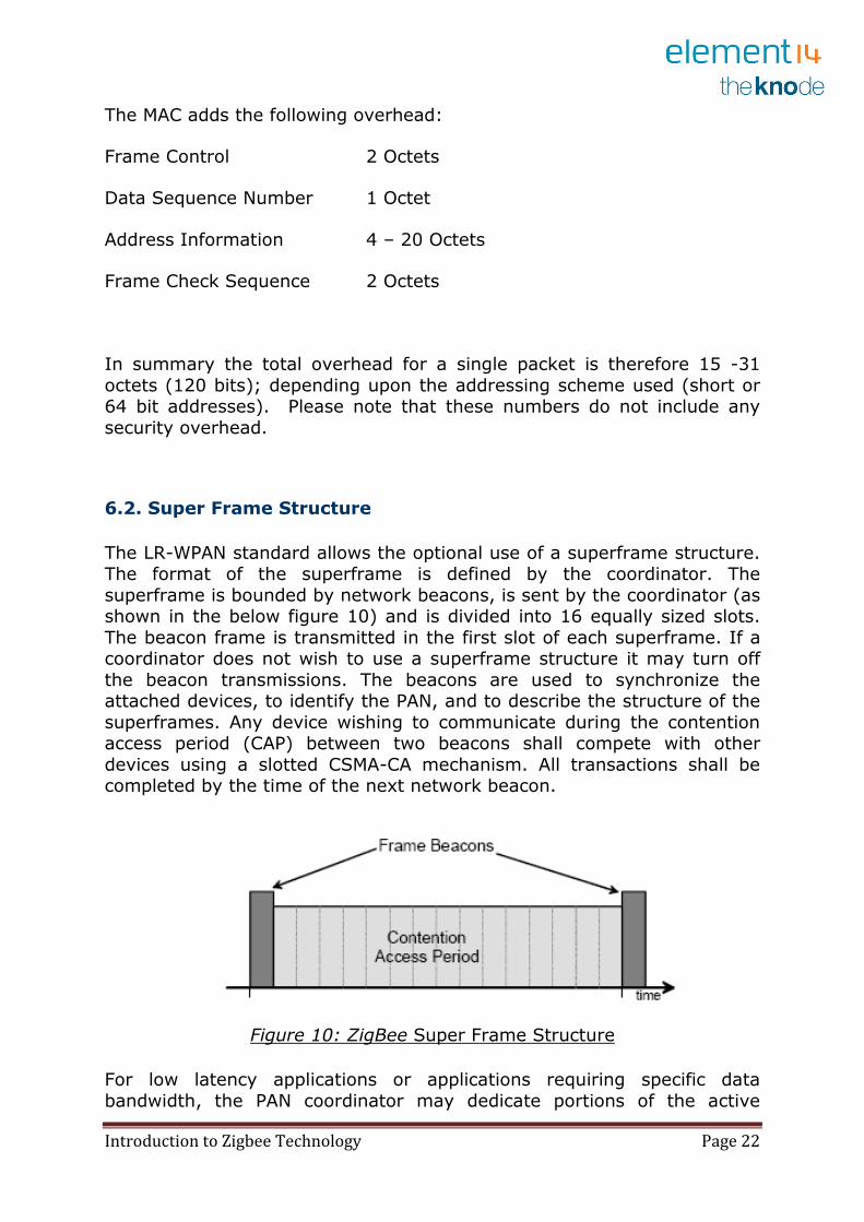
The LR-WPAN standard allows the optional use of a superframe structure. The format of the superframe is defined by the coordinator. The
superframe is bounded by network beacons, is sent by the coordinator (as shown in the below figure 10) and is divided into 16 equally sized slots.
The beacon frame is transmitted in the first slot of each superframe. If a coordinator does not wish to use a superframe structure it may turn off
the beacon transmissions. The beacons are used to synchronize the attached devices, to identify the PAN, and to describe the structure of the
superframes. Any device wishing to communicate during the contention access period (CAP) between two beacons shall compete with other
devices using a slotted CSMA-CA mechanism. All transactions shall be completed by the time of the next network beacon.
Figure 10: ZigBee Super Frame Structure
For low latency applications or applications requiring specific data
bandwidth, the PAN coordinator may dedicate portions of the active
Introduction to Zigbee Technology Page 23
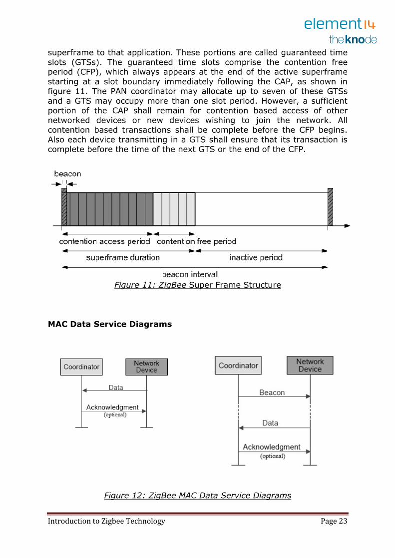
superframe to that application. These portions are called guaranteed time
slots (GTSs). The guaranteed time slots comprise the contention free period (CFP), which always appears at the end of the active superframe
starting at a slot boundary immediately following the CAP, as shown in figure 11. The PAN coordinator may allocate up to seven of these GTSs
and a GTS may occupy more than one slot period. However, a sufficient portion of the CAP shall remain for contention based access of other
networked devices or new devices wishing to join the network. All contention based transactions shall be complete before the CFP begins.
Also each device transmitting in a GTS shall ensure that its transaction is complete before the time of the next GTS or the end of the CFP.
Figure 11: ZigBee Super Frame Structure
MAC Data Service Diagrams
Figure 12: ZigBee MAC Data Service Diagrams
Introduction to Zigbee Technology Page 24
Disclaimer
The information contained in this document is for general information
purposes only. Thanks to the suppliers who provided the information and while we endeavour to keep the information up to date and correct, we
make no representations or warranties of any kind, express or implied, about the completeness, accuracy, reliability, suitability or availability
with respect to the website or the information, products, services, or
related graphics contained on the website for any purpose. Any reliance you place on such information is therefore strictly at your own
responsibility.


