117
INTRODUCTION
The purpose of this manual is to serve as a guide for railroad personnel engaged in the operation of the ELECTRO-MOTIVE 1750 HP GP9 locomotive.
The first three sections of the manual present the necessary information to enable the engine man to successfully operate the locomotive .. over the road." A general description and location of the component parts is contained in Section 1. Section 2 outlines the recommended procedures to be followed for successful operation of the locomotive equipment. A description and general operation of the most commonly used "extras," including dynamic brakes, is found at the end of Section 2. Section 3 outlines the possible causes, location, and correction of difficulties that may be encountered while "on the road."
Sections 4 and 5 of the manual nave been included for those who desire a more thorough knowledge of the locomotive's Systems and Electrical equipment. Charts and wiring diagrams are used to illustrate the descriptive material.
Principal articles of each section are numbered consecutively for ready reference, as is each page of the section. Articles and pages are numbered in the 100 series type of numbering. A page in the 400' s is in Section 4 as is any article numbered in the 400' s.
GP9-0-1256
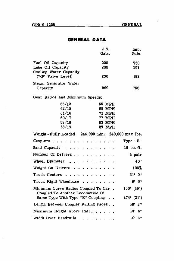
GENERAL DATA
Fuel Oil Capacity Lube Oil Capacity Cooling Water Capacity
("G" Valve Level)
Steam Generator Water Capacity
U.S. Gals.
900 200
230
900
Gear Ratios and Maximum Speeds:
65/12 62/15 61/16 60/17 59/18 58/19
55 MPH 65 MPH 71 MPH 77 MPH 83 MPH 89 MPH
GENERAL
Imp. Gals.
750 167
192
750
Weight - Fully Loaded
Couplers •....
244,000 min. - 248,000 max.lbs.
Sand Capacity
Number Of Drivers
Wheel Diameter
weight On Drivers
Truck Centers • .
Truck Rigid Wheelbase
Minimum Curve Radius Coupled To Car • Coupled To Another Locomotive Of Same Type With Type "E" Coupling ••
Length Between Coupler Pulling Faces. •
Maximum Height Above Rail. •
Width Over Handrails.
Type "E"
18 cu. ft.
4 pair
40"
100%
31' 0"
9' 0"
150' (39°)
274' (2r)
56' 2"
14' 6"
10' 3"
GP9-0-1256 GENERAL
TABLE OF CONTENTS
Page
SECTION 1 - DESCRIPTION 100
General Description 100 Diesel Engine 100 Main Generator 101 Alternator 102 Traction Motors 102
Auxiliary Equipment 103 Storage Battery 103 Auxiliary Generator 103 Traction Motor Blowers 103 Radiator Cooling Fans 104 Air Compressor 104 Fuel Pump 106
Operating Controls 106 Throttle Lever 106 Reverse Lever 107 Selector Lever 108 Mechanical Interlocks On The Controller 108
Air Brake Equipment 110 Automatic Brake Valve 113 Independent Brake Valve 113 Rotair Valve 114 Brake Pipe Cut-Out Cock 115 Safety Control Foot Pedal 116
Enginemen's Control Panel 116 Load Indicating Meter 116 Operating Circuit Breakers 117 Wheel Slip Light 118 Ground Relay 118 PC Switch And Light 118 Headlight Control Switch 118 Air Brake Gauges 120
GENERAL GP9-0-1256 Page
Electrical Control Cabinet 120 Isolation Switch 120 Engine Start And Stop Buttons 121 Fuses, Knife Switches And Circuit Breakers 121 Ground Relay 123 Control Air Pressure Regulator 123 Alarm Indications 124 Emergency Fuel Cut-Off Ring 124
Engine Room 125 Engine GO,vernor 126 Load Regulator 127 Engine Overspeed Trip 128 Manual Layshaft Lever 128
Miscellaneous Equipment 129 Speed Recorder 129 Hand Brake 129 Manual Sanding Valve 129 Classification Lights 130 Horn Valves 130 Bell Ringer 130 Windshield Wipers 130 Cab Heaters And Defrosters 131 Trucks 132
SECTION 2 - OPERATION 200
Basic Information 200 When Boarding The Locomotive 200 Precautions Before Starting Engine 203 To Start Engine 205 Placing An Engine On The Line 206 To Stop Engine 206 Securing Locomotive For Layover 208
Handling Locomotive 208 Precautions Before Moving Locomotive 208 Handling Light Locomotive 209 Coupling To Train And Pumping Up Air 209
GP9-0-1256 GENERAL Page
Starting A Train 209 Automatic Sanding In Power 212 Acceleration Of A Train 213 Slowing Down Because Of A Grade 213 Locomotive Operation At Very Slow Speeds 213
Braking 214 Air Braking With Power 214
Miscellaneous Operating Instructions 214 Multiple Unit Operation 214 Uncoupling And Coupling Units In Locomotive 215 Changing Operating Ends 215 Handling Locomotive Dead-In-Train 218 Doubleheading 220 Operation In Helper Service 220 Freezing Weather Precautions 220 Operation Over Railroad Crossings 222 Running Through Water 222 Resetting PC Switch After Safety
Control Application 222 Ground Relay Action 222 Wheel Slip Indication 223 Indication Of A Pair Of Wheels Sliding 223 Air Box Drains 224
Operation Of Locomotive "Extras" 224 Dynamic Brake Operation 224 Dynamic Brake Selector Switch 228 Dynamic Brake Warning Light 229 Dynamic Brake Grid Blower 229 Dynamic Brake Wheel Speed Control 229 Hump Speed Control 230 Motor Lock-Out Switches 233 Dual Cab Control Operation 233 Brake Pipe Flow Indicator 235
SECTION 3 - LOCATION AND CORRECTION OF DIFFICULTIES ON-THE-ROAD 300
General 301
GENERAL GP9-0-1256 Page
If Alarm Bells Ring 302
Additional Safety Devices 307 "PC" Switch Open 307 Engine Overspeed Trip 307 Fuel Flow 308 Emergency Fuel Oil Cutoff Valve 308 Control Air Pressure 309
Correction Of Difficulties 309 If The Engine Goes To Idle 309 If The Engine Stops 309 How To Start Engine 310 If The Engine Does Not Rotate
When "Start" Button Is Pressed 310 If The Engine Rotates But Does Not
Start When "Start" Button Is Pressed 310 If The Engine Does Not Speed Up
When Throttle Is Opened 311 Engine Speeds Up But Locomotive Does
Not Move When Throttle Is Opened 311 Battery A mmeter Shows Continual Discharge 311 Compressor Control 311 Cylinder Test Valves 312
Trouble Shooting Check Chart 313
SECTION 4 - COOLING, LUBRICATING OIL, FUEL OIL AND Am SYSTEMS 400
Cooling System 400 Operating Water Level 403 Filling Cooling System 403 Draining Cooling System 404 Cab Heating And Ventilating 404 Engine Room Winterization 406
Lubricating Oil System 407 Oil Level 408 Adding Oil To System 408 Oil Pressure 409
GP9-0-1256 GENERAL Page
Fuel Oil System 409 Fuel Sight Glasses 411 Filling Fuel Tanks 412 Fuel Gauge 412 Emergency Fuel Cutoff Valve 413
Air System 413 Air Compressor 414 Compressor Control 415 Manual Unloader Valve 418 Draining Of Air System 419
SECTION 5 - ELECTRICAL EQUIPMENT 500
Basic Electrical Systems 500 Main Generator 501 Traction Motors 502 Reversing Locomotive 503 Transition 503 Transition Control Circuit 506 Load Regulator 515 Engine Speed Control 517 Engine Relay - ER 519 Battery Field Contactor And Fuse - BF 519 Wheel Slip Control System 520 Battery Switch 522 Battery Ammeter 523 Reverse Current Relay - RCR 523 Battery Changing Contactor - Be 523 Ground Relay - GR 523 Voltage Regulator 525 Auxiliary Generator Fuse 525 Auxiliary Generator Field Circuit Breaker 525 Alternator Field Circuit Breaker 526 No AC Voltage Relay - NVR 526
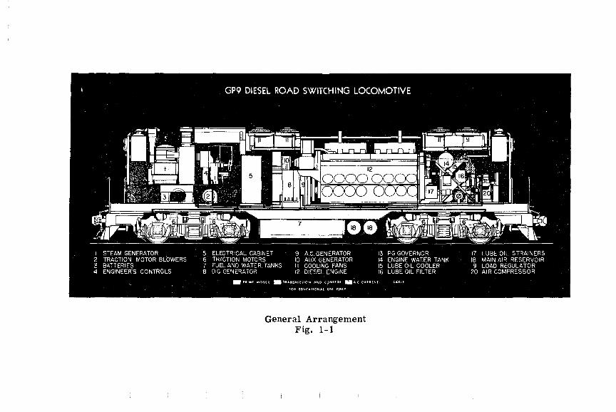
General Arrangement Fig. 1-1
GP9-1-154 DESCRIPTION
SECTION 1 DESCRIPTION
GENERAL DESCRIPTION
A description and general location of equipment on the GP9 locomotive is given in this section.
A locomotive consists of one or more units rated at 1750 horsepower per unit. In multiple unit operation, the locomotive is operated and controlled from the engineman's control stand in the lead unit.
Basically, the short hood end of the GP9 is the front end of the unit and the long hood end is the rear end of the unit. In multiple unit operation, the units can be coupled together from either end.
Two types of brake equipment are used. To differentiate between the two types, the model designations "GP9L" and "GP9R" are used. The GP9L is equipped with 6BL brake equipment while the GP9R is equipped with 24RL brake equipment.
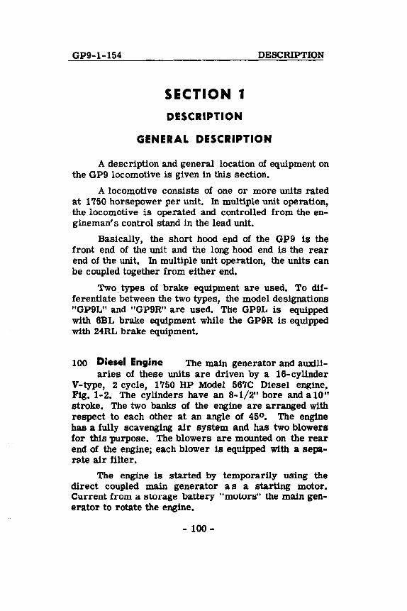
100 Diesel Engine The main generator and auxili-aries of these units are driven by a l6-cylinder
V-type, 2 cycle, 1750 HP Model 567C Diesel engine, Fig. 1-2. The cylinders have an 8-1/2" bore and a 10" stroke. The two banks of the engine are arranged with respect to each other at an angle of 450 • The engine has a fully scavenging air system and has two blowers for this purpose. The blowers are mounted on the rear end of the engine; each blower Is equipped with a separllte air filter.
The engine is started by temporarily using the direct coupled main generator a s a starting motor. Current from a storage battery "motors" the main generator to rotate the engine.
- 100-
DESCRIPTION GP9-1-154
NOTE: In this manual, the word "engine" refers specifically to the Diesel engine; the word "locomotive" refers to a consist of one or more units.
Front Three-Quarter View 567C Engine Fig. 1-2
Main Generator and Alternator
Fig. 1-3
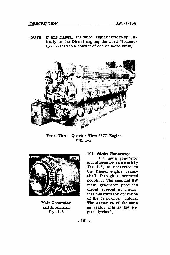
101 Main Generator The main generator
and alternator ass c m b I Y Fig. 1-3, is connected to the Diesel engine crankshaft through a serrated coupling. The constant KW main generator produces direct current at a nominal 600 volts for operation of the traction motors. The armature of the main generator acts as the engine flywheel.
- 101 -
GP9-1-156 DESCRIPTION
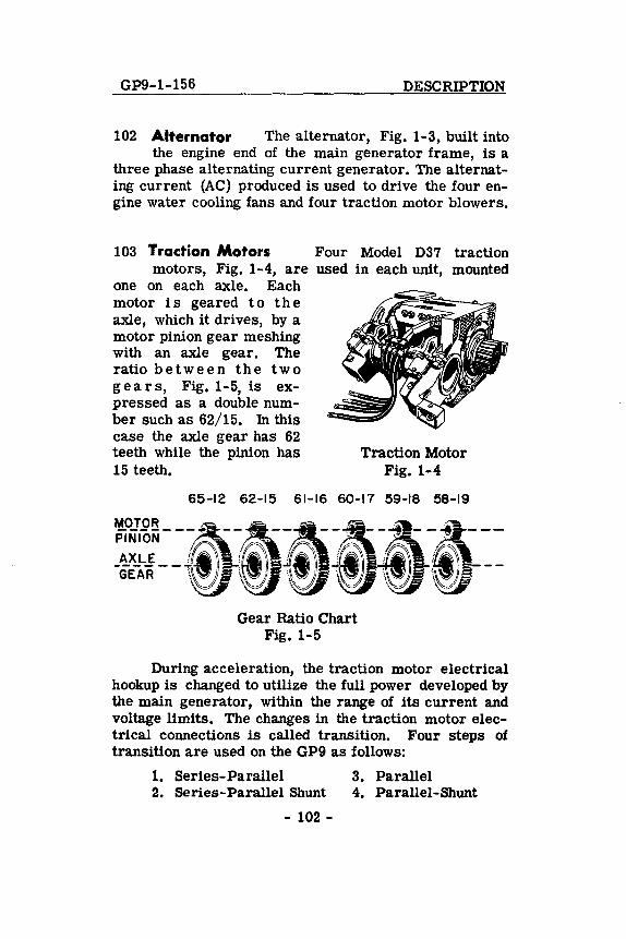
102 Alternator The alternator, Fig. 1-3, built into the engine end of the main generator frame, is a
three phase alternating current generator. The alternating current (AC) produced is used to drive the four engine water cooling fans and four traction motor blowers.
103 Traction Motors Four Model D37 traction motors, Fig. 1-4, are used in each unit, mounted
one on each axle. Each motor is geared to the axle, which it drives, by a motor pinion gear meshing with an axle gear. The ratio bet wee nth e two g ear s, Fig. 1-5, is expressed as a double number such as 62/15. In this case the axle gear has 62 teeth while the pinion has 15 teeth.
Traction Motor Fig. 1-4
65-12 62-15 61-16 60-17 59-18 58-19
Gear Ratio Chart Fig. 1-5
During acceleration, the traction motor electrical hookup is changed to utilize the full power developed by the main generator, within the range of its current and voltage limits. The changes in the traction motor electrical connections is called transition. Four steps 01 transition are used on the GP9 as follows:
1. Series-Parallel 3. Parallel 2. Series-Parallel Shunt 4. Parallel-Shunt
- 102 -
DESCRIPTION GP9-1-154
The changing of the traction motor electrical connections or transition is completely automatic during locomotive acceleration or deceleration on GP9 locomotives. There is no provision for effecting manual transition on a GP9 locomotive or for forestalling the automatic transition.
AUXILIARY EQUIPMENT
104 Storage Battery Power from a 32 cell 64 volt storage battery is used to start the Diesel engine.
The storage battery compartment is accessible through hinged door sections in the "raised pattern" walk adjacent to the cab on each side of the short hood end of the unit. With the Diesel engine running, the auxiliary generator charges the storage battery.
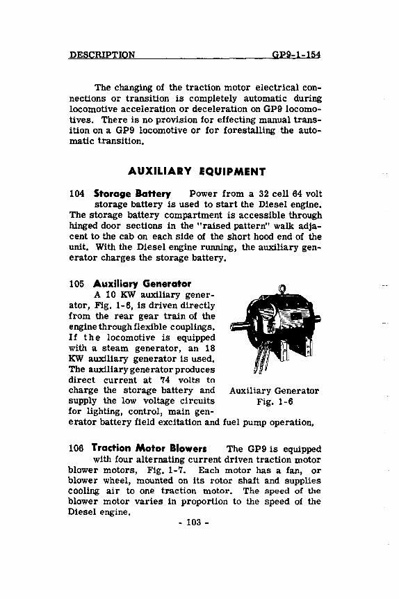
105 Auxiliary Generator A 10 KW auxiliary gener
ator, Fig. 1-6, is driven directly from the rear gear train of the engine through flexible couplings. If the locomotive is equipped with a steam generator, an 18 KW auxiliary generator is used. The auxiliary generator produces direct current at 74 volts to charge the storage battery and Auxiliary Generator supply the low voltage circuits Fig. 1-6 for lighting, control, main gen-erator battery field excitation and fuel pump operation.
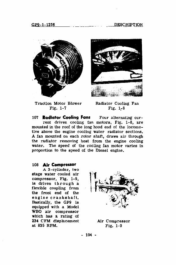
106 Traction Motor Blowers The GP9 is equipped with four alternating current driven traction motor
blower motors, Fig. 1-7. Each motor has a fan, or blower wheel, mounted on its rotor shaft and supplies cooling air to one traction motor. The speed of the blower motor varies in proportion to the speed of the Diesel engine.
- 103 -
GP9-1-1256
Traction Motor Blower Fig. 1-7
DESCRIPTION
Radiator Cooling Fan Fig. 1;-8
107 Radiator Cooling Fans Four alternating cur-rent driven cooling fan motors, Fig. 1-8, are
mounted in the roof of the long hood end of the locomotive above the engine cooling water radiator sections. A fan mounted on each rotor shaft, draws air through the radiator removing heat from the engine cooling water. The speed of the cooling fan motor varies in proportion to the speed of the Diesel engine.
108 Air Compressor A 3-cylinder, two
stage water cooled air compressor, Fig. 1-9, is driven t h r 0 ugh a flexible coupling from the front end of the eng i n e c ran k s h a ft. Basically, the GP9 is equipped with a Model WBO air compressor whIch has a rating of 234 CFM displacement at 835 RPM.
- 104 -
Air Compressor Fig. 1-9
DESCRIPTION GP9-1-1256
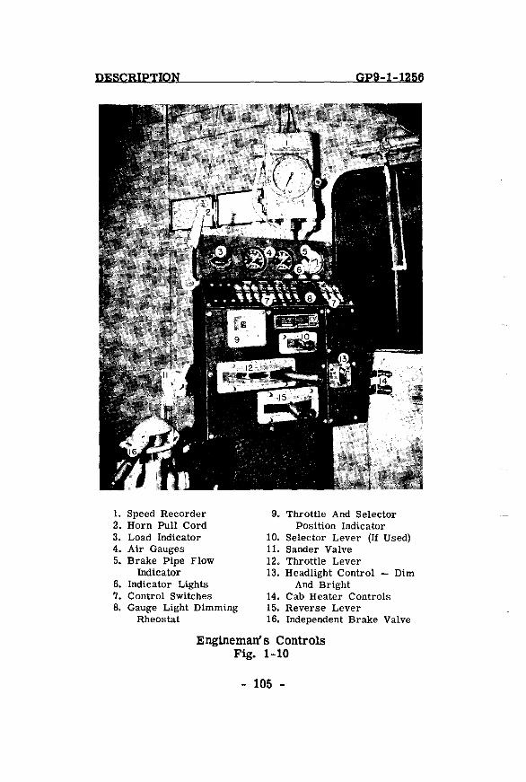
1. 2. 3. 4. 5.
6. 7. 8.
Speed Recorder 9. Throttle And Selector Horn Pull Cord Position Indicator Load Indicator 10. Selector Lever (If Used) Air Gauges 11. Sander Valve Brake Pipe Flow 12. Throttle Lever
Indicator 13. Headlight Control - Dim Indicator Lights And Bright Control Switches 14. Cab Heater Controls Gauge Light Dimming 15. Reverse Lever
Rheostat 16. Independent Brake Valve
Engineman's Controls Fig. 1-10
- 105 -
GP9-1-1256 DESCRIPTION
109 Fuel Pump The fuelpump is driven by a sepa-rate direct current electric motor through a flexi
ble coupling. The pump assembly is mounted on the equipment rack which supports the engine cooling water tank. To operate the fuel pump, the 30 ampere "Fuel Pump" circuit breaker in the electrical cabinet must be "ON" and the"Control and Fuel Pump"circuit breaker on the engineman's control panel must be "ON."
OPERATING CONTROLS
Three levers and two brake valve handles control the entire operation of the locomotive. These are the throttle, reverse and selector levers, mounted in the controller, and the independent and automatic brake valve handles. See Fig. 1-10.
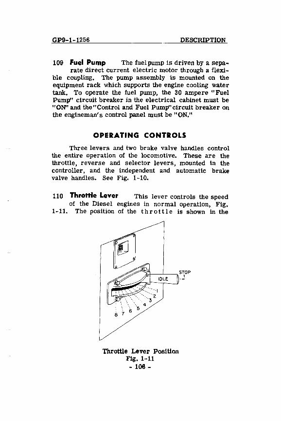
110 ThroHle Lever This lever controls the speed of the Diesel engines in normal operation, Fig.
1-11. The position of the t h rot tl e is shown in the
A:tt--~---. S"\OP
Throttle Lever Position Fig. 1-11
- 106-
--'
DESCRIPTION GP9-1-1256
illuminated indicator in the upper left hand corner of the controller. The throttle has ten positions, Stop, Idle and running speeds 1 to 8. Stop can be obtained by pulling the throttle lever out away from the controller and pushing it one step beyond idle position; this stops all engines. Idle position is as far forward as the throttle lever can be moved without pulling it toward the engine man. Each running notch on the throttle increases the engine speed in 80 RPM increments from 275 RPM at idle and Run 1, to 835 RPM at full throttle. The throttle may be closed completely with one motion in an emergency, but should be closed one notch at a time in normal operation. It may be opened as rapidly as desired PROVIDING OPERATING CONDITIONS AND TRAIN CONSIST PERMITS. This arrangement is of special value in "kicking" cars and while operating over the road on a "tight" schedule.
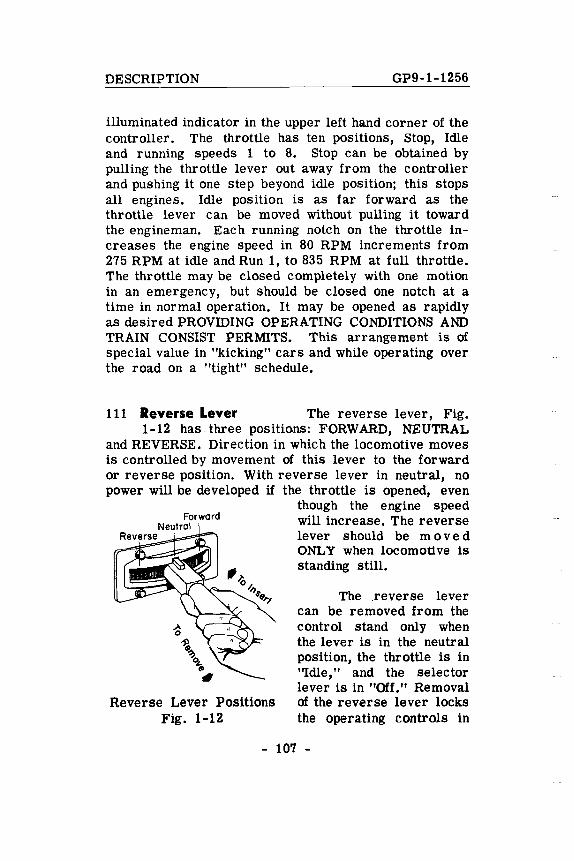
111 Reverse Lever The reverse lever, Fig. 1-12 has three positions: FORWARD, NEUTRAL
and REVERSE. Direction in which the locomotive moves is controlled by movement of this lever to the forward or reverse position. With reverse lever in neutral, no power will be developed if the throttle is opened, even
Reverse Lever Positions Fig. 1-12
though the engine speed will increase. The reverse lever should be m 0 v e d ONL Y when locomotive is standing still.
The reverse lever can be removed from the control stand only when the lever is in the neutral position, the throttle is in ''Idle,'' and the selector lever is in "Off." Removal of the reverse lever locks the operating controls in
- 107 -
GP9-1-1256 DESCRIPTION
the controller. Remove the reverse lever from all non-operating control stands.
112 Selector Lever All GP9 locomotives are bas-ically equipped with automatic transition. Transi
tion is FULLY AUTOMATIC, both forward and backward, and no provision is made basically for making transition manually. However, a selector lever is applied to all Gpg locomotives equipped with 24 RL brake equipment. The selector lever is applied to GP9 locomotives having 6 BL brake equipment only when the locomotive is equipped with dYilamic brakes or for special multiple unit operations. The selector lever is used to control dynamic brake operation and/or to effect manual transition on any units coupled to the GP9 locomotive not equipped with automatic transition.
The pOSition of the lever is indicated by the lower indicating band illuminated through the opening at the upper left corner of . the controller front panel. The lever is spring loaded so that movement all the way in one direction will index the selector cam one notch only in that direction. It must be allowed to return to center position before indexing again in either direction.
When the selector is put in the braking "B" position, a mechanical arrangement lifts the throttle cam drum vertically to disengage the power switches and engage the braking switches. In this pOSition the throttle handle moves freely (without notching) to control a 500 ohm braking rheostat. (See Art. 229 for dynamic brake operation.)
113 Mechanical Interlocks on the Controller The levers on the control stand are interlocked so that:
1. Reverse lever in neutral.
a. Throttle nlay be nloved to any po5ition.
b. Selector may be moved between OFF and 1 (or the 1-4 range if used).
- 108 -
DESCRIPTION GP9-1-1256
2. Reverse lever in FORWARD or REVERSE.
a. Throttle may be moved to any position. b. Selector may be moved to any position.
3. Throttle in IDLE or STOP.
a. Reverse lever may be moved to any position. b. Selector may be moved to any position.
4. Throttle above IDLE.
a. Reverse lever position cannot be changed. b. Selector cannot be moved out of B to OFF
or from power to OFF.
5. Selector in OFF.
a. Reverse lever may be moved in any position. b. Throttle may be moved between IDLE and
STOP only.
6. Selector in 1 (also 2, 3 and 4 when used).
a. Reverse lever may be moved to any position. b. Throttle may be moved to any position.
7. Selector in "B".
a. Reverse lever cannot be moved. b. Throttle may be moved to any position.
Where positions 2, 3 and 4 for manual transition are incorporated in the selector, this handle may be moved from 1 to these positions if the reverse lever is in FORWARD or REVERSE, and with the throttle in any position. Permissible movement of the throttle and reverse levers with the selector in 2, 3, or 4 is the same as with the selector in 1.
- 109 -
GP9-1-1256
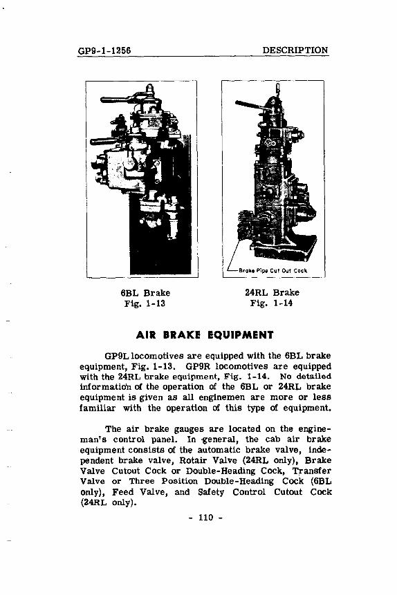
6BL Brake Fig. 1-13
DESCRIPTION
24RL Brake Fig. 1-14
AIR BRAKE EQUIPMENT
GP9L locomotives are equipped with the 6BL brake equipment, Fig. 1-13. GP9R locomotives are equipped with the 24RL brake equipment, Fig. 1-14. No detailed informatio'n of the operation of the 6BL or 24RL brake equipment is given as all engine men are more or less familiar with the operation of this type of equipment.
The air brake gauges are located on the engineman's control panel. In 'general, the cab air brake equipment consists of the automatic brake valve, independent brake valve, Rotair Valve (24RL only), Brake Valve Cutout Cock or Double-Heading Cock, Transfer Valve or Three Position Double-Heading Cock (6BL only), Feed Valve, and Safety Control Cutout Cock (24RL only).
- 110 -
DESCRIPTION GP9-1-154
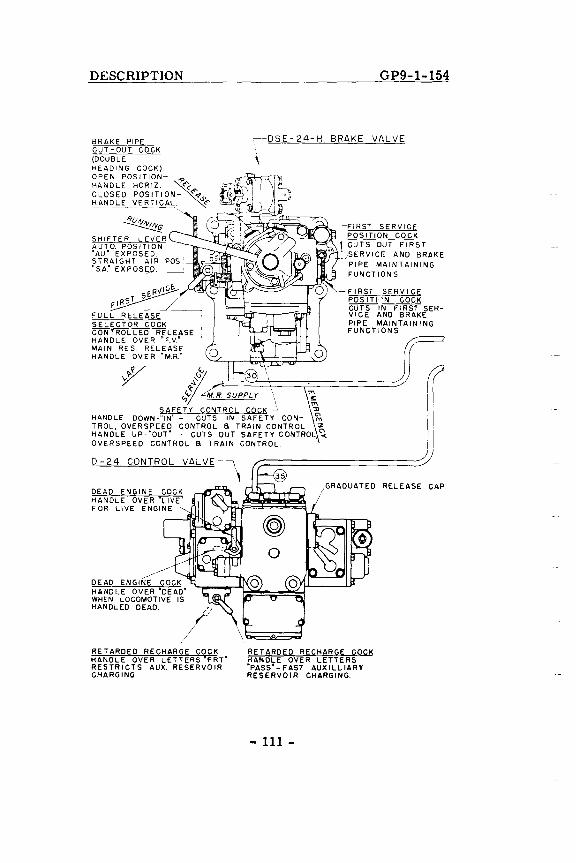
BRAKE PIPE ~-DSE-24-H BRAKE VALVE CUT-OUT COCK (DOUBLE HEADING COCK) OPEN POSITION- -5>
HANDLE HORIZ. ~<: CLOSED, POSITION,- <"",,-5' ~ND~E_VEBJICAL. <"
~ SHIFTER LEVER AUTO. POSITION "AU" EXPOSED. STRAIGHT AIR POS' "SA." EXPOSE_D_. __ _
_'1~ ~~
fULL RELEASE SELECTOR COCK CONTROLLED RELEASE HANDLE OVER "F. V." MAIN RES RELEASE HANDLE OVER "M.R."
~<.., 30
:,.' .
.,<",'1:: ~M R SUPPLY ", l~ SAFETY CONTROL COCK-- ~
HANDLE DOWN-"IN" CUTS IN SAFETY CON- ~ TROL, OVERSPEED CONTROL S TRAIN CONTROL ~ HANDLE UP·"OUT" - CUTS OUT SAFETY CONTROL -< OVERS PEED CONTROL S TRAIN CONTROL
9-24 CONTROL VALVE -'\ ,
I~:;SSI~I;NER~~~S I CUTS OUT FIRST .~,SERVICE AND BRAKE
PIPE MAINTAINING FUNCT ION S
FIRST g:~ PDSITI'N COCK CUTS IN FIRST SERVICE AND BRAKE PIPE MAINTAINING FUNCTIONS
GRADUATED RELEASE CAP
//,' RETARDED RECHARGE COCK HANDLE OVER LETTERS'FRT" RESTRICTS AUX. RESERVOIR CHARGING.
RETARDED RECHARGE COCK HANDLE OVER LETTERS "PASS"-FAST AUXILLIARY RESERVOIR CHARGING.
- 111 -
GP9-1-154
K-2-A ROTA1R
VALVE-7
L
DESCRIPTION
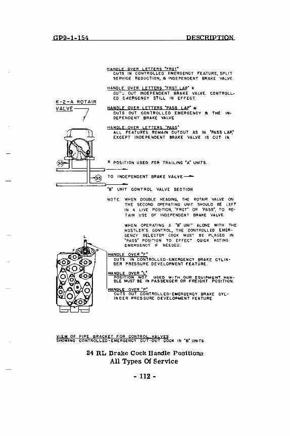
HANDLE OVER LETTERS -fRGT-CUTS IN CONTROLLED EMERGENCY FEATURE, SPLIT SERVICE REDUCTION, a INDEPENDENT BRAKE VALVE.
HANDLE OVER LETTERS "FRGT LAP" * CU'~ OUT INDEPENDENT BRAKE VALVE. CONTROLLED E,~ERGENCY STILL IN EFFECT.
HANPLE OYER LETTERS "PASS LAP' * CUTS OUT CONTROLLED EMERGENCY a THE INDEPENDENT BRAKE VALVE.
HANPLE OVER LE TIERS "pASS" ALL FEATURES REMAIN CUTOUT AS IN "PASS LAP," EXCEPT INDEPENDENT BRAKE VALVE IS CUT IN.
* POSITION USED FOR TRAILING "A" UNITS.
TO INDEPENDENT BRAKE VALVE-
"B" UNIT CONTROL VALVE SECTION.
NOTE: WHEN DOUBLE HEADING, THE ROTAIR VALVE ON THE SECOND OPERATING UNIT SHOULD BE LEFT IN A LIVE POS.lTlON, "FRGT" OR "PASS", TO RETAIN USE OF INDEPENDENT BRAKE VALVE.
WHEN OPERATING A "B" UNIT ALONE WITH THE HOSTLER'S CONTROL, THE CONTROLLED EMERGENCY SELECTOR COCK MUST BE PLACED IN "PASS" POSITION TO EFFECT QUICK ·ACTING EMERGENCY IF NEEDED.
HANDLE OVER "F" CUTS IN CONTROLLED-EMERGENCY BRAKE CYLINDER PRESSURE DEVELOPMENT FEATURE.
HANDLE OVER "L" POSITION NOT USED WI TH OUR EOUIPMENT. HANDLE MUST BE IN PASSENGER OR FREIGHT POSITION.
HANDLE OVER "p" CUTS OUT CONTROLLED-EMERGENCY BRAKE CYLINDER PRESSURE DEVELOPMENT FEATURE.
VIEW OF PIPE BRACKET FOR CONTROL VALVES SHOWING CONTROLLED-EMERGENCY CUT-OUT COCK IN "B" UNITS
24 RL Brake Cock Handle POGitionG All Types Of Service
- 112-
DESCRIPTION GP9-1-154
114 Automatic Brake Valve The automatic brake valve handle has six positions: Release, Running,
Holding (6BL) or First Service (24RL), Lap, Service and Emergency.
In multiple unit operation, with 6BL brake equipment, the automatic brake valve handle in all trailing units MUST be kept in the Lap position. If the brake valve handle is removable, it must be removed from the brake stand in the Lap position in the trailing units.
The automatic brake valve handle (rigid or hinged handle) of the 24RL brake equipment is removable in the running position. In multiple unit operation, this brake valve handle should be removed in Running position from all non-operating control stands.
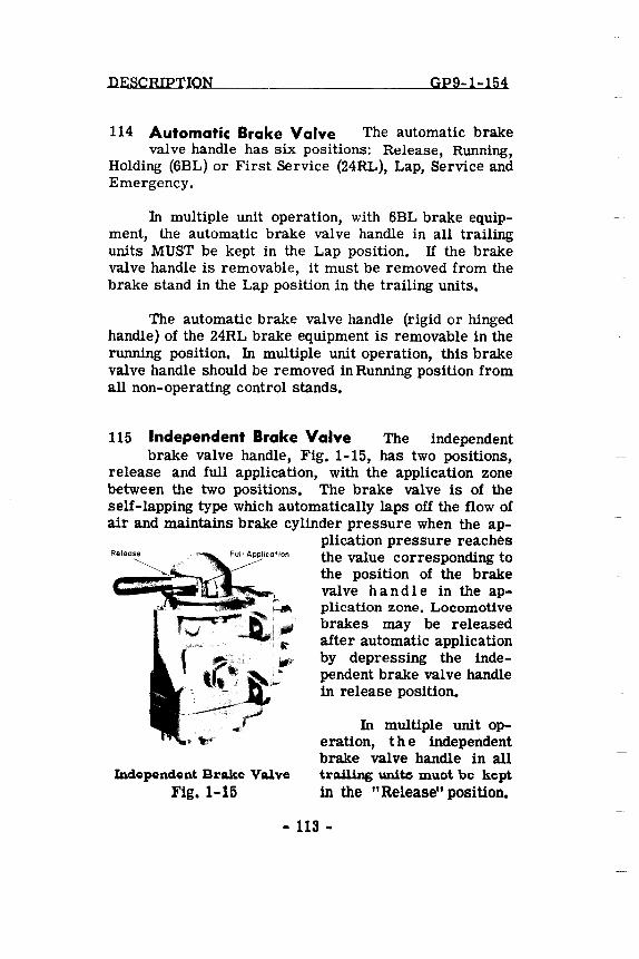
115 Independent Brake Valve The independent brake valve handle, Fig. 1-15, has two positions,
release and full application, with the application zone between the two positions. The brake valve is of the self-lapping type which automatically laps off the flow of air and maintains brake cylinder pressure when the ap
Release
Incle~nclent Brake Valve Fig. 1-15
plication pressure reaches the value corresponding to the position of the brake valve han die in the application zone. Locomotive brakes may be released after automatic application by depressing the independent brake valve handle in release position.
In multiple unit operation, the independent brake valve handle in all trailing unite muet be kept in the "Release" position.
- 113 -
GP9-1-154 DESCRIPTION
If the brake valve handle is removable, remove handle from brake valve in "Release" position.
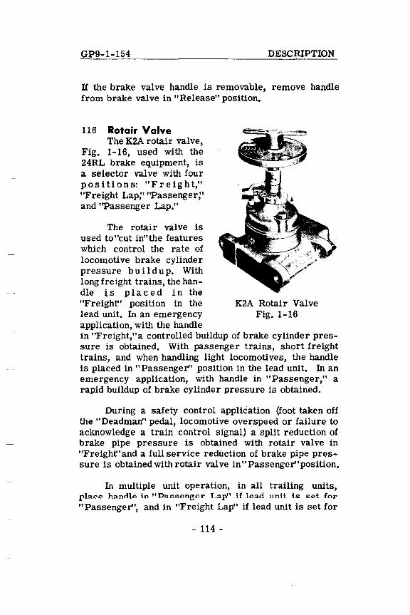
116 Rotair Valve The K2A rotair valve,
Fig. 1-16, used with the 24RL brake equipment, is a selector valve with four positions: "Freight," "Freight Lap;' "Passenger;' and ''Passenger Lap."
The rotair valve is used to"cut in"the features which control the rate of locomotive brake cylinder pressure b u i I d u p. With long freight trains, the handle ~ s p I ace din the "Freight" position in the lead unit. In an emergency application, with the handle
K2A Rotair Valve Fig. 1-16
in "Freight,"a controlled buildup of brake cylinder pressure is obtained. With passenger trains, short freight trains, and when handling light locomotives, the handle is placed in "Passenger" pOSition in the lead unit. In an emergency application, with handle in "Passenger," a rapid buildup of brake cylinder pressure is obtained.
During a safety control application (foot taken off the "Deadman" pedal, locomotive overspeed or failure to acknowledge a train control signal) a split reduction of brake pipe pressure is obtained with rotair valve in "Freight"and a full service reduction of brake pipe pressure is obtained with rotair valve in" Passenger" pOSition.
In multiple unit operation, in all trailing units, pla.ce ha.ndle in "Pa.ssenger La.p" if lea.d unit is set for
"Passenger", and in "Freight Lap" if lead unit is set for
- 114 -
DESCRIPTION GP9-1-154
"Freight". In either "Lap" position the controlled emergency feature is under control of the engineman operating the brakes from the lead unit. The "Lap" position of the rotair valve also cuts out the independent brake valves in all trailing units, obtaining full control over the locomotive brakes from the lead unit.
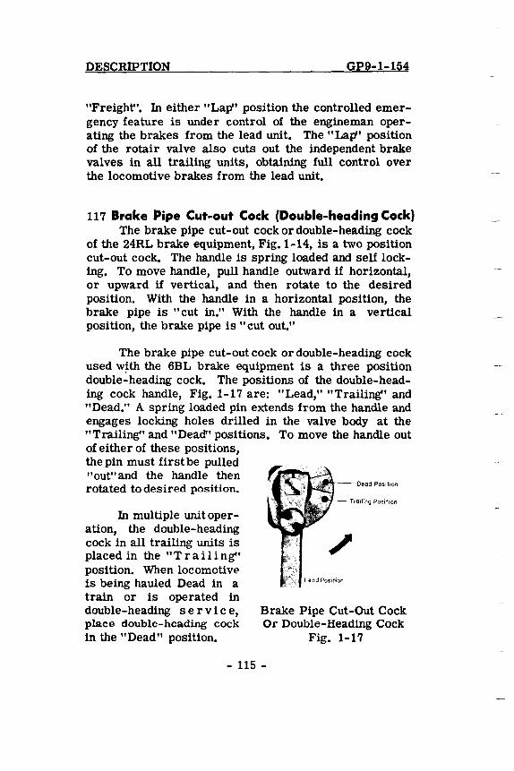
117 Brake Pipe Cut-out Cock (Double-heading Cock) The brake pipe cut-out cock or double-heading cock
of the 24RL brake equipment, Fig. 1-14, is a two position cut-out cock. The handle is spring loaded and self locking. To move handle, pull handle outward if horizontal, or upward if vertical, and then rotate to the desired position. With the handle in a horizontal position, the brake pipe is "cut in." With the handle in a vertical position, the brake pipe is" cut out."
The brake pipe cut-out cock or double-heading cock used w~th the 6BL brake equipment is a three position double-heading cock. The positions of the double-heading cock handle, Fig. 1-17 are: "Lead," "Trailing" and "Dead." A spring loaded pin extends from the handle and engages locking holes drilled in the valve body at the "Trailing" and "Dead" pOSitions. To move the handle out of either of these positions, the pin must first be pulled "out" and the handle then rotated to desired position.
In multiple unit operation, the double-heading cock in all trailing units is placed in the "Trailing" position. When locomotive is being hauled Dead in a train or is operated in double-heading s e r vic e, place double-heading cock in the "Dead" position.
,,-o----Dead Position
Brake Pipe Cut-Out Cock Or Double-Heading Cock
Fig. 1-17
- 115 -
DESCRIPTION GP9-1-1256
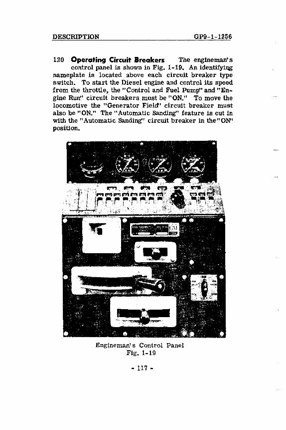
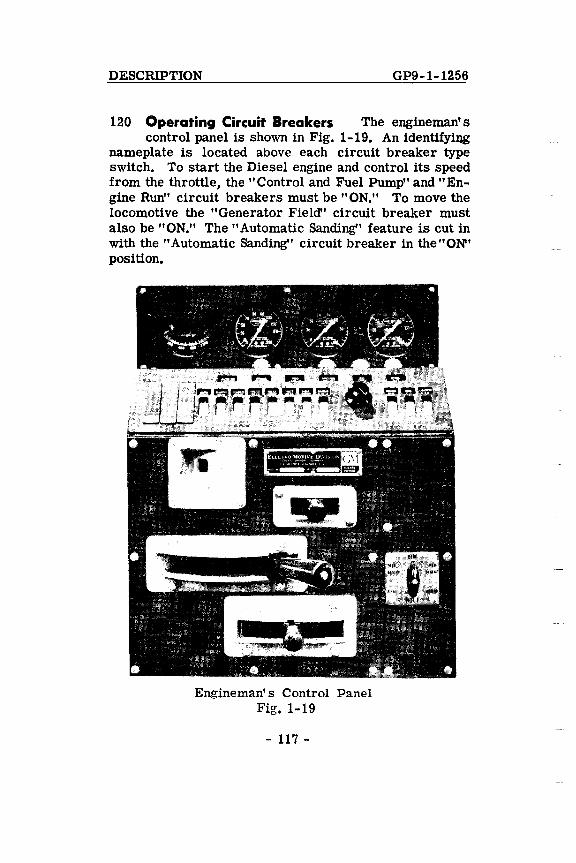
120 Operating Circuit Breakers The engineman's control panel is shown in Fig. 1-19. An identifyillg
nameplate is located above each circuit breaker type switch. To start the Diesel engine and control its speed from the throttle, the "Control and Fuel Pump" and "Engine Run" circuit breakers must be "ON." To move the locomotive the "Generator Field" circuit breaker must also be "ON." The "Automatic Sanding" feature is cut in with the "Automatic Sanding" circuit breaker in the"ON" position.
Engineman's Control Panel Fig. 1-19
- 117 -
GP9-1-1256 DESCRIPTION
118 Safety Control Foot Pedal The safety control foot pedal (if used) is located in front of the engine
man's seat. On locomotives equipped with the 24RL brake valve, having the hinged automatic brake valve handle, the handle provides an alternate control when it is depressed sufficiently to just contact the sanding bail. Either the pedal or the automatic brake valve handle must be kept depressed at all times except when the locomotive is stopped and the locomotive brakes are applied (30 pounds or more brake cylinder pressure). If both the foot pedal and the automatic brake valve are released, a penalty application of the brakes will result.
ENGINEMAN'S CONTROL PANEL
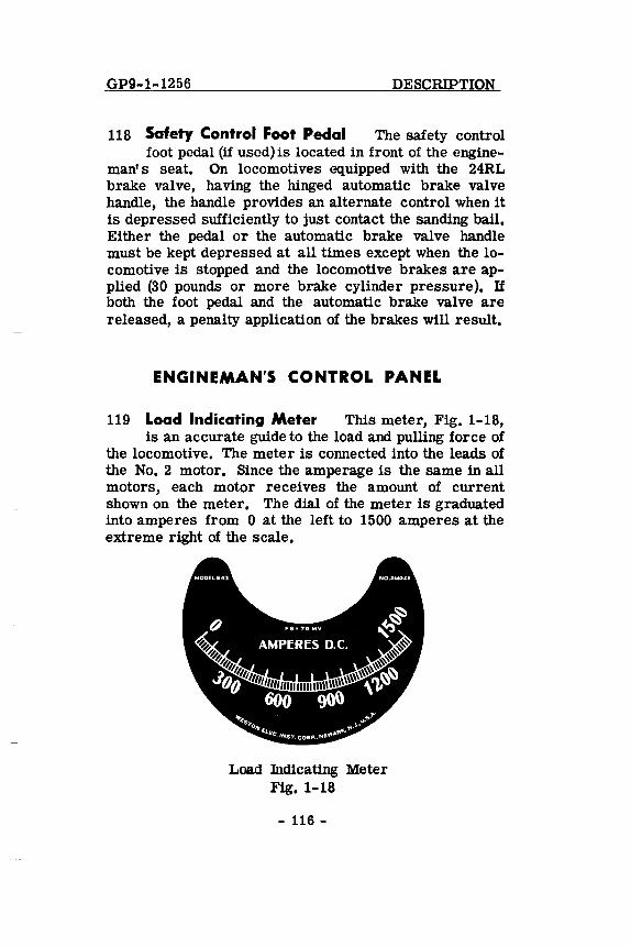
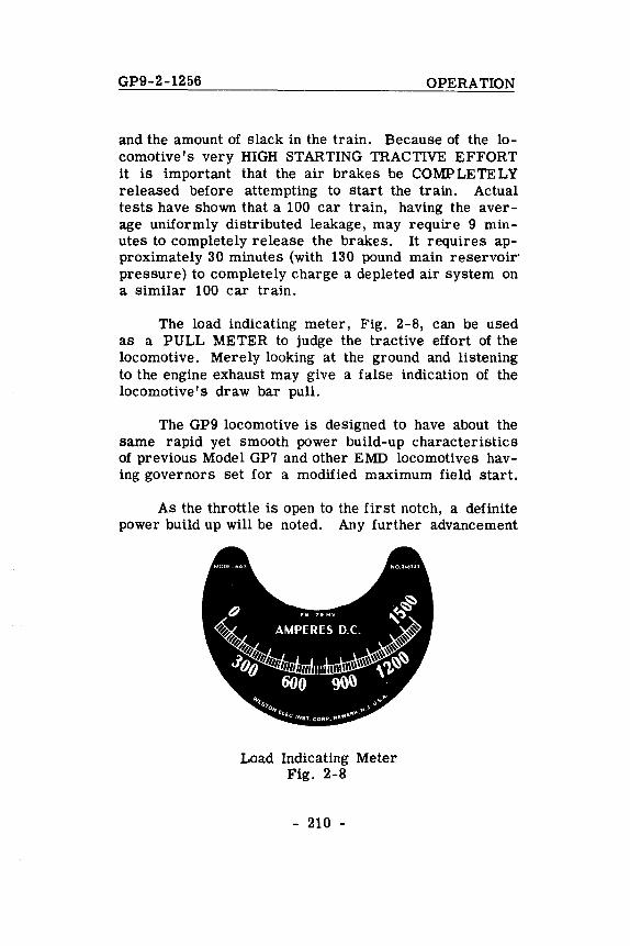
119 Load Indicating Meter This meter, Fig. 1-18, is an accurate guide to the load and pulling force of
the locomotive. The meter is connected into the leads of the No. 2 motor. Since the amperage is the same in all motors, each motor receives the amount of current shown on the meter. The dial of the meter is graduated into amperes from 0 at the left to 1500 amperes at the extreme right of the scale.
Load Indicating Meter Fig. 1-18
- 116 -
DESCRIPTION GP9-1-1256
120 Operating Circuit Breakers The engineman's control panel is shown in Fig. 1-19. An identifyiIlg
nameplate is located above each circuit breaker type switch. To start the Diesel engine and control its speed from the throttle, the "Control and Fuel Pump" and "Engine Run" circuit breakers must be "ON." To move the locomotive the "Generator Field" circuit breaker must also be "ON." The "Automatic Sanding" feature is cut in with the "Automatic Sanding" circuit breaker in the"ON' position.
Engineman's Control Panel Fig. 1-19
- 117 -
GP9-1-154 DESCRIPTION
121 Wheel Slip Light "Flashing" of the wheel slip light located on the engineman's control panel,
Fig. 1-19, during power operation, indicates the wheels are slipping. With the" Automatic Sanding" feature cut in (Automatic Sanding circuit breaker in "ON" position) the wheel slip will generally be corrected immediately through the locomotive wheel slip control system and the light will go out. The throttle should be reduced ONLY if continuous wheel slip occurs.
122 Ground Relay Light The ground relay light on the engineman's control panel, Fig. 1-19,- when lit
indicates a tripped ground relay located in the electrical cabinet. With the ground relay light ON, the alarm bell will ring, and the engine speed will be reduced to Idle. (The engine will stop if the Ground Relay tripped with the throttle in the 5th or 6th notch).
123 "PC" Switch and Light The PC, or pneumatic control, switch is often called the power cutoff
switch. This is a normally closed electric switch that is operated by the air brake system. During a safety control or emergency air brake application this switch opens and automatically reduces the power output of the locomotive. When tripped open the PC switch immediately reduces the speed of all engines to Idle. If the throttle is left in the fifth or sixth notch when the PC switch is tripped, the engines will stop. A white "PC Switch Open" indicating light, mounted on the engineman's control panel, will be lit whenever the PC switch is tripped, Fig. 1-19.
The PC switch automatically resets itself provided that (1) the throttle is returned to IDLE, and (2) control of the brake is recovered (see Section 3 for method of recovering control of the brake).
124 Headlight Control Switch The twin sealed beam front and rear headlights are controlled by the
- 118 -
DESCRIPTION GP9-1-1256
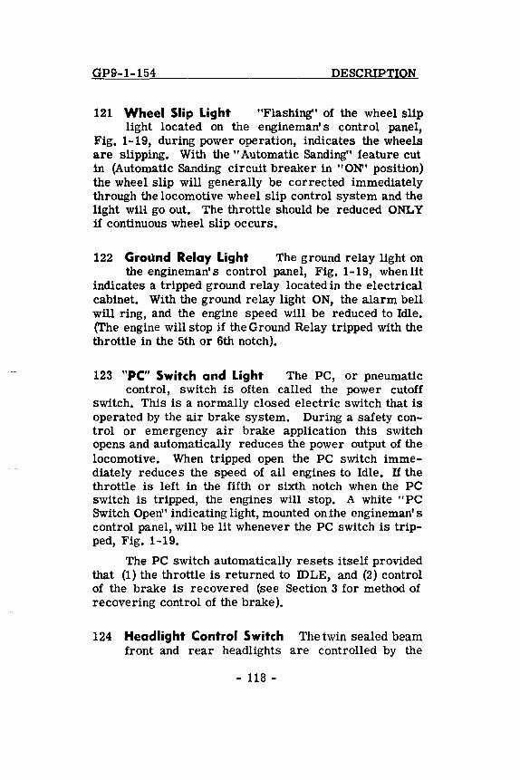
front and rear headlight circuit breakers on the engineman's control panel, Fig. 1-19. A dimming switch, Fig. 1-20, is mounted on one side of the controller.
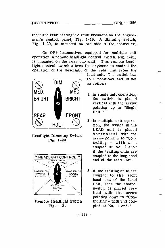
On GP9 locomotives equipped for multiple unit operation, a remote headlight control switch, Fig. 1-21, is mounted on the rear cab wall. This remote headlight control switch allows the engineer to control the operation of the headlight of the rear unit from the
~ DIM ~ MED. MED. BRIGHT BRIGHT
REAR FRONT
~ HOLT. ~ Headlight Dimming Switch
Fig. 1-20
FROM ANOTHER UNITCQUPLED AT EITHER END
CONTROL 0
WIT" UNIT GOUPlEDAT NO I END
Remote Headlight Switch Fig. 1-21
lead unit. The switch has four positions and is set as follows:
1. In single unit operation, the switch is placed vertical with the arrow pointing up to "Single Unit. "
2. In multiple unit operation, the switch in the LEAD unit is placed horizontal with the arrow pointing to "ContrOlling - wit hun it coupled at No. 2 end" if the trailing units are coupled to the long hood end of the lead unit.
3. If the trailing units are coupled to the short hood end of the Lead Unit, then the control switch is placed vertical with the arrow pointing down to "Controlling - with unit coupled at No. 1 end."
- 119 -
GP9-1-156 DESCRIPTION
4. In the last unit of the locomotive conSist, thE' headlight control switch is placed horizontal with arrow pointing to "ControUed" position.
NOTE: When more than two units are coupled together, the headlight control switch in aU-units, coupled between the lead unit and last unit of the consist, MUST be placed vertical with the arrow pointing up to "Single unit or intermediate units."
125 Air Brake Gauges These are standard gauges mounted on the engine man' s control panel. Each
gauge is clearly labeled as to its function.
ELECTRICAL CONTROL CABINET
The electrical control cabinet contains the various contactors, relays and other equipment necessary for the electrical and electro-pneumatic control of the unit. It forms the rear wall of the cab and is accessible from both the cab and engine room sides.
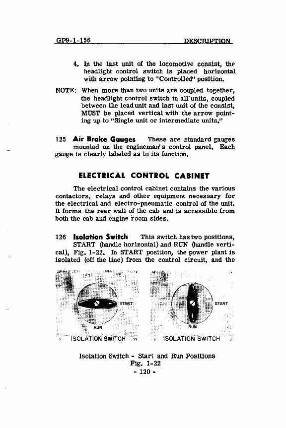
126 Isolation Switch This switch has two positions, START (handle horizontal) and RUN (handle verti
cal), Fig. 1-22. In START position, the power plant is isolated (off the line) from the control circuit, and the
START START
ISOLAr:ioN SWITCH ISOLAr:IOi,r"SWITCH
Isolation SWitch - start and Run Positions Fig. 1-22 - 120-
DESCRIPTION GP9-1-1256
engine speed is reduced to idle. The engine will remain at idle speed and will not respond to throttle control. The power contactors in the electrical control cabinet will not operate when control levers are normal. The "Alternator Failure" light and alarm bell is inoperative.
Engine START and STOP buttons are effective only with the isolation switch in the START position.
The isolation switch must be in the RUN position for the unit to develop power. The isolation switch should be moved only with the engine at idle speed or stopped. Use the manual lays haft lever to bring the engine to idle or stop when the locomotive is under power or in dynamic braking. If the isolation switch is in the START position,. do not place it in RUN while operating in dynamiC braking.
127 Engine Start and Stop Buttons The engine start and stop buttons located on the rear cab
wall, are operative only with the isolation switch in the START position. When starting the Diesel engine, press START button in firmly, and hold until engine starts (not more than fifteen seconds). To normally stop engine, press STOP button in firmly and hold in until engine stops.
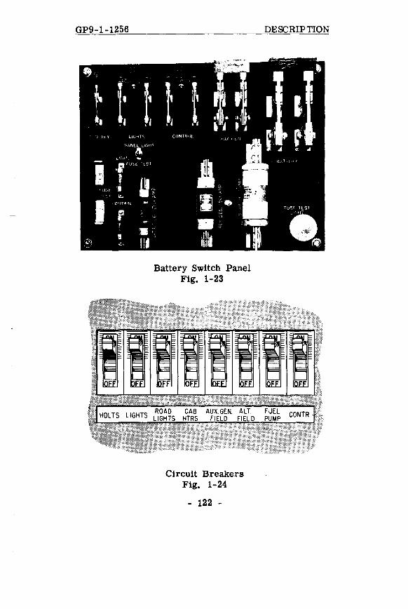
128 Fuses-Knife Switches and Circuit Breakers Located on the cab side of the electrical control
cabinet, are the following fuses, knife Switches, Fig. 1-23 and circuit breakers, Fig. 1-24.
1. Ground Relay Knife Switch 2. Main "Lights" Switch 3. Main "Control" Switch 4. Auxiliary Generator Switch 5. Main Battery Switch 6. 30 Amp. Control and Light Fuses 7. 80 Amp. Battery Field Fuse 8. 150 or 250 Amp. Auxiliary Generator Fuse 9. 400 Amp. Starting Fuse
10. Circuit Breakers - Rear Cab Wall
- 121 -
GP9-1-1256
Battery Switch Panel Fig. 1-23
Circuit Breakers Fig. 1-24
- 122 -
DESCRIPTION
DESCRIPTION GP9-1-156
For proper locomotive operation, all fuses must be good and securely in place, all knife switches should be closed and the above circuit breakers should be in the ON position in all units of the locomotive consist.
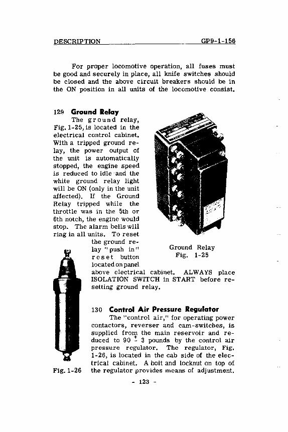
12~ Ground Relay The ground relay,
Fig. 1-25, is located in the electrical control cabinet. With a tripped ground relay, the power output of the unit is automatically stopped, the engine speed is reduced to idle· and the white ground relay light will be ON (only in the unit affected). If the Ground Relay tripped while the throttle was in the 5th or 6th notch, the engine would stop. The alarm bells will ring in all units. To reset
the ground relay "push in" res e t button located on panel
Ground Relay Fig. 1-25
above electrical cabinet. ALWAYS place ISOLATION SWITCH in START before re-setting ground relay.
130 Control Air Pressure Regulator The" control air," for operating power
contactors, reverser and cam-switches, is supplied from the main reservoir and reduced to 90 -: 3 pounds by the control air pressure regulator. The regulator, Fig. 1-26, is located in the cab side of the electrical cabinet. A bolt and locknut on top of
Fig. 1-26 the regulator provides means of adjustment.
- 123 -
GP9-1-1256 DESCRIPTION
A control air pressure gauge, with a name-plate "ELECTRIC AIR PRESSURE," is mounted On the rear wall of the cab. For proper locomotive operation this
't-gauge should read 90 - 3 pounds.
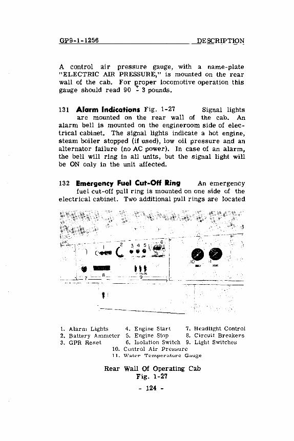
131 Alarm Indications Fig. 1-27 Signal lights are mounted on the rear wall of the cab. An
alarm bell is mounted on the engineroom side of electrical cabinet. The signal lights indicate a hot engine, steam boiler stopped (if used), low oil pressure and an alternator failure (no AC power). In case of an alarm, the bell will ring in all units, but the signal light will be ON only in the unit affected.
132 Emergency Fuel Cut-Off Ring An emergency fuel cut-off pull ring is mounted on one side of the
electrical cabinet. Two additional pull rings are located
I
l~ ..i~ 7 __ .~--
fl
2
(..,
." 9~_"" ___ J
1. Alarm Lights 4. Engine Start 7. Headlight Control 2. Battery Ammeter 5. Engine Stop 8. Circuit Breakers 3. GPR Reset 6. Isolation Switch 9. Light Switches
10. Control Air Pressure 1 L Water Terrtperarure Gauge
Rear Wall Of Operating Cab Fig. 1-2.7
- 124 -
DESCRIPTION GP9-1-156
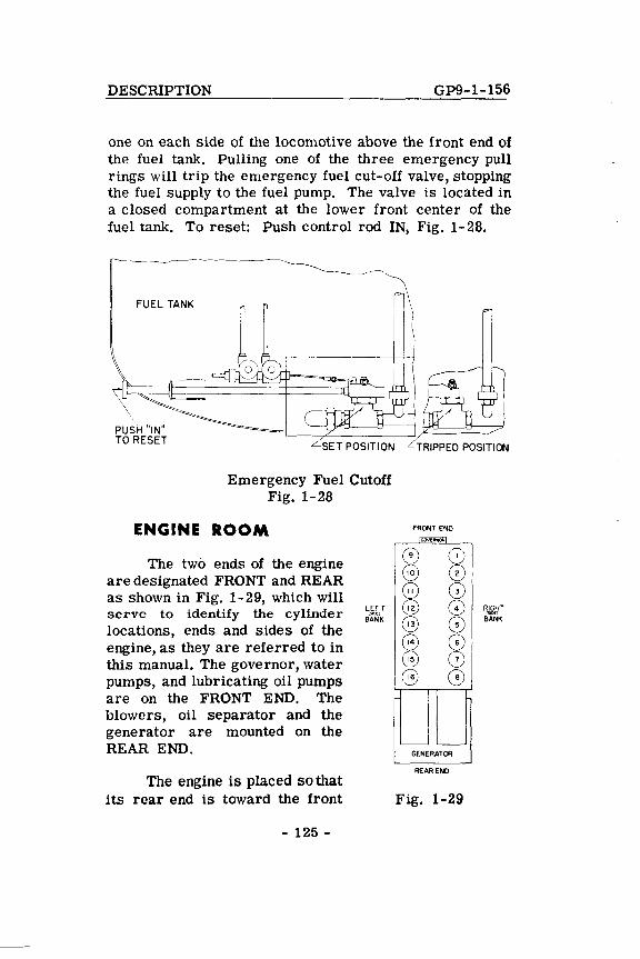
one on each side of the locomotive above the front end of the fuel tank. Pulling one of the three emergency pull rings will trip the emergency fuel cut-off valve, stopping the fuel supply to the fuel pump. The valve is located in a closed compartment at the lower front center of the fuel tank. To reset: Push control rod IN, Fig. 1-28.
FUEL TANK
PUSH "IN" TO RESET
r
Emergency Fuel Cutoff Fig. 1-28
ENGINE ROOM
The two ends of the engine are designated FRONT and REAR as shown in Fig. 1-29, which will serve to identify the cylinder locations, ends and sides of the engine, as they are referred to in this manual. The governor, water pumps, and lubricating oil pumps are on the FRONT END. The blowers, oil separator and the generator are mounted on the REAR END.
The engine is placed so that its rear end is toward the front
- 125 -
FRONT END
~
0 (0 @ 0 G G) @ 0 @ 0
~ CD 15 0
@ G
'--- '---GENERATOR
REAR END
Fig. 1-29
GP9-1-154 DESCRIPTION
end of the unit when the unit is operating in its normally forward direction.
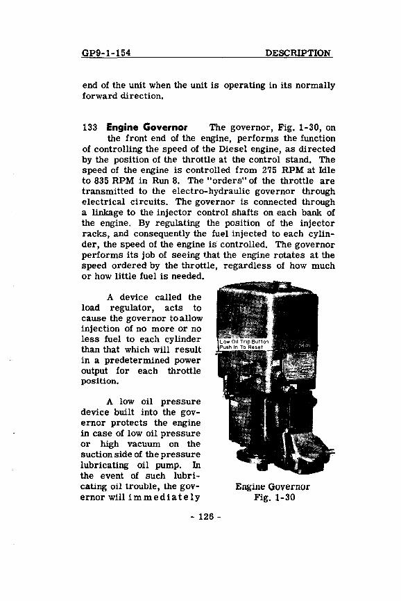
133 Engine Governor The governor, Fig. 1-30, on the front end of the engine, performs the function
of controlling the speed of the Diesel engine, as directed by the position of the throttle at the control stand. The speed of the engine is controlled from 275 RPM at Idle to 835 RPM in Run 8. The "orders" of the throttle are transmitted to the electro-hydraulic governor through electrical circuits. The governor is connected through a linkage to the injector control shafts on each bank of the engine. By regulating the position of the injector racks, and consequently the fuel injected to each cylinder, the speed of the engine is controlled. The governor performs its job of seeing t.hat the engine rotates at the speed ordered by the throttle, regardless of how much or how little fuel is needed.
A device called the load regulator, acts to cause the governor to allow injection of no more or no less fuel to each cylinder than that which will result in a predetermined power output for each throttle position.
A low oil pressure device built into the governor protects the engine in case of low oil pressure or high vaCUum on the suction side of the pressure lubricating oil pump. In the event of such lubricating oil trouble, the governor will immediately
- 126 -
Engine Governor Fig. 1-30
DESCRIPTION GP9-1-154
stop the engine and light the yellow low oil alarm signal in the unit affected. The alarm bell will ring in all units. When the engine stops, the "Blue" Alternator Failure Light will also be ON in the unit affected.
When the governor low oil pressure device stops the engine, a push button protrudes from the front of the governor housing and exposes a red band around the shaft of button. This push button must be pressed IN and the Isolation Switch moved to START position to turn off alarm bell. The low oil button will not trip if the engine is stopped by any means other than oil trouble.
If an engine is stopped by the governor low oil device, the push button must be reset before the engine can again be started. When the engine is started and run at idling speed, the governor will again stop the engine after approximately forty seconds, if the condition remains which caused the original shutdown. The engine should not be repeatedly started if the governor persists in shutting the engine down. If an attempt is made to run the engine above idling speed during the delay period, the governor will immediately stop the engine if the oil pressure and suction are not normal.
Load Regulator Fig. 1-31
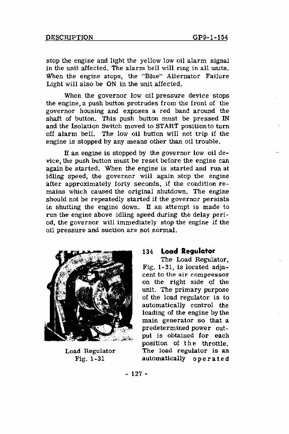
134 Load Regulator The Load Regulator,
Fig. 1-31, is located adjacent to the air compressor on the right side of the unit. The primary purpose of the load regulator is to automatically control the loading of the engine by the main generator so that a predetermined power output is obtained for each posi tion of the throttle. The load regulator is an automatically 0 per ate d
- 127 -
GP9-1-156
To Set
Engine Overspeed Trip Fig. 1-32
DESCRIPTION
rheostat connected in series with the main generator ba tte ry field. (The main generator bat t e r y field is a low voltage externally excited·field.)
The Load Regulator is in minimum field when the brush arm, as viewed through the window, is in the four 0' clock pOSition. Maximum field is obtained with the brush arm in the eight 0' clock position.
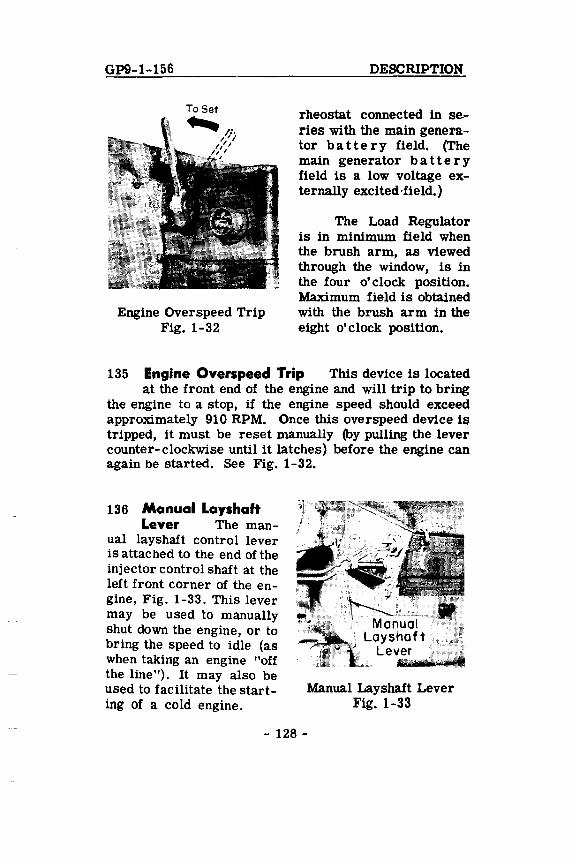
135 Engine Overspeed Trip This device is located at the front end of the engine and will trip to bring
the engine to a stop, if the engine speed should exceed apprOximately 910 RPM. Once this overspeed device is tripped, it must be reset manually (by pulling the lever counter-clockwise until it latches) before the engine can again be started. See Fig. 1-32.
136 Manual Layshaft Lever The man-
ual layshaft control lever is attached to the end of the injector control shaft at the left front corner of the engine, Fig. 1-33. This lever may be used to manually shut down the engine, or to bring the speed to idle (as when taking an engine "off the line "). It may also be used to facilitate the starting of a cold engine.
Manual Layshaft Lever Fig. 1-33
- 128 -
DESCRIPTION GP9.,.1-154
MISCELLANEOUS EQUIPMENT
137 Speed Recorder The speed recorder, located in front of the control stand, is a hydraulically
operated speed indicator with a speed recording tape and an odometer. It is driven from the number 2 axle of the unit, through a flexible cable.
Hand Brake Fig. 1-34
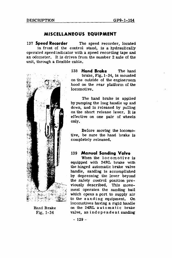
138 Hand Brake The hand brake, Fig. 1-34, is mounted
on the outside of the engineroom hood on the rear platform of the locomotive.
The hand brake is applied by pumping the long handle up and down, and is released by pulling on the short release lever. It is effective on one pair of wheels only.
Before moving the locomotive, be sure the hand brake is completely released.
139 Manual Sanding Valve When the I 0 com 0 ti ve is
equipped with 24RL brake with the hinged automatic brake valve handle, sanding is accomplished by depressing the lever beyond the safety control position previously described. This movement operates the sanding bail which opens a port to supply air to the sanding equipment. On locomotives having a rigid handle on the 24RL automatic brake valve, an independent sanding
- 129 -
GP9-1-154 DESCRIPTION
valve is installed. This valve is operated by mOving the lever forward or backward until it latches. Locomotives equipped with 6BL brake equipment have a sanding valve mounted on the brake valve assembly. The sanding operating valve has three positions: Forward, OFF and Reverse, which allows application of sand for movement in either direction.
140 Classification Lights Four permanently fixed clear bull's-eye lenses are prOvided, two on the
front of the short locomotive hood and two on the rear of the locomotive. Inside the hood and behind each bull'seye, a small compartment contains the classification light bulb and colored lenses. Red and green lenses are provided in each compartment which can be moved into a position between the bulb and the bull's-eye. To accomplish thiS, a locking pin is removed, the desired lens swung into place and the locking pin replaced. The colored lenses are accessible from the inside of the hood through hinged doors in the compartments. When both red and green lenses are out of position the permanent bull's-eye lens will show a white light, thus making three colors available.
141 Horn Valves The horns are operated by air valves which are controlled by pull-cords, above
the control stand. The horn shut-off valve is located behind the engine man' s control panel adjacent to the short hood end compartment door.
142 Bell Ringer The locomotive Signal bell is nor-mally located behind the pilot on the right front end
of the locomotive. It is operated by an air valve located at the engine man' s station.
143 Windshield Wipers The windshield wipers, four in number, are controlled by valves over the
cab windows, two on each side of the cab. The wipers
- 130 -
DESCRIPTION GP9-1-1256
operate independently of each other. They should not be run on a dry window as dirt on the glass or blade will scratch the glass.
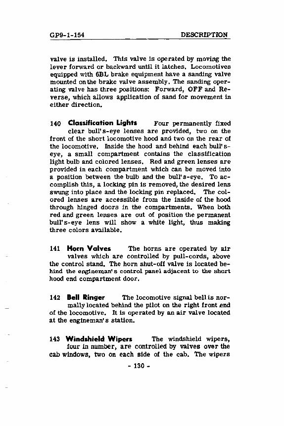
144 Cab Heaters and Defrosters The cab heaters cQmplete with defroster and fresh air ventilator,
are installed under each of the two fixed windows in the cab, Fig. 1-35. Fresh air is taken in through a louver in the cab wall under the fixed window and is controlled by a fresh air damper within the heater. An external knob, indicated by a descriptive nameplate, controls the fresh air damper position. Turn this knob clockwise to admit fresh air.
Controlled by a rheostat type switch, a 1/6th HP variable speed fan motor draws in fresh air or recir
Cab Heater, Defroster And Fresh Air Ventilator
Fig. 1-35
culates cab air. The fan forces air through a hot water radiator and exhausts the heated air out onto the cab floor. An outlet damper controls the amount of air leaving the heater at the floor level. Varying the setting of this outlet damper will also vary the amount of air being directed to the defroster outlet.
The defroster is a simple non-adjustable baffle and duct arrangement and the VOlume, temperature, and velocity of the discharged air is dependent upon the setting of the fresh air dam per, the outlet damper, and the speed of the motor.
- 131 -
GP9-1-156 DESCRIPTION
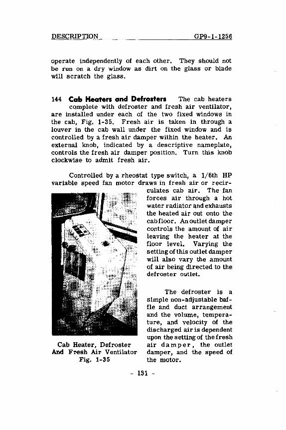
145 Trucks Two four-wheel flexible trucks are provided on each GP9 unit. The axles are all
equipped with Hyatt roller bearing journal boxes. A stench bomb on each journal box will release a pungent odor if the temperature inside the journal box exceeds 2200 F., Fig. 1-36.
Hyatt Journal Box Fig. 1-36
- 132 -
GP9-2-154 OPERATION
SECTION 2.
OPERATION
The successful and dependable operation of the locomotive is dependent upon the quality of inspection and repair at regular maintenance periods, as well as the proficiency of the operating crews. As a supplement to the regular terminal maintenance, a ''pre-service check" should be made by the engine crew upon boarding the locomotive.
BASIC INFORMATION
200 When Boarding the Locomotive
A. Ground Inspection - Locomotive Exterior and Running Gear.
Check For:
1. Fuel oil, lube oil, water or air leaking from the locomotive.
2. Loose or dragging parts.
3. Proper pOSitioning of angle cocks and shut off valves.
4. Observe brake cylinder piston travel, if air brakes are set.
5. Condition of brake shoes.
6. Drain condensate from 12 main reservoir.
7. Adequate fuel supply showing in fuel tank full length sight glass.
B. Proper connection of air hoses and jumper cable (if used in multiple unit operation).
- 200-
OPERATION GP9-2-156
B. Engineroom Inspection - Long Hood End
(H Diesel engine is stopped see Arts. 201 and 202 for starting instructions).
With Diesel engine running, check:
1. Lubricating oil supply. a. Diesel engine oil pan dipstick b. Governor sight glass c. Air compressor sight glass
2. Diesel engine lube oil pressure gauge.
3. Fuel flow in fuel return sight glass.
4. Check for oil, water and fuel leaks.
5. Engine COOling water level in supply tank.
6. Drain condensate from #1 main reservoir sump tank.
7. Close air box drain valves.
C. Operating Cab Inspection
Check:
1. "Control and Fuel Pump" and "Engine Run" circuit breakers must be in "ON" position.
2. Place throttle lever in Idle, the reverse lever in neutral and selector lever in No. 1 position.
3. Check position of the automatic and independent brake valves. Apply locomotive brakes.
4. Brake pipe cutout cock should be "cut in."
5. Rotair valve (locomotive equipped with 24RL brake) should be" in "Passenger" or "Freight" position depending upon the service required.
6. If engine is stopped, place isolation switch in START. See Arts. 201 and 202 for engine
- 201 -
GP9-2-154 OPERATION
starting instructions. If engine is running, place isolation switch in RUN.
7. Place "Headlight Control" switch in "Single Unit" position or proper "Controlling" position if operating in Multiple Unit.
8. Place unit selector switch in proper position if equipped with dynamic braking.
9. In the electrical cabinet, all fuses must be securely in place, all knife switches closed and circuit breakers should be in the It ON" position.
10. Check steam generator water supply at remote water level gauge.
11. If engine is running, check battery ammeter.
D. Trailing Cab Inspection (Multiple Unit Operation)
Check:
1. All circuit breakers at engineman IS control station should be in OFF position.
2. Throttle lever should be in Idle, selector lever in OFF pOSition, and reverse lever removed from the control stand.
3. Independent brake valve should be in Release position.
4. Automatic brake valve should be in Running position (locomotive equipped with 24RL brake) or in "LAP" position (locomotive equipped with 6BL brake).
5. Rotair valve (locomotive equipped with 24RL brake) should be in the proper LAP position.
6. Brake pipe cutout cock should be in "Trailing" (6BL) or 'OUT" (24RL) position.
7. If engine is stopped, place isolation switch in Start. See Arts. 201 and 202 for engine starting
- 202 -
OPERATION GP9-2-156
instructions. If engine is running, place isolation switch in RUN.
8. Place "Headlight Control" switch in "Controlled" position if unit is last in consist. Place "Headlight Control" switch in"Single or Intermediate" position if unit is between the lead and last unit of the consist.
9. In the electrical cabinet: See that all fuses are in place, all knife switches closed and the circuit breakers are in the ON position.
10. If engine is running, check battery ammeter.
11. Check steam generator water supply at remote water level gauge.
201 Precautions Before Starting Engine
The following items should be performed when an engine is to be started after a layover.
1. With locomotive stopped, place the independent brake valve in FULL application position.
2. Check pOSition of all valves: Drains in cooling system, lube oil system and air reservoirs.
3. Check engine cooling water level.
4. Check lube oil supply. a. In Diesel engine oil pan. b. In engine governor c. In air compressor.
5. Place the isolation switch in START position.
6. In the electrical cabinet: All fuses must be in place, all knife switches closed and the circuit breakers should be in the ON position.
7. Reverse lever must be in Neutral.
- 203 -
GP9-2-156 OPERATION
8. At the engineman's control station, place the "Control ~nd Fuel Pump" and "Engine Run" circuit breakers in the "ON" position.
NOTE: When operating the GP9 as a lead unit in multiple with older type units not equipped with an "Engine Run" circuit breaker, the "Engine Run" circuit breaker on the lead GP9 must be "ON" to start and keep the fuel pumps of the trailing older type units running.
9. Check the PCS light - it should be OFF.
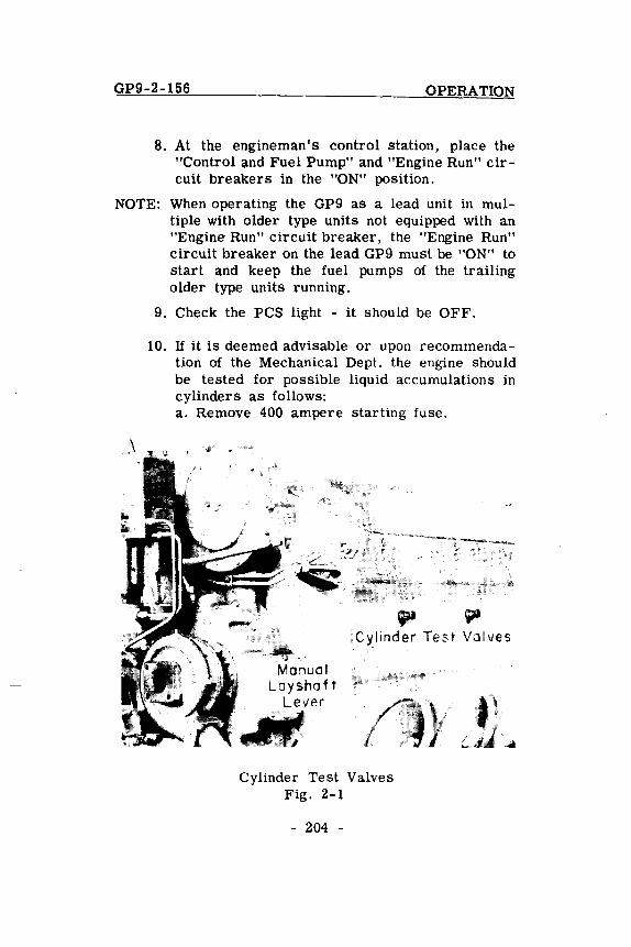
10. If it is deemed advisable or upon recommendation of the Mechanical Dept. the engine should be tested for possible liquid accumulations in cylinders as follows: a. Remove 400 ampere starting fuse.
ill ~ Cylinder Test Valves
Manual Layshaf t
Lever IIIitiIiI
f//IIf7J
Cylinder Test Valves Fig. 2-1
- 204 -
}

OPERATION GP9-2-156
b. Open all engine cylinder test valves (3 full turns) Fig. 2-1.
c. Rotate engine at least one complete revolution using engine turning jack. Observe test valve, for liquid discharge.
d. If liquid is discharged from any test valve, engine should not be started until cause of accumulation has been determined and either corrective steps taken or authority to proceed given.
e. Close cylinder test valves. f. Replace 400 ampere starting fuse.
202 To Start Engine After completing the items mentioned in Art. 201, the engine is started by
performing the following steps:
1. Check for fuel flow through "return fuel sight glass" on fuel filter mounted on front of engine, Fig. 2-2.
2. Check position of overspeed trip,
3. Check position of governor low oil trip button.
Overspeed Trip To Set ~~,.... ,~~ -----..' .....
Overspeed Trip And Fuel Flow Check Fig. 2-2
- 205 -
GP9-2-156 OPERATION
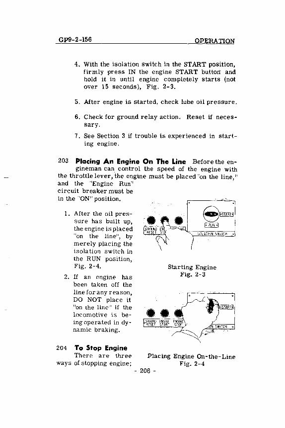
4. With the isolation switch in the START position, firmly press IN the engine START buttorr and hold it in until engine completely starts (not over 15 seconds), Fig. 2-3.
5. After engine is started, check lube oil pressure.
6. Check for ground relay action. Reset if necessary.
7. See Section 3 if trouble is experienced in starting engine.
203 Placing An Engine On The Line Before the en-gineman can control the speed of the engine with
the throttle lever, ·the engine must be placed "on the line," and the "Engine Run" circuit breaker must be in the "ON" position.
1. After the oil pressure has built up, the engine is placed "on the line", by merely placing the isolation switch in the RUN position, Fig. 2-4.
2. If an engine has been taken off the line for any reason, DO NOT place it "on the line" if the locomotive is being operated in dynamic braking.
204 To Stop Engine There are three
ways of stopping engine;
ISOL~TION SWITCH
Starting Engine Fig. 2-3
Placing Engine On-the-Line Fig. 2-4
- 206 -
OPERATION GP9-2-1256
these can be designated as (1) normal (2) under power and (3) emergency.
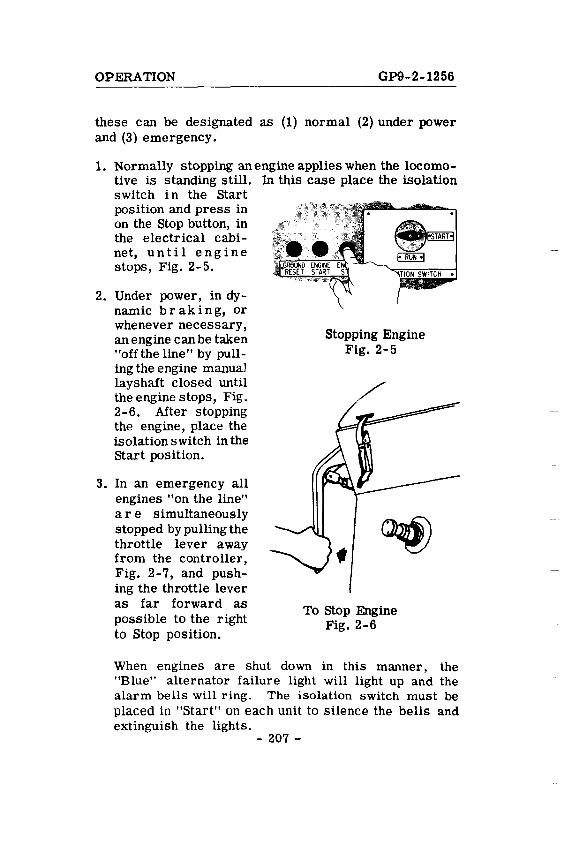
1. Normally stopping an engine applies when the locomotive is standing still. In this case place the isolation switch in the Start position and press in on the stop button, in the electrical cabinet, until engine stops, Fig. 2-5.
2. Under power, in dynamic braking, or whenever necessary, an engine can be taken "offthe line" by pulling the engine manuaJ lays haft closed until the engine stops, Fig. 2-6. After stopping the engine, place the isolation switch in the Start position.
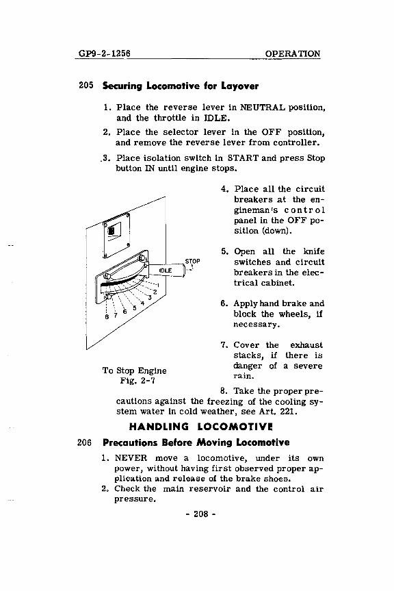
3. In an emergency all engines "on the line" are simultaneously stopped by pulling the throttle lever away from the controller, Fig. 2-7, and pushing the throttle lever as far forward as possible to the right to Stop position.
nON SWITCH.
Stopping Engine Fig. 2-5
To Stop Engine Fig. 2-6
When engines are shut down in this manner, the "Blue" alternator failure light will light up and the alarm bells will ring. The isolation switch must be placed in "Start" on each unit to silence the bells and extinguish the lights.
- 207 -
GP9-2-1256 OPERATION
205 Securing Locomotive for Layover
1. Place the reverse lever in NEUTRAL position, and the throttle in IDLE.
2. Place the selector lever in the OFF position, and remove the reverse lever from controller .
. 3. Place isolation switch in START and press Stop button IN until engine stops.
To Stop Engine Fig. 2-7
4. Place all the circuit breakers at the engineman's con tr 0 I panel in the OFF position (down).
5. Open all the knife switches and circuit breakers in the electrical cabinet.
6. Apply hand brake and block the wheels, if necessary.
7. Cover the exhaust stacks, if there is danger of a severe rain.
8. Take the proper precautions against the freezing of the cooling system water in cold weather, see Art. 221.
HANDLING LOCOMOTIVE
206 Precautions Before Moving Locomotive
1. NEVER move a locomotive, under its own power, without having first observed proper application and release of the brake shoes.
2. Check the main reservoir and the control air pressure.
- 208 -
OPERATION GP9-2-156
3. Release hand brakes and remove any blocking of the wheels.
4. See that ground relays are set and isolation switches in "Run" position.
207 Handling Light Locomotive With the engines placed "on the line" and cab preparations completed
the locomotive is handled as follows:
1. Move "Generator Field" circuit breaker to ON.
2. Insert and move the reverse lever to the desired position. (This lever is to be moved ONLY when the locomotive is standing still.)
3. Place the selector lever in the No. 1 position.
4. Depress safety control foot pedal (if used).
5. Release the air brakes.
6. When running light, open the throttle a notch at a time. When kicking cars etc., the throttle may be advanced as far and as rapidly as needed.
208 Coupling To Train and Pumping Up Air After coupling to a train, stretch coupling to make sure
it is properly made. If main reservoir pressure falls below feed valve setting when brakes are cut in, proceed as follows:
1. Place "Generator Field" circuit breaker in "OFF" position.
2. Place reverse lever in Neutral.
3. Open throttle to 4th, 5th or 6th notch as needed.
209 Starting a Train Starting a train depends not only on the kind of locomotive being used, but also
on the type, length, weight, grade, weather conditions
- 209 -
GP9-2-1256 OPERATION
and the amount of slack in the train. Because of the locomotive's very HIGH STARTING TRACTIVE EFFORT it is important that the air brakes be CO:MPLETELY released before attempting to start the train. Actual tests have shown that a 100 car train, having the average uniformly distributed leakage, may require 9 minutes to completely release the brakes. It requires approximately 30 minutes (with 130 pound main reservoir' pressure) to completely charge a depleted air system on a similar 100 car train.
The load indicating meter, Fig. 2-8, can be used as a PULL METER to judge the tractive effort of the locomotive. Merely looking at the ground and listening to the engine exhaust may give a false indication of the locomotive's draw bar pull.
The GP9 locomotive is designed to have about the same rapid yet smooth power build-up characteristics of previous Model GP7 and other EMD locomotives having governors set for a modified maximum field start.
As the throttle is open to the first notch, a definite power build up will be noted. Any further advancement
Load Indicating Meter Fig. 2-8
- 210 -
OPERATION GP9-2-156
of the throttle is accompanied by an almost immediate additional increase in power. This may be seen by observing the speed with which the load indicating meter responds to throttle advance.
With a power control of this type the rate and extent of power build-up is left largely to the desire of the engineman yet is still controlled by the load regulator and engine governor.
When ready to start, the following general procedure is recommended:
1. Place the selector lever in the No. 1 position and move the reverse lever to the desired direction.
2. Place foot on the safety control foot pedal (DEADMAN) and release the brakes.
3. Open the throttle one notch every 1 to' 2 seconds as follows: a. To Run 1 - note the load meter pOinter start
moving to the right. b. To Run 2 - note engine speed increase. At
an easy starting place, the locomotive may start the train in Run 1 or 2.
c. To Run 3 or higher (experience and the demands of the schedule will determine this) until the locomotive moves.
4. Reduce throttle one or more notches if acceleration is too rapid.
5. After the train is stretched, advance throttle as desired.
NOTE: If the wheel slip indicator flashes continuously, reduce the throttle one notch. Apply sand as needed to prevent further slipping and reopen the throttle when rail conditions improve. See Art. 210 - Automatic Sanding In Pow{!r.
- 211 -
GP9-2-154 OPERATION
Although it will generally be unnecessary to take slack in starting, there will be cases where it is wise to do so, after making sure that all brakes are released. The throttle should be opened one notch at a time, in starting the train. A TONNAGE TRAIN SHOULD BE STARTED IN AS LOW A THROTTLE POSITION AS POSSIBLE, BEARING IN MIND THAT THE SPEED OF THE LOCOMOTIVE MUST BE KEPT AT A MINIMUM UNTIL THE TRAIN HAS BEEN STRETCHED. Sometimes it is advisable to reduce the throttle a notch or two the moment the locomotive begins to move, in order to prevent stretching the slack too quickly. The engineman must be the judge of the acceleration and the conditions under which the train is being started.
When the locomotive has moved far enough to completely stretch the train, the throttle may be advanced as quickly as desired, but should not be advanced so quickly that slipping results. Smooth acceleration is obtained by opening the throttle one notch each time the pointer of the load meter begins moving to the left.
210 Automatic Sanding in Power GP9 locomotives are equipped with automatic sanding in power to
assist in controlling wheel Slip. When operating in transition one (1) (as in starting a train) sanding automatically takes place while slip is in its "creepll or initial stage. In this manner a wheel slip is ''anticipated'' and prevented before any appreciable loss of tractive effort occurs.
In transition 2, 3, and 4 (and on some occasions in transition 1) automatic sanding, caused by wheel slip, is accompanied by a reduction in main generator output.
Duration of sanding, after the wheel slip or creep has stopped, is controlled by the setting of a time delay sanding (TDS) relay. An off-on circuit breaker switch on the engineman IS control panel cuts in or out this sanding-in-power feature.
- 212 -
OPERATION GP9-2-1256
With the automatic sanding feature "cut-in" (AutoSanding circuit breaker in ON position) throttle reduction to avoid repeated wheel slip will rarely be necessary. Also, manual operation of the sanders by the engineman at points on the road where slippage is likely to occur can be eliminated.
211 Acceleration of a Train After the throttle is in the 8th notch and the train begins to accelerate,
the indicating meter pointer will move slowly to the left. Forward and backward transition will automatically take place without any attention on the part of the engine man, other than necessary throttle reductions to keep under any speed restriction.
212 Slowing Down Because of a Grade As the train slows down on a grade the pOinter on the indi
cating meter will move slowly toward the right. Backward transition will take place automatically.
213 Locomotive Operation At Very Slow Speeds The operation of a GP9 locomotive, regardless of
gear ratio, is not governed by any specific short time ratings.
In most cases, the locomotive may be operated up to the limit of the adheSion attainable.
GP9 locomotives pulling tonnage trains at very slow speeds should be operated with the throttle in Run 8 position. In the event of a wheel slip indication (wheel slip light flashes on), the locomotive wheel slip control system will automatically apply sand to the rails (AutoSanding circuit breaker in ON position) and reduce power to a point where slipping stops. If continuous wheel Slipping on sand occurs, due to unusual rail operating
- 213 -

GP9-2-1256 OPERATION
conditions, the throttle can be reduced for short periods. Under thest: circumstances, the Gpg locomotive can operate at reduced throttle, provided it is not necessary to reduce below the 5th throttle notch to correct for a continuous wheel slip. If slipping persists, tonnage should be reduced.
If there are any questions about an unusual operation of the locomotive, such as a passenger locomotive operating in freight service, Electro-Motive will, upon request, analyze the actual operation and make specific recommendations.
BRAKING
214 Air Braking With Power The method of hand-ling the air brake equipment is left to the discre
tion of the individual railroad. However, when braking with power it must be remembered that for any given throttle position the draw bar pull rapidly increases as the train speed decreases. This pull might become great enough to part the train unless the throttle is reduced as the train speed drops. Since the pull of the locomotive is indicated by the amperage on the load meter, the engine man can maintain a constant pull on the train during a slow down, by keeping a steady amperage on the load meter. This is accomplished by reducing the throttle a notch whenever the amperage starts to increase. It is recommended that the independent brakes be kept fully released during power braking. The throttle MUST be in Idle before the locomotive comes to a stop.
MISCELLANEOUS OPERATING
INSTRUCTIONS
215 Multiple Unit Operation In operating GP9 units in multiple with each other or with GP7 units, the
operating controls of the locomotive are set up as outlined in Art. 217. When set up for multiple unit operation, the following operating precautions should be observed.
- 214 -
OPERATION GP9-2-1256
If the Wlits of the consist are of different gear ratios, the locomotive should not be operated at speeds in excess of that recommended for the Wlit having the lowest maximum permissible speed.
If some of the Wlits in the consist have an overload short time rating, the locomotive operation should be governed by the overload short time rating of the Wlit having the highest minimum speed.
216 Uncoupling and Coupling Units in Locomotive
1. To uncouple Wlits: a. Apply brakes and close angle cocks on both
WlitS on all air hoses. b. Take down all power plant jumper cables. c. Remove platform safety chains between
Wlits. d. Break hoses and separate WlitS by Wlcoupling.
2. In coupling WlitS: a. Couple and stretch Wlits to insure couplers
are locked. b. Connect hoses and jumpers, and be sure all
necessary angle cocks are opened. c. Attach platform safety chain between Wlits. d. In any non-operating cab, cut-out the brakes
and place all circuit breakers at the engineman's control panel in "OFF" position. Remove the reverse lever from the controller in all trailing Wlits.
217 Changing Operating Ends When the consist Of the locomotive includes two or more WlitS with
operating controls, the following procedure should be followed in changing from one operating end to the oppOSite end.
- 215 -
GP9-2-154 OPERATION
1. Locomotives equipped with 24RL brake. a. If the locomotive is equipped with electro
pneumatic brakes and the brake has been in use, change the brake selector on the automatic brake valve to '~UTO" and open electro-pneumatic brake switch.
b. REMOVE REVERSE LEVER. c. With safety control foot pedal depressed,.
make an automatic 20 pound brake pipe reduction.
d. Move the independent brake valve handle to release position; observe that the locomotive brakes are still applied.
e. Release safety control foot pedal. f. Close brake pipe cut-out cock (double head
ing cock). g. Move the rotair valve to the "Passenger Lap"
or "Freight Lap" position depending on the service required.
h. Move the automatic brake valve handle to the RUNNING position and remove the handle from the brake valve.
i. Remove the independent brake valve handle in the RELEASE position.
j. Place all circuit breakers at the engineman IS control panel in OFF position.
k. Place "Headlight Control" switch in "Controlled" position.
1. Proceed to cab at opposite end. Check the PC switch light. Move "Control and Fuel Pump" and "Engine Run" circuit breakers, on the engineman IS control panel, to ON position and any other circuit breakers that are necessary.
m. Insert reverse lever, automatic brake valve and independent brake valve handles.
n. Move the rotair valve to the "FRGT." or "PASS." position, depending upon the service required.
- 216 -
OPERATION GP9-2-156
o. Place the independent brake valve handle in the FULL APPLICA TION position.
p. Open brake pipe cut-out cock (double-heading cock), slowly, pausing from five to ten seconds in mid-position.
q. Place unit selector switch in proper position if locomotive is equipped with dynamic braking. See Article 230.
r. Place "Headlight Control" switch in proper "Controlling" position.
s. When ready to move locomotive, depress safety control foot pedal or automatic brake valve handle and move the independent brake valve handle to RELEASE position.
2. Locomotives equipped with 6BL brake. a. REMOVE REVERSE LEVER. b. Make a full service brake pipe reduction. c. Move double heading cock to 'Trailing" (4
o Iclock) position and release safety control foot pedal (if used).
d. Move the independent brake valve handle to RELEASE position.
e. Leave the automatic brake valve handle in the LAP position.
f. Place all circuit breakers at engineman IS control station in 'Off" position.
g. Place "Headlight Control" switch in "Controlled" position.
h. Proceed to cab at opposite end. Check ''PC'' switch light, Move "Control and Fuel Pump" and 'Engine Run" circuit breakers to ON position and any other circuit breakers that are necessary.
i. Insert reverse lever and brake valve handles. Place independent bra k e valve in FULL APPLICATION position.
j. Open double heading cock to "Lead" (6 o Iclock) position slowly.
k. Place automatic brake in RUNNING position.
- 217 -
GP9-2-154 OPERATION
1. Place unit selector switch in proper position if locomotive is equipped with dynamic braking.
m. Place ''Headlight Control" switch in proper "Controlling" position.
n. When ready to move locomotive, depress safety control foot pedal (if used), and move independent brake valve to RE LEASE position.
NOTE: When the 6BL brake is equipped with safety control foot pedal or automatic train control, the N-1-A brake application valve is used. The three-position brake valve cut-out cock (double heading cock) is mounted on this N-1-A brake application valve instead of on the automatic brake valve. This cut-out cock is accessible through a small trap door in the cab floor.
218 Handling Locomotive Dead-In-Train
1. Air brake equipment. a. Place the independent and automatic brake
valve handles in the Release and Running positions respectively.
b. Move the double heading cock to the "Cutout" (24RL) or 'Dead" (6BL) position.
c. Open the dead engine cut-out cock. d. If the locomotive is equipped with 24RL
brake, move the Rotair valve to the passenger (PASS) position.
The locomotive brake will now operate like that of a car in the train.
2. Electrical control equipment. a. Remove the reverse lever from the controller. b. Place the isolation switch in the Start pOSi
tion. If it il5 necel5l5a.~y to keep the engine
- 218 ~
OPERATION GP9-2-154
idling while hauling locomotive, the "Control and Fuel Pump" circuit breaker must be left ON.
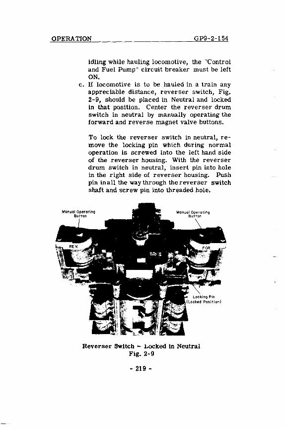
c. If locomotive is to be hauled in a train any appreciable distance, reverser switch, Fig. 2-9, should be placed in Neutral and locked in that position. Center the reverser drum switch in neutral by manually operating the forward and reverse magnet valve buttons.
To lock the reverser switch in neutral, remove the locking pin which during normal operation is screwed into the left hand side of the reverser housing. With the reverser drum switch in neutral, insert pin into hole in the right side of reverser housing. Push pin in all the way through the reverser switch shaft and screw pin into threaded hole.
Reverser Swltch - Locked in Neutral Fig. 2-9
- 219 -
GP9-2-1256 OPERATION
219 Doubleheading Prior to double heading be-hind another locomotive, make a full service brake
pipe reduction with the automatic brake valve and close the double heading cock. On locomotives equipped with 24RL brake, leave the Rotair valve in FRGT. or PASS. position depending upon the service required. Return the automatic brake valve handle to the running pOSition and place the independent brake valve in release position. The operation of the throttle is normal, but the brakes are controlled from the lead locomotive. The engineman on the second locomotive may make an emergency application of the brakes with automatic brake valve, and/or may release his locomotive brakes by depressing the independent brake valve handle, in the release position.
220 Operation In Helper Service BaSically, there is no difference in the instructions for operating
the GP9 locomotive as a helper or with a helper. In most cases the GP9 locomotive can be operated in either service up to the limit of the adhesion attainable. The throttle can be reduced to prevent excessive wheel slip, for short periods, but the locomotive should not be operated below the 5th throttle position.
If other Diesel locomotives having overload short time ratings are used with the GP9 locomotive in helper service, their operation will be governed by the permissible length of time the locomotives can operate at the short time ratings.
To obtain a maximum tonnage rating for any Single application, Electro-Motive will, upon request, analyze the actual operation and make specific tonnage rating recommendations.
ZZ1 freezlngWearher Precautions In freezing weather, precautions must be taken to see that
- 220 -
OPERATION GP9-2-154
water in the locomotive does not freeze when the engine is shut down for any reason. If trainline steam is not available, the entire system will have to be drained.
A. With steam from an external source supplied to the locomotive (engine and steam generator shut down) to prevent freezing, the following valves are to be opened:
1. Engine cooling system. a. Steam admission valve to engine cooling
water. b. IG" valve. c. Toilet water tank steam valve.
2. Steam generator. a. Heating coil valve. b. Water suction line valve. c. Water tank valve.
B. Infreezing weather if heating facilities are not available, all water must be drained from:
1. Engine cooling system. Also, remove pipe plug from bottom of right water pump housing.
2. Steam generator.
3. Steam generator water tank.
4. Toilet water tank.
5. Air system. a. Air compressor oil separator. b. Sump reservoir. c. Main reservoirs. d. Type H filter. e. Electrical control air regulator. f. Electrical contrQI air reservoir. g. Air compressor intercooler. h. Air strainers.
- 221 -
GP9-2-156 OPERATION
222 Operation Over Railroad Crossings When crossing railroad crossings, reduce throttle to the
5th notch before reaching crossing and leave reduced until all locomotive units are over crossing. This will reduce arcing from the brushes to the motor commutator.
223 Running Through Water Under ABSOLUTELY NO circumstances s h 0 u I d the locomotive pass
through water which is deep enough to touch the bottom of the traction motor frames. When passing through water, always go at a very slow speed (2 to 3 miles per hour). Water any deeper than three inches above the top of the rails is likely to cause damage to the traction motors.
224 ReseHing PC Switch After Safety Control Application
1. CLOSE THROTTLE TO IDLE.
2. Place automatic brake valve in LAP.
3. Place foot on safety control foot pedal (if used).
4. Wait until application pipe pressure is normal; Listen for exhaust or watch the "PC Switch Open" light. If the PC switch does not reset itself with the automatic brake valve in' LAP, move the brake valve to the RUNNING position. The PC switch is properly set when the light goes out.
225 Ground Relay Action When this protective device is tripped the engine will not speed up when
throttle is opened and no power will be developed; the alarm bell will ring and the ground relay light (White) on the engineman's control panel will be on. If the ground relay trips, while the throttle is in Run 5 or 6, the engine will stop. To reset: isolate engine, depress
- 222 -
OPERATION GP9-2-156
relay reset button and put engine "on the line." If relay continues to trip isolate unit.
226 Wheel Slip Indication The wheel slip light will flash on immediately when a pair of wheels has
slipped. The detection of wheel slip action automatically reduces the application of power to stop the slipping; the power will be reapplied after slipping has stopped.
It will generally be unnecessary to reduce the throttle because of momentary wheel slip action. Sand may be applied to prevent repeated wheel slipping which may occur under extremely poor rail conditions.
227 Indication of a Pair of Wheels Sliding If one pair of wheels should slide when starting a train,
the wheel slip light will flash on and off intermittently. As the train speed increases, the light will stay on more or less continuously and will not go out when the throttle is reduced. The light will go out when throttle is closed to idle.
If sliding is suspected, the engine crew should make an immediate investigation to determine the cause. The wheels may be sliding due to a locked brake, a broken gear tooth wedged between the pinion and ring gear, etc.
Repeated ground relay action, accompanied with unusual noises such as continuous thumping or squealing, may also be an indication of serious traction motor trouble that should be investigated at once.
IF AN ENGINE MUST BE ISOLA TED BECAUSE OF REPEATED WHEEL SLIP OR GROUND RELAY ACTION J DO NOT ALLOW THAT UNIT TO REMAIN IN THE LOCOMOTIVE CONSIST UNLESS IT IS CERTAIN THA T ALL OF ITS WHEELS ROTATE FREELY.
- 223 -
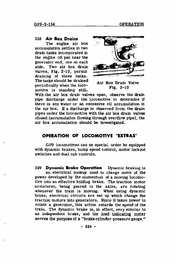
GP9-2-154
228 Air Box Drains The engine air box
accumulation settles in two drain tanks incorporated in the engine oil pan near the generator end, one on each side. Two air box drain valves, Fig. 2-10, permit draining of these tanks. The tanks should be drained periodically when the locomotive is standing still.
OPERATION
Air Box Drain Valve Fig. 2-10
With the air box drain valves open, observe the drain pipe discharge under the locomotive to determine if there is any water or an excessive oil accumulation in the air box. U a discharge is observed from the drain pipes under the locomotive with the air box drain valves closed (accumulation flowing through overflow pipe), the air box accumulation should be investigated.
OPERA TIOH OF LOCOMOTIVE "EXTRAS"
GP9 locomotives can on special order be equipped with dynamic brakes, hump speed control, motor lockout switches and dual cab controls.
229 Dynamic Brake Operation Dynamic braking is an electrical hookup used to change some of the
power developed by the momentum of a moving locomotive into an effective holding brake. The traction motor armatures, being geared to the axles, are rotating whenever' the train is moving. When using dynamic brake, electrical circuits are set up which change the traction motors into generators. Since it takes power to rotate a generator, this action retards the speed of the train. The dynamic brake is, in effect, very similar to an independent brake, and the load indicatlng meter serves the purpose of a "brake cylinder pressure gauge."
- 224 -
GP9-2-1256 OPERATION
In descending a grade, with throttle in Idle position, drawbar "push" of the trailing train tonnage moves the locomotive forward. If no resistance other than the locomotive and the wheel friction is exerted against this "push," the momentum of the train on the descending grade would soon reach a speed where the train brakes would have to be applied. In dynamic brake, a resistance to this drawbar push is set up which in effect "holds back" the speed of the train as would the application of the locomotive independent brake. The effect of the resistance is to slow down the traction motor armatures being driven by the "push" of the train.
The resistance set up in each traction motor is a magnetic field through which the traction motor armature must rotate. Increasing the strength of the magnetic field will effect a "slow down" of the traction motor armature, thus holding back the train. The magnetic field is produced by connecting the traction motor fields of each unit in series with the main generator, and passing a current through these fields. The strength of the magnetic field is varied by varying the main generator current to the traction motor fields in each unit.
The main generator battery field of each unit in the locomotive consist is connected in series to the low voltage supply of the lead unit. This is called the "field loop" circuit. Movement of the selector lever in the lead unit into the "B" braking position, sets up the controller for the throttle lever to control the position of the load regulator which in turn regulates the main generator battery field current for dynamic braking. The throttle moves a 499 ohm rheostat which acts through a micropositioner relay (LRP) , Fig. 2-11, to pOSition the load regulator. ~oving the throttle lever toward the 8th notch and away from idle increases the effectiveness of the "holding brake." Thus, in effect, the strength of the traction motor field in which the traction motor armature must rotate is controlled by the throttle lever.
- 225 -
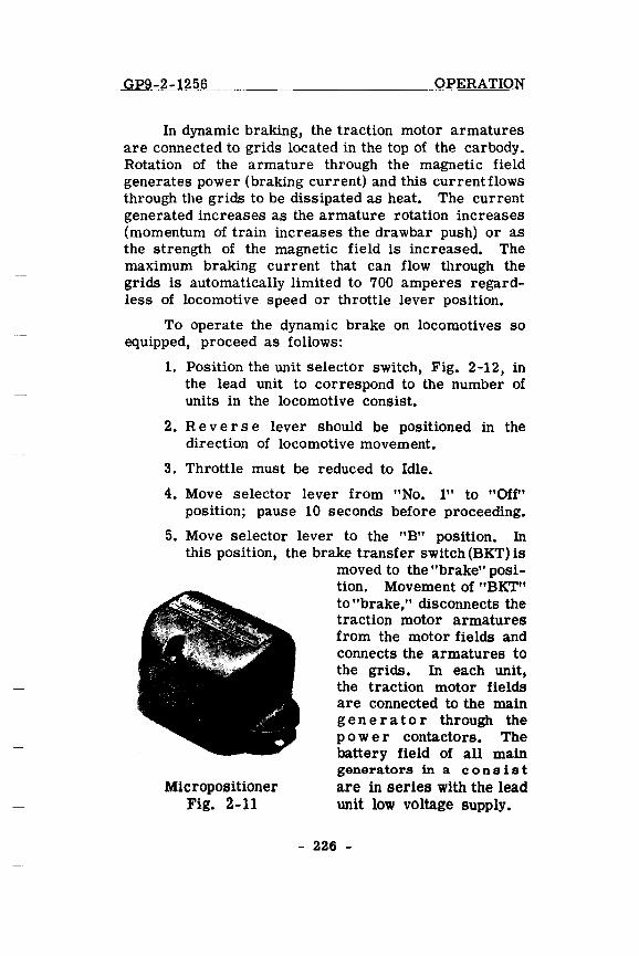
GP9-2-1256 OPERATION
In dynamic braking, the traction motor armatures are connected to grids located in the top of the car body . Rotation of the armature through the magnetic field generates power (braking current) and this current flows through the grids to be dissipated as heat. The current generated increases as the armature rotation increases (momentum of train increases the drawbar push) or as the strength of the magnetic field is increased. The maximum braking current that can flow through the grids is automatically limited to 700 amperes regardless of locomotive speed or throttle lever position.
To operate the dynamic brake on locomotives so equipped, proceed as follows:
1. Position the unit selector switch, Fig. 2-12, in the lead unit to correspond to the number of units in the locomotive consist.
2. Rever s e lever should be positioned in the direction of locomotive movement.
3. Throttle must be reduced to Idle.
4. Move selector lever from "No.1" to "Off" position; pause 10 seconds before proceeding.
5. Move selector lever to the "B" pOSition. In this position, the brake transfer switch (BKT) is
Micropositioner Fig. 2-11
moved to the "brake" position. Movement of "BKT" to "brake," disconnects the traction motor armatures from the motor fields and connects the armatures to the grids. In each unit, the traction motor fields are connected to the main g e n era tor through the power contactors. The battery field of all main generators in a con sis t are in series with the lead unit low voltage supply.
- 226 -
GP9-2-1256 OPERATION
6. After slack is bunched, the throttle lever may be moved to position the rheostat to give the desired amount of braking effort. (The speed of the diesel engine is increased from 275 RPM (Idle)' to 435 RPM automatically as the throttle handle is moved about 13° away from "Idle.")
7. Observe the braking amperage (braking effort) on the load indicating meter. The braking amperage is automatically limited to a maximum braking effort of 700 amperes regardless of locomotive speed or throttle handle position.
8. If maximum braking is desired, the throttle handle should be moved to the full 8th notch position. The throttle handle should always be moved S LOWLY to prevent a sudden surge of current ~ excess of the maximum brake current rating. Generally, if the throttle handle is moved slowly to the full braking pOSition, the brake current limiting regulator will limit the braking current to a maximum 700 amperes and no brake warning indication of excessive braking current will be given. However, if the brake warning light flashes on, movement of the throttle handle should be stopped until the light goes out.
If the light fails to go out after several seconds, move throttle handle back toward "Idle" position slowly until the light does go out. Mter the brake warning light goes out, the throttle handle may again be moved slowly toward the full 8th notch position.
9. When necessary, the automatic brake may be used in conjunction with the dynamic brake. However, the independent brake must be KEPT FULL Y RELEASED whenever the dynamic brake is in use, or the wheels may slide. As the speed decreases below 10 miles per hour the dynamic brake becomes less effective. When the speed further decreases, it is permissible
- 227 -
GP9-2-1256 OPERATION
to completely release the dynamic brake by placing the selector lever in the "OFF" or "No.1" position, applying the independent brake simultaneouslv to prevent the slack from running out.
NOTE: The most effective use of the dynamic brake is between 15 and 25 miles per hour depending on the gear ratio. Speed on grades should not be allowed to ''creep up" by careless handling of the brake, as this is a holding· brake and is not too effective in slowing down heavy trains on steep grades.
GP9 locomotives can be operated in dynamic braking coupled to older units that are not equipped with brake current limiting regulators. If all the units are of the same gear ratio, the unit having the lowest maximum brake current rating should be placed as the lead unit in the consist. The engineman can then operate and control the braking effort up to the limit of the unit having the lowest brake current rating, without overloading the dynamic brake system of a trailing unit. The locomotive consist MUST always be operated so as not to exceed the braking current of the unit having the lowest maximum brake current rating.
Units equipped with dynamic brake current limiting regulators can be operated in multiple with GP9 locomotives in dynamiC braking regardless of the gear ratio, or difference in the maximum brake current ratings.
Units not equipped with dynamic brake current limiting regulators and of different gear ratios will require special operating instructions when used in multiple with a GP9 locomotive in dynamic braking.
230 Dynamic Brake Selector Switch The dynamic brake unit selector switch, Fig. 2-12, located at the
- 228 -
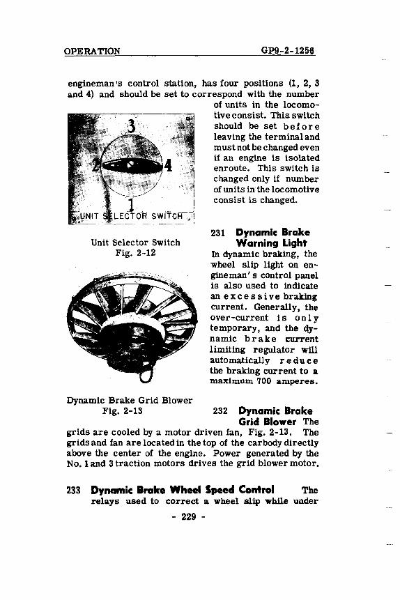
OPERATION G;e9-2-1256
engineman's control station, has four positions (1, 2, 3 and 4) and should be set to correspond with the number
Unit Selector Switch Fig. 2-12
Dynamic Brake Grid Blower
of units in the locomotive consist. This switch should be set be for e leaving the terminal and must not be changed even if an engine is isolated enroute. This switch is changed only if number of units in the locomotive consist is changed.
231 Dynamic Brake Warning Light
In dynamic braking, the wheel slip light on engineman' s control panel is also used to indicate an e x c e s s i v e braking current. Generally, the over-current is only temporary, and the dynamic bra k e current limiting regulator will automatically red u c e the braking current to a maximum 700 amperes.
Fig. 2-13 232 Dynamic Brake Grid Blower The
grids are cooled by a motor driven fan, Fig. 2-13. The grids and fan are located in the top of the car body directly above the center of the engine. Power generated by the No.1 and 3 traction motors drives the grid blower motor.
233 Dynamic: Brake Wheel Speed Control The relays used to correct a wheel slip while under
- 229 -
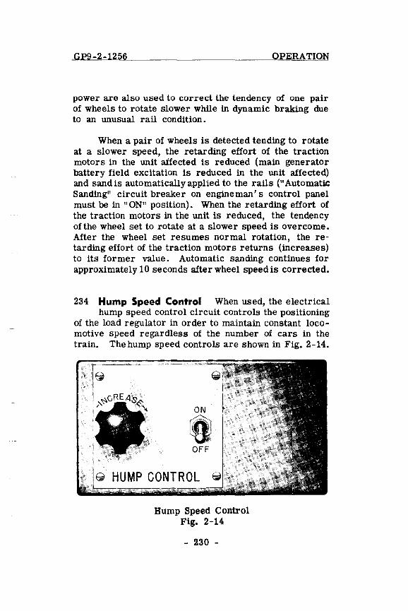
GP9-2-1256 OPERATION
power are also used to correct the tendency of one pair of wheels to rotate slower while in dynamic braking due to an unusual rail condition.
When a pair of wheels is detected tending to rotate at a slower speed, the retarding effort of the traction motors in the unit affected is reduced (main generator battery field excitation is reduced in the unit affected) and sand is automatically applied to the rails (" Automatic Sanding" circuit breaker on engine man' s control panel must be in "ON" position). When the retarding effort of the traction motors in the unit is reduced, the tendency of the wheel set to rotate at a slower speed is overcome. After the wheel set resumes normal rotation, the retarding effort of the traction motors returns (increases) to its former value. Automatic sanding continues for approximately 1 0 seconds after wheel speed is corrected.
234 Hump Speed Control When used, the electrical hump speed control circuit controls the positioning
of the load regulator in order to maintain constant locomotive speed regardless of the number of cars in the train. The hump speed controls are shown in Fig. 2-14.
ON
lft! OFF
@ HUMP CONTROL
Hump Speed Control Fig. 2-14
- 230 -
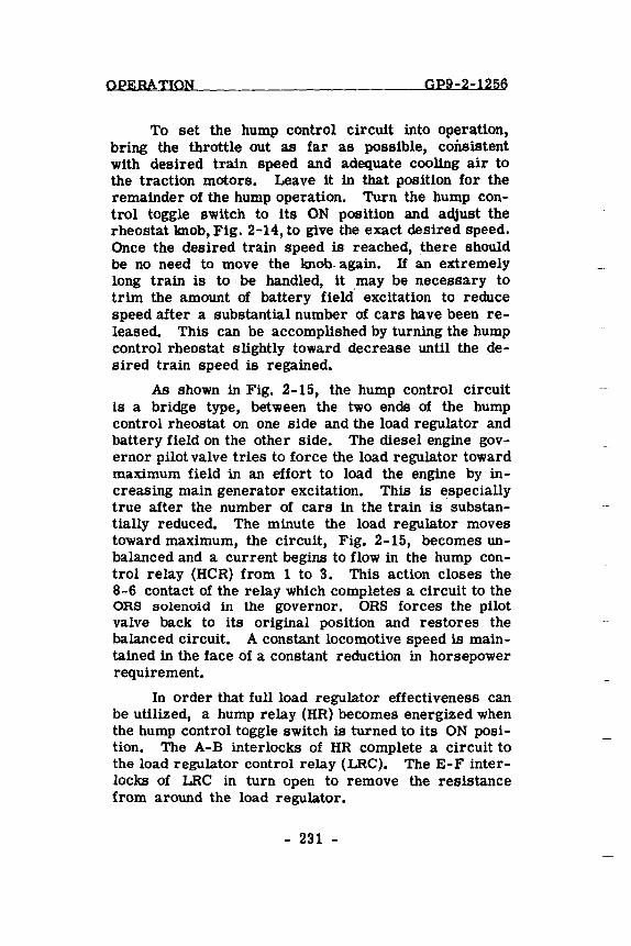
OPERATION GP9-2-1256
To set the hump control circuit into operation, bring the throttle out as far as possible, consistent with desired train speed and adequate cooling air to the traction motors. Leave it in that position for the remainder of the hump operation. Turn the hump control toggle switch to its ON pOSition and adjust the rheostat knob, Fig. 2-14, to give the exact desired speed. Once the desired train speed is reached, there should be no need to move the knob- again. If an extremely long train is to be handled, it may be necessary to trim the amount of battery field- excitation to reduce speed after a substantial number of cars have been released. This can be accomplished by turning the hump control rheostat slightly toward decrease until the desired train speed is regained.
As shown in Fig. 2-15, the hump COntrol circuit Ls a bridge type, between the two ends of the hump control rheostat on one side and the load regulator and battery field on the other side. The diesel engine governor pilot valve tries to force the load regulator toward maximum field in an effort to load the engine by increasing main generator excitation. This is especially true after the number of cars in the train is substantially reduced. The minute the load regulator moves toward maximum, the circuit, Fig. 2-15, becomes unbalanced and a current begins to flow in the hump control relay (HCR) from 1 to 3. This action closes the 8-6 contact of the relay which completes a circuit to the ORS solenoid in the governor. ORS forces the pilot valve back to its original position and restores the balanced circuit. A constant locomotive speed is maintained in the face of a constant reduction in horsepower requirement.
In order that full load regulator effectiveness can be utilized, a hump relay (HR) becomes energized when the hump control toggle switch is turned to its ON position. The A-B interlocks of HR complete a circuit to the load regulator control relay (LRC). The E-F interlocks of LRC in turn open to remove the resistance from around the load regulator.
- 231 -
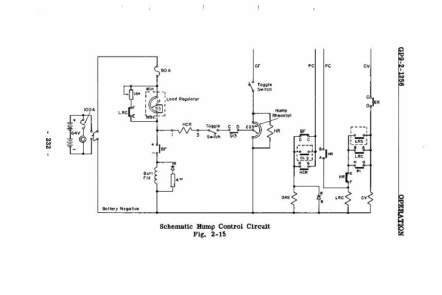
IDDA
Ballery Nega live
Ball_ Fld
3
Schematic Hump Control Circuit Fig. 2-15
PC
BF
D C
DRS
PC CV
Q)
C o IER
r- --, I ,
B IHR
A
HR
R LRC
B
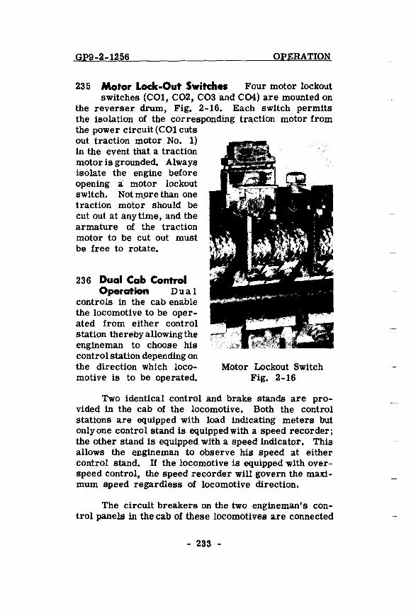
GP9-2-1256 OPERATION
235 Motor Lock-Out Switches Four motor lockout switches (COl, C02, C03 and C04) are mounted on
the reverser drum, Fig. 2-16. Each switch permits the isolation of the corresponding traction motor from the power circuit (COl cuts out traction motor No.1) in the event that a traction motor is grounded. Always isolate the engine before opening a motor lockout switch. Not m,ore than one traction motor should be cut out at anytime, and the armature of the traction motor to be cut out must be free to rotate.
236 Dual Cab Control Operation D u a I
controls in the cab enable the locomotive to be operated from either control station thereby allowing the engineman to choose his control station depending on the direction which locomotive is to be operated.
Motor Lockout Switch Fig. 2-16
Two identical control and brake stands are provided in the cab of the locomotive. Both the control stations are equipped with load indicating meters but only one control stand is equipped with a speed recorder; the other stand is equipped with a speed indicator. This allows the engine man to observe his speed at either control stand. H the locomotive is equipped with overspeed control, the speed recorder will govern the maximum speed regardless of locomotive direction.
The circuit breakers on the two engineman's control panels in the cab of these locomotives are connected
- 233 -
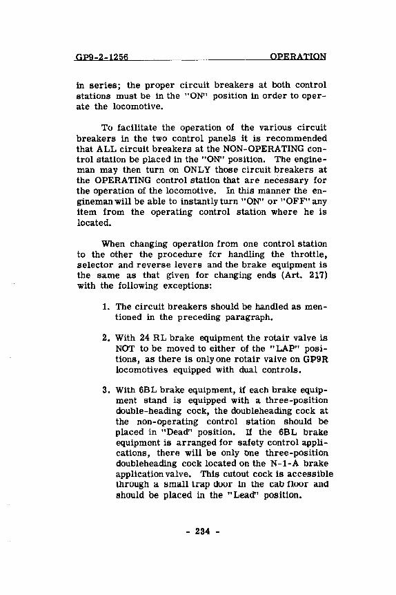
GP9-2-1256 OPERATION
in series; the proper circuit breakers at both control stations must be in the "ON" position in order to operate the locomotive.
To facilitate the operation of the various circuit breakers in the two control panels it is recommended that ALL circuit breakers at the NON-OPERATING control station be placed in the "ON" position. The engineman may then turn on ONLY those circuit breakers at the OPERATING control station that are necessary for the operation of the locomotive. In this manner the engineman will be able to instantly turn "ON" or "OFF" any item from the operating control station where he is located.
When changing operation from one control station to the other the procedure for handling the throttle, selector and reverse levers and the brake equipment is the same as that given for changing ends (Art. 217) with the following exceptions:
1. The circuit breakers should be handled as mentioned in the preceding paragraph.
2. With 24 RL brake equipment the rotair valve is NOT to be moved to either of the "LAP" positions, as there is only one rotair valve on GP9R locomotives equipped with dual controls.
3. With 6BL brake equipment, if each brake equipment stand is equipped with a three-position double-heading cock, the doubleheading cock at the non-operating control station should be placed in "Dead" position. If the 6BL brake equipment is arranged for safety control applications, there will be only tme three-position doubleheading cock located on the N-1-A brake application valve. This cutout cock is accessible through a small trap door in the cab floor and should be placed in the "Lead" position.
- 234 -
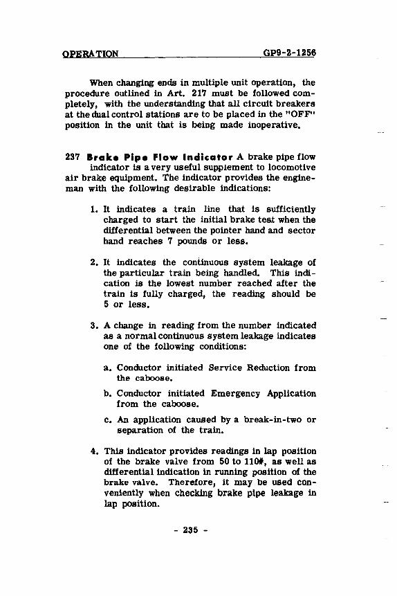
OPERATION GP9-2-1256
When changing ends in multiple unit operation, the procedure outlined in Art. 217 must be followed completely, with the understanding that all circuit breakers at the dual control stations are to be placed in the "OFF" position in the unit that is being made inoperative.
237 Brake Pipe Flow Indicator A brake pipe flow indicator is a very useful supplement to locomotive
air brake equipment. The indicator provides the engineman with the following desirable indications:
1. It indicates a train line that is sufficiently charged to start the initial brake teat when the differential between the pointer hand and sector hand reaches 7 pounds or less.
2. It indicates the continuous system leakage of the particular train being handled. This indication is the lowest number reached after the train is fully charged, the reading should be 5 or less.
3. A change in reading from the number indicated as a normal continuous system leakage indicates one of the following conditions:
a. Conductor initiated Service Reduction from the caboose.
b. Conductor initiated Emergency Application from the caboose.
c. An application caused by a break-in-two or separation of the train.
4. This indicator provides readings in lap position of the brake valve from 50 to 110*, as well as differential indication in running position of the brake valve. Therefore, it may be used conveniently when checking brake pipe leakage in lap position.
- 235 -
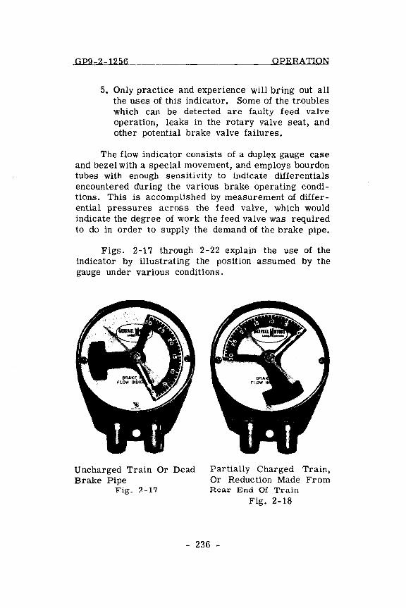
GP9-2-1256 OPERATION
5. Only practice and experience will bring out all the uses of this indicator. Some of the troubles which can be detected are faulty feed valve operation, leaks in the rotary valve seat, and other potential brake valve failures.
The flow indicator consists of a duplex gauge case and bezel with a special movement, and employs bourdon tubes with enough sensitivity to indicate differentials encountered during the various brake operating conditions. This is accomplished by measurement of differential pressures across the feed valve, which would indicate the degree of work the feed valve was required to do in order to supply the demand of the brake pipe.
Figs. 2-17 through 2-22 explain the use of the indicator by illustrating the position assumed by the gauge under various conditions.
Uncharged Train Or Dead Brake Pipe
Fig_ 2-17
Partially Charged Train, Or Reduction Made From Rear End Of Train
Fig. 2-18
- 236 -
OPERATION
Brakes Released And Train Charged, Ready For The Initial Brake Test
Fig. 2-19
Charged Brake Pipe With No Leakage
Fig. 2-21
GP9-2-1256
Continuous Leakage In A Charged Train
Fig. 2-20
After An Emergency Application
Fig. 2-22
- 237 -
GP9-3-154 TROUBLE SHOOTING
SECTION 3
LOCATION AND CORRECTION OF
DIFFICULTIES ON-THE-ROAD
This section provides a check list calling the operator's attention to the troubles which are most frequently encountered on the road, and which can be quickly remedied thereby eliminating many delays.
No attempt is made to explain general operation and functions of equipment on the locomotive. For such information refer to the other sections of this manual.
- 300 -
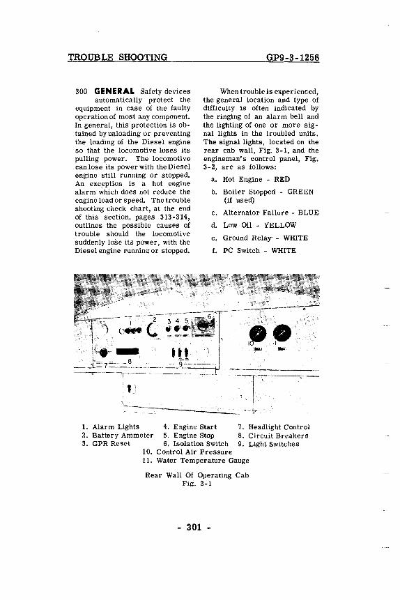
TROUBLE SHOOTING
300 GENERAL Safety devices automatically protect the
equipment in case of the faulty operation of most any component. In general, this protection is obtained by unloading or preventing the loading of the Diesel engine so that the locomotive loses its pulling power. The locomotive can lose its power with the Diesel engine still running or stopped. An exception is a hot engine alarm which does not reduce the engine load or speed. The trouble shooting check chart, at the end of this section, pages 313-314, outlines the possible causes of trouble should the locomotive suddenly lose its power, with the Diesel engine running or stopped.
ttl .::;:....::s,
GP9-3-1256
When trouble is experienced, the general location and type of difficulty is often indicated by the ringing of an alarm bell and the lighting of one or more signal lights in the troubled units. The signal lights, located on the rear cab wall, Fig. 3-1, and the engineman's control panel, Fig. 3-2, are as follows:
a. Hot Engine - RED
b. Boiler Stopped - GREEN (if used)
c. Alternator Failure - BLUE
d. Low Oil - YELLOW
e. Ground Relay' - WHITE
f. PC Switch - WHITE
--,------- 9= .. =_=-. =JI~-:--=;::;::::==::=:;;:::= '.1
1. Alarm Lights 4. Engine Start 2. Battery Ammeter 5. Engine Stop
7. Headlight Control B. Circuit Breakers 9. Light Switches 3. GPR Reset 6. Isolation Switch
10. Control Air Pressure 11. Water Temperature Gauge
Rear Wall Of Operating Cab Fig. 3-1
- 301 -
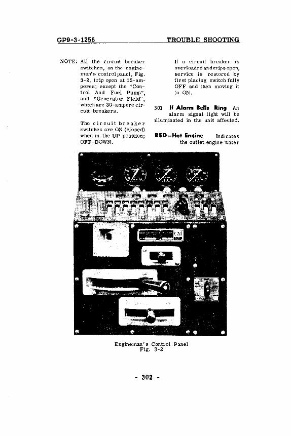
GP9-3-1256
NOTE: All the circuit breaker switches, on the engineman's control panel, Fig. 3-2, trip open at 15-amperes; except the "Control And Fuel Pump", and "Generator Field", which are 30-ampere circuit breakers.
The c i r cui t b rea k e r switches are ON (ciosed) when in the UP position; OFF-DOWN.
TROUBLE SHOOTING
If a circuit breaker is overloaded and trips open, service is restored by first placing switch fully OFF and then moving it to ON.
301 If Alarm Bells Ring An alarm signal light will be
illuminated in the unit affected.
RED-Hot Engine Indicates the outlet engine water
Engineman's Control Panel Fig. 3-2
- 302 -
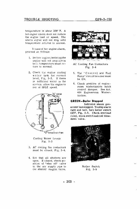
TROUBLE SHOOTING
temperature is about 2080 F. A hot engine alarm does not reduce the engine load or speed. The alarm signal will not stop until temperature returns to normal.
In case of hot engine alarm, proceed as follows:
1. Isolate engine; isolating the engine will not stop alarm bell; temperature must return to normal.
2. Check the engine cooling w ate r tank for correct level, Fig. 3-3. If there is sufficient water in the system, allow the engine to run at IDLE speed.
_. I
"Gil Valve Drain Pipe
Cooling Water Levels Fig. 3-3
3. AC cooling fan contactors must be closed, Fig. 3-4.
4. See that all shutters are open. If closed, check position of "shut off" valve in the air supply pipe to tlle IShulter magnet valve.
GP9-3-156
AC Cooling Fan Contactors Fig. 3-4
5. The "C 0 n t r 0 1 and Fuel Pump" circuit breaker must be ON.
6. Check position of engineroom winterization hatch control damper. See Art. 404 Engineroom Winterization.
GREEN-Boiler Stopped Indicates steam gen
erator has stopped. To stop alarm light and bell, turn boiler switch OFF, Fig. 3-5. Check overload relay, stack switch and coil blowdown valve.
Boiler Switch Fig. 3-5
- 303 -
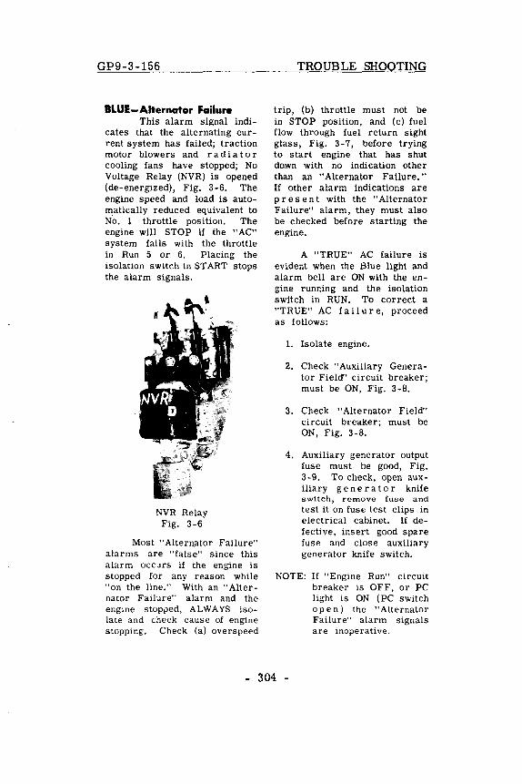
GP9-3-156
BLUE-Alternator Failure This alarm signal indi
cates that the alternating current system has failed; traction motor blowers and r a d i a tor cooling fans have stopped; No Voltage Relay (NVR) is opened (de-energized), Fig. 3-6. The engine speed and load is automatically reduced equivalent to No. 1 throttle position. The engine will STOP if the "AC" system fails with the throttle in Run 5 or 6. Placing the isolation switch in START stops the alarm signals.
NVR Relay Fig. 3-6
Most "Alternator Failure" alarms are "false" since this alarm occurs if the engine is stopped for any reason while "on the line." With an "Alternator Failure" alarm and the engine stopped, ALWAYS isolate and check cause of engine stopping. Check (a) overspeed
TROUBLE SHOOTING
trip, (b) throttle must not be in STOP position, and (c) fuel flow through fuel return sight glass, Fig. 3 -7, before trying to start engine that has shut down with no indication other than an "Alternator Failure." If other alarm indications are pre sen t with the "Alternator Failure" alarm, they must also be checked before starting the engine.
A "TRUE" AC failure is evident when the Blue light and alarm bell are ON with the engine runr.ing and the isolation switch in RUN. To correct a "TRUE" AC fa i I u r e, proceed as follows:
1. Isolate engine.
2. Check "Auxiliary Generator Field" circuit breaker; must be ON, Fig. 3-8.
3. Check "Alternator Field" circuit breaker; must be ON, Fig. 3-8.
4. Auxiliary generator output fuse must be good, Fig. 3-9. To check, open auxiliary g e n era tor knif e switch, remove fuse and test it on fuse test clips in electrical cabinet. If defective, insert good spare fuse and close auxiliary generator knife switch.
NOTE: If "Engine Run" circuit breaker is OFF, or PC light is ON (PC switch ope n) the "Alternator Failure" alarm signals are inoperative.
- 304 -
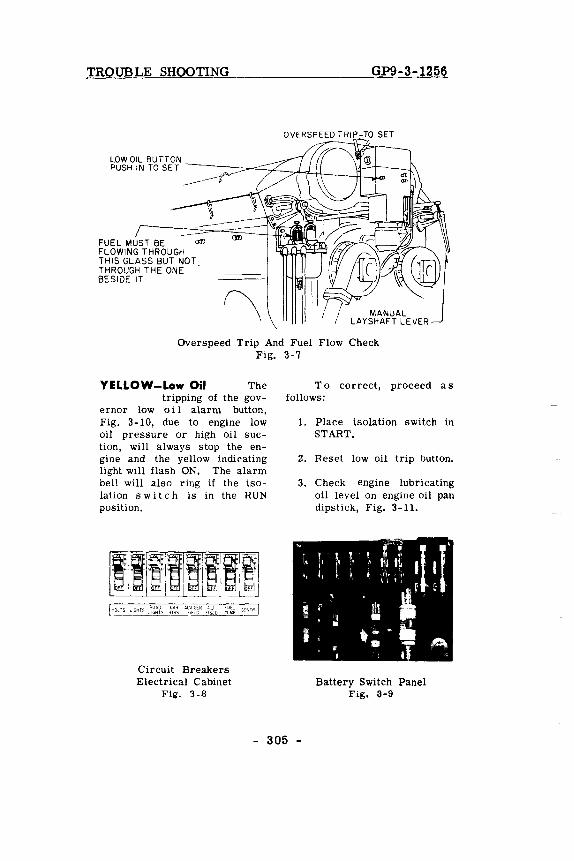
TROUBLE SHOOTING GP9-3-1256
OVERSPEED TRIP-TO SET 7'
LOW OIL BUTTON
PUSH I N TO SE T -~::;;::='-'=:7~7i'L1-4--Jt::J~
FUEL MUST BE <Jl'l FLOWING THROUGH THIS GLASS BUT NOT THROUGH THE ONE . BESIDE IT
Overspeed Trip And Fuel Flow Check Fig. 3-7
YELLOW-Low Oil The tripping of the gov
ernor low 0 i 1 alarm button, Fig. 3-10, due to engine low oil pressure or high oil suction, will always stop the engine and the yellow indicating light will flash ON. The alarm bell will also ring if the isolation s wit chis in the RUN position.
Circuit Breakers Electrical Cabinet
Fig. 3-8
To correct, proceed as follows:
1. Place isolation switch in START.
2. Reset low oil trip button.
3. Check engine lubricating oil level on engine oil pan dipstick, Fig. 3-11.
Battery Switch Panel Fig. 3-9
- 305 -
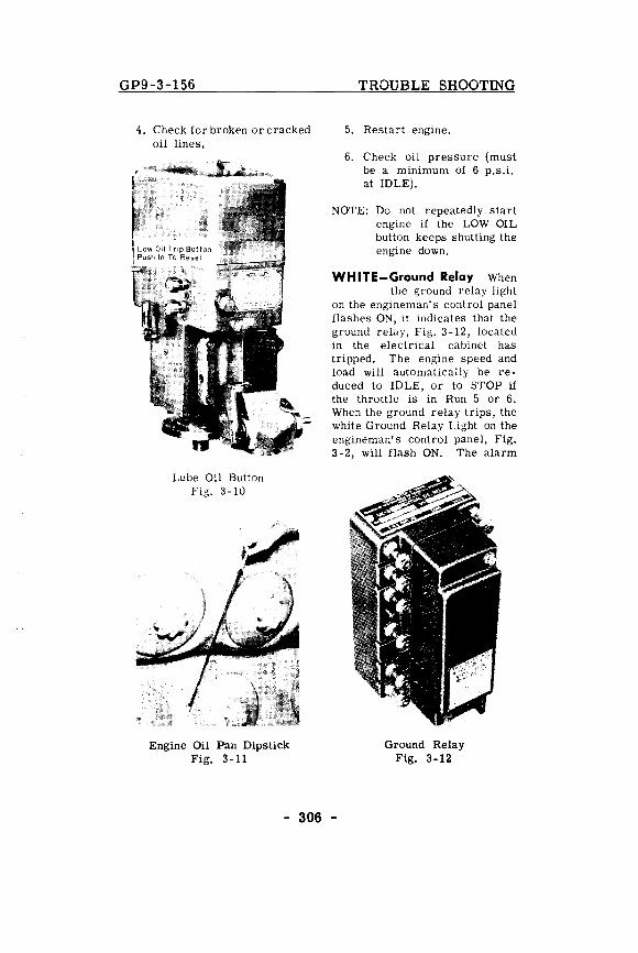
GP9-3-156
4. Check for broken or cracked oil lines.
Lube Oil Button Fig. 3-10
Engine Oil Pan Dipstick Fig. 3-11
TROUBLE SHOOTING
5. Restart engine.
6. Check oil pressure (must be a minimum of 6 p.s.i. at IDLE).
NOTE: Do not repeatedly start engine if the LOW OIL button keeps shutting the engine down.
WHITE-Ground Relay When the ground relay light
on the engineman's control panel flashes ON, it indicates that the ground relay, Fig. 3-12, located in the electrical cabinet has tripped. The engine speed and load will automatically be reduced to IDLE, or to STOP if the throttle is in Run 5 or 6. When the ground relay trips, the white Ground Relay Light on the engineman's control panel, Fig. 3-2, will flash ON. The alarm
Ground Relay Fig. 3-12
- 306 -
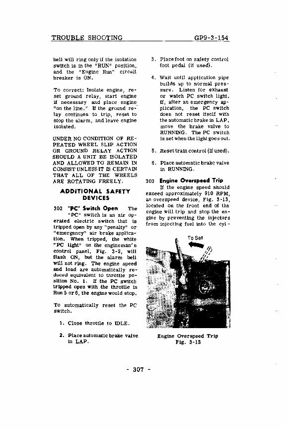
TROUBLE SHOOTING
bell will ring only if the isolation switch is in the "RUN" position, and the "Engine Run" circuit breaker is ON.
To correct: Isolate engine, reset ground relay, start engine if necessary and place engine "on the line." If the ground re-' lay continues to trip, reset to stop the alarm, and leave engine isolated.
UNDER NO CONDITION OF REPEATED WHEEL SLIP ACTION OR GROUND RELAY ACTION SHOULD A UNIT BE ISOLATED AND ALLOWED TO REMAIN IN CONSIST UNLESS IT IS CERTAIN THAT ALL OF THE WHEELS ARE ROTATING FREELY.
ADDITIONAL SAFETY DEVICES
302 "PC" Switch Open The "PC" switch is an air op
erated electric switch that is tripped open by any "penalty" or "emergency" air brake application. When tripped, the white "PC light" on the engineman's control panel, Fig. 3-2, will flash ON, but the alarm bell will not ring. The engine speed and load are automatically reduced equivalent to throttle position No. 1. If the PC switch tripped open with the throttle in Run 5 or 6, the engine would stop.
To automatically reset the PC switch.
1. Close throttle to IDLE.
2. Place automatic brake valve in LAP.
GP9-3-154
3. Place foot on safety control foot pedal (if used).
4. Wait until application pipe builds up to normal pressure. Listen for exhaust or watch PC switch light. If, after an emergency application, the PC switch doe s not re set itself with the automatic brake in LAP, move the brake valve to RUNNING. The PC SWitch is set when the light goes out.
5. Reset train control (if used).
6. Place automatic brake valve in RUNNING.
303 Engine Overspeed Trip If the engine speed should
exceed apprOXimately 910 RPM, an overspeed device, Fig. 3-13, located on the front end of the engine will trip and stop the engine by preventing the injectors from injecting fuel into the cyl-
Engine Overspeed Trip Fig. 3-13
- 307 -
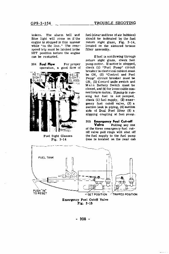
GP9-3-154
inders. The alarm bell and Blue light will corne on if the engine is stopped in this manner while "on the line." The overspeed trip must be latched in the SET position before the engine can be restarted.
304 Fuel Flow For proper operation, a good flow of
Fuel Sight Glasses Fig. 3-14
FUEL TANK
PUSH'IN' TO RESET
TROUBLE SHOOTING
fuel (clear and free of air bubbles) should be indicated by the fuel return sight glass, Fig. 3-14, located on the sintered bronze filter assembly.
Iffuel is not flowing through return sight glass, check fuel pump motor. If motor is stopped, check (1) "Fuel Pump" circuit breaker in electrical cabinet must be ON, (2) "Control and Fuel Pump" circuit breaker must be ON, (3) Control knife switch and M a in Battery Switch must be closed, and (4) for loose cable connectionstomotor. If pump is running but fuel is not pumped, check (1) fuel supply, (2) emergency fuel cutoff valve, (3) a suction leak in piping, (4) suction side of Dual Fuel filter (5) a slipping coupling at fuel pump.
305 Emergency Fuel Cut-oft Valve Pulling anyone
of the three emergency fuel cutoff valve pull rings will shut off the fuel supply to the fuel pump (one is located on the rear cab
Emergency Fuel Cutoff Valve Fig. 3-15
- 308 -

TROUBLE SHOOTING
wall behind the engineer, and one on each side of the locomotive near the fuel tank filler cap).
This valve is located inside a compartment on the lower front center of fuel tank. Action of the valve is as shown in Fig. 3-15. To reset, push in on the valve yoke "push rod" extension which can be reached from the right side of the unit. Pushing in on this push rod as far forward as possible will reopen the valve.
306 Control Air
GP9-3-154
2. No voltage relay (NVR). might be open (Blue light will be ON).
3. PC switch might be tripped.
4. "Control And Fuel Pump" circuit breaker on the engineman's con t r 0 I panel might be "Off."
5. "Engine Run" circuit breaker on the engineman's control panel might be "Off."
6. Isolation s w it c h might be in START.
Pressure For the satisfactory operation of the pneumatically operated contactors and switches used in the control circuit, the electrical control air pressure gauge on rear wall of the cab must indicate 90 ! 3 lbs. The pressure regulator, Fig. 3-16, is located in the electrical cabinet. To raise or lower pressure, change adjustment on top ofthe regulator. A drain cock is provided on bottom of
308 If The Engine Stops
Control Air Regulator Fig. 3-16
regulator for draining moisture.
CORRECTION OF DIFFICULTIES
30'1 If The Engine Goes to Idle
1. Groun d relay might be tripped.
- 309 -
1. Throttle might be in STOP position.
2. Low oil pressure button on the governor might be "out."
3. Engine 0 v e r s pee d device might have tripped.
4. No voltage relay (NVR) might have 0 pen e d with throttle in RUN 5 or 6.
5. Ground relay might have tripped with the throttle in RUN 5 or 6.
6. "Engine Run" circuit breaker on the engineman's control pan e I might have bee n tripped "Off," with the throttle in Run 5 or 6.
7. PC switch might have tripped with the throttle in Run 5 or 6.
8. "Fuel Pump" circuit breaker in the electrical cabinet might be "Off."
9. "Control and Fuel Pump" circuit breaker on the control panel might be "Off."
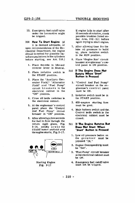
GP9-3-156
10. Emergencyfuelcutoffvalve under the locomotive might be tripped.
309 How To Start Ehgine (If it is deemed advisable, or
upon recommendation of the Mechanical Department, the engine should be tested for possible liquid accumulations in the cylinders before starting, see Art. 316.)
1. Place throttle in Idle and reverse lever in Neutral.
2. Place isolation switch in the START position.
3. Place the "Auxiliary Generator Field," "Alternator Field" and "Fuel Pump" c~cuit breakers in the electrical cabinet in the "ON" position.
4. Close all knife switches in the electrical cabinet.
5. At the engine man' s control panel place the "Control And Fuel Pump" circuit breaker in "ON" position.
6. After allowingafew seconds for fuel to flow through the return sight glass, Fig. 3-14, solidly press the START button andhold until the engine starts, Fig. 3-17.
ISOLATION SWITCH •
Starting Engine Fig. 3-11
TROUBLE SHOOTING
U engine fails to start after 15 seconds of rotation, check possible troubles listed under Arts. 310 - 311 before again trying to start engine.
7. After allowing time for the lube oil pressure to build up, place isolation switch in the RUN position.
S. Place "Engine Run" circuit breaker at engine man ' s control panel in ON position.
310 If The Engine Does Not Rotate When "Start" Bunon is Pressed
1. "Control And Fuel Pump" circuit breaker on the engineman's con t r 0 1 panel must be ON.
2. Isolation switch must be in the START position.
3. 400-ampere starting fuse must be good.
4. Main battery switch and the. Control knife switch in the electrical cabinet must be closed.
311 If The Engine Rotates But Does Not Start When "5rart" Bunon is Pressed
1. Low oil pressure button on the go v ern 0 r must be pr~ssed "IN."
2. Engine Overspeedtrip must be "Set".
3. ''Fuel Pump' circuit breaker in the electrical cabinet must be ON.
4. Emergency fuel cutoff valve mUiSt not be tripped.
- 310 -
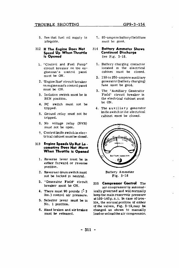
TROUBLE SHOOTING
5. See that fuel oil supply is adequate.
312 If The Engine Does Not Speed Up When Throttle is Opened
1. "Control and Fuel Pump" circuit breaker on the engineman's control panel must be ON.
2. ''Engine Run' circuit breaker on engineman's control panel must be ON.
3. Isolation switch must be in RUN position.
4. PC switch must not be tripped.
5. Ground relay must not be tripped.
6. No voltage relay (NVR) must not be open.
7. Control!mife switch in electrical cabinet must be closed.
313 Engine Speeds Up But La -comotive Does Not Move When Throttle is Opened
1. Reverse lever must be in either forward or reverse position.
2. Reverser drum switch must not be locked in neutral.
3. "Generator Field" circuit breaker must be ON.
4. There must 90 pounds (! 3 lbs.) control air pressure.
5. Selector lever must be in No. 1 position.
6. Hand brakes and air brakes must 00 released.
GP9-3-154
7. 80-ampere battery field fuse must be good.
314 Battery Ammeter Shows Continual Discharge See Fig. 3-18.
1. Battery charging contactor located in the electrical cabinet must be closed.
2. 150 or 250-ampere auxiliary generator (battery charging) fuse must be good.
3. The "Auxiliary Generator Field" circuit breaker in the electrical cabinet must be ON.
4. The a u xiI i a r y generator !miie switch in the electrical cabinet must be close.d.
Battery Ammeter Fig. 3-18
315 Compressor Control The air compressor is automat
ically governed and will normally keep the main reserVOir pressure at130-140p. s. i. In case oftrouble, the normal position of either of the valves, Fig. 3-19,may be changed as shown to manually load or unload the air compressor.
- 311 -
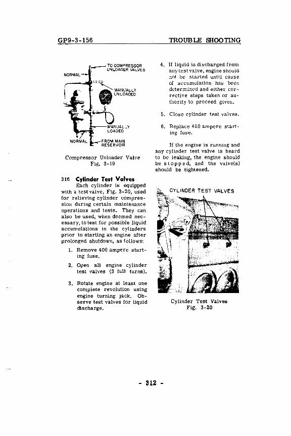
GP9-3-156
TO COMPRESSOR UNLOADER VALVES
Compressor Unloader Valve Fig. 3-19
316 Cylinder Test Valves Each cylinder is equipped
with a test valve, Fig. 3-20, used for relieving cylinder compression during certain maintenance operations and tests. They can also be used, when deemed necessary, to test for possible liquid accumulations in the cylinders prior to starting an engine after prolonged shutdown, as follows:
1. Remove 400 ampere starting fuse.
2. Open all engine cylinder test valves (3 full turns).
3. Rotate engine at least one complete revolution using engine turning jack. Observe test valves for liquid discharge.
TROUBLE SHOOTING
4. If liquid is discharged from any test valve, engine should not be started until cause of accumulation has been determined and either corrective steps taken or authority to proceed given.
5. Close cylinder test valves.
6. Replace 400 ampere starting fuse.
If the engine is running and any cylinder test valve is heard to be leaking, the engine should be s top p ed, and the valve(s) should be tightened.
Cylinder Test Valves Fig. 3-20
- 312 -
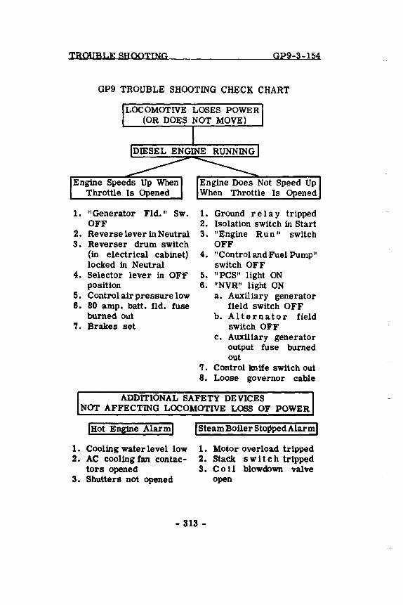
TROUBLE SHOOTING GP9-3-154
GP9 TROUBLE SHOOTING CHECK CHART
LOCOMOTIVE LOSES POWER (OR DOES NOT MOVE)
1. "Generator Fld." Sw. OFF
2. Reverse lever in Neutral 3. Reverser drum switch
(in electrical cabinet) locked in Neutral
4. Selector lever in OFF position
5. Control air pressure low 6. 80 amp. batt. fld. fuse
burned out 7. Brakes set
Engine Does Not Speed Up When Throttle Is Opened
1. Ground rei a y tripped 2. Isolation switch in Start 3. "Engine Run" switch
OFF 4. "Control and Fuel Pump"
switch OFF 5. "PCS" light ON 6. "NVR" light ON
a. Auxiliary generator field switch OFF
b. Alternator field switch OFF
c. Auxiliary generator output fuse burned out
7. Control knife switch out 8. Loose governor cable
ADDITIONAL SAFETY DEVICES NOT AFFECTING LOCOMOTIVE LOSS OF POWER
IHotEngine Alarml
1. Cooling water level low 2. AC cooling fan contac
tors opened 3. Shutters not opened
ISteamBoiler Sto~pedAlarml
1. Motor overload tripped 2. Stack s wit c h tripped 3. Co 11 blowdown valve
open
- 313 -
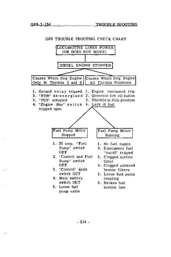
GP9-3-154 TROUBLE SHOOTING
GP9 TROUBLE SHOOTING CHECK CHART
LOCOMOTIVE LOSES POWER (OR DOES NOT MOVE)
Causes Which Stop Engine Onl In Throttle 5 and 6
Caus'es Which Stop Engine All Throttle Positions
1. Ground reI a y tripped 1. Engine overspeed trip 2. "NVR" de-energized 2. Governor low oil button 3. "PCS" actuated 3. Throttle in Stop position 4. "Engine Run" switch 4. Lack of fuel
tripped open
1. 30 amp. "Fuel 1. No fuel supply Pump" switch 2. Emergency fuel OFF "cutoff" tripped
2. "Control and Fuel 3 . Clogged suction Pump" switch filter OFF 4. Clogged sintered
3. "Control" knife bronze filters switch OUT 5. Loose fuel pump
4. Main battery coupling switch OUT 6. Broken fuel
5. Loose fuel suction line pump cable
- 314 -
GP9-4-156 SYSTEMS
SECTION 4
COOLING, LUBRICATING OIL, FUEL OIL AND AIR SYSTEMS
COOLING SYSTEM
A schematic flow diagram of the engine cooling system is shown in Fig. 4-1. Water is circulated through the cooling system by two centrifugal type pumps mounted on the front end of the engine. Water, drawn from the engine cooling water tank and oil cooler by the pumps, is forced through the engine and then through the radiator where it is cooled. After leaving the radiator, the water flows through the oil cooler and then to the suction side of the pumps where the cycle is repeated.
The radiator is made up of two banks; each bank consists of five radiator sections. Water leaving the engine and entering the radiator is divided between the right and left bank radiator sections. In each bank, two radiator sections are located at the cab end of the long hood, and three radiator sections are located at the opposite end of the long hood. The front and rear radiator sections of each bank are connected together by a water manifold.
Flow of cooling air through the finned radiator sections is controlled by shutters and four AC driven cooling fans. The operation of the fans and shutters is automatic. When the fans are operating, air flows up through the radiator sections and is discharged from the roof of the carbody.
The four AC driven cooling fans are mounted in the roof of the long hood above the radiator sections. Two fans control the cooling air through the cab end radiator sections of each bank and two fans mounted at the other end of the long hood control the cooling air through the rear banks of radiator sections. The fans are numbered one to four, beginning with the # 1 fan located nearest to the cab end of the long hood.
- 400 -
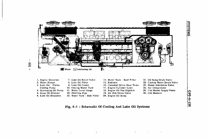
.Waler
1. Engine Governor 7. Lube Oil Relief Valve 14. Water Tank - Roof Filler 2l. Oil Sump Drain Valve 2. Water Pumps 8. Lube Oil Filter 15. Radiator 22. Cooling Water Drain Valve 3. Lube Oil - Piston 9. Lube Oil Cooler 16. Camshaft Drive Gear Train 23. Steam Admission Valve
Cooling Pump 10. Cooling Water Tank 17. Engine Cylinder Liner 24. Air Compressor 4. Scavenging Oil Pump 11. Water Level Gauge 18. Engine Oil Pan Dipstick 25. Cab Heater Supply Valve 5. Sump Oil Strainer 12. Overflow Pipe 19. Air Box Drain Valve 26. Cab Heaters 6. Lube Oil Strainers 13. Water Tank - Side Filler 20. Engine Oil Sump
Fig. 4 -1 - Schematic Of Cooling And Lube Oil Systems
o :g I ~ I ....
c.n 0)
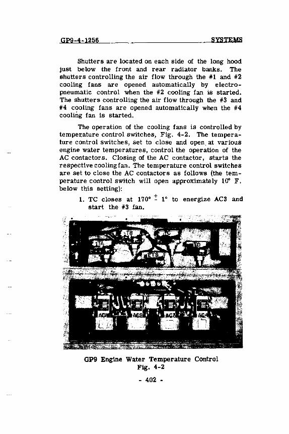
Gpg-4-1256 SysTEMS
Shutters are located on each side of the long hood just below the front and rear radiator banks. The shutters controlling the air flow through the in and #2 cooling fans are opened automatically by electropneumatic control when the #2 cooling fan is started. The shutters controlling the air flow through the #3 and #4 cooling fans are opened automatically when the #4 cooling fan is started.
The operation of the cooling fans is controlled by tempe:x:ature control switches, Fig. 4-2. The temperature control switches, set to close and open, at various engine water temperatures, control the operation of the AC contactors. Closing of the AC contactor, starts the respective cooling fan. The temperature control switches are set to close the AC contactors as follows (the temperature control switch will open approximately 10" F. below this setting):
+ 1. TC closes at 1700 - 10 to energize AC3 and
start the #3 fan.
GP9 Engine Water Temperature Control Fig. 4-2
- 402 -
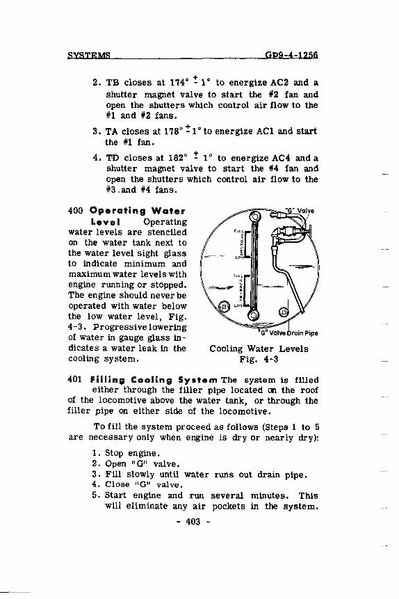
SYSTEMS Gp9-4-1256
+ 2. TB closes at 1'740 - 10 to energize AC2 and a
shutter magnet valve to start the #2 fan and open the shutters which control air flow to the #1 and #2 fans.
+ 3. TA closes at 1780 _1 0 to energize ACI and start the #1 fan.
+ 4. T·D closes at 182 0 - 10 to energize AC4 and a
shutter magnet valve to start the #4 fan and open the shutters which control air flow to the #3 ,and #4 fans.
400 Operating Water Level Operating
water levels are stenciled on the water tank next to the water level sight glass to indicate minimum and maximum water levels with engme running or stopped. The engine should never be operated with water below the low water level, Fig. 4-3. Progressive lowering of water in gauge glass indicates a water leak in the cooling system.
"G" Valve Drain Pipe
Cooling Water Levels Fig. 4-3
401 Filling Cooling System The system is filled either through the filler pipe located on the roof
of the locomotive above the water tank, or through the filler pipe on either side of the locomotive.
To fill the system proceed as follows (Steps 1 to 5 are necessary only when engine is dry or nearly dry):
1. Stop engine. 2. Open "G" valve. 3. Fill slowly until water runs out drain pipe. 4. Close "G" valve. 5. Start engine and run several minutes. This
will eliminate any air pockets in the system.
- 403 -
GP9-4-1256 SYSTEMS
6. Stop engine and open "G" valve. 7. Add water until it· runs out "G" valve drain pipe. 8. Close "G" valve.
If the cooling system of a hot engine has been drained, do not refill immediately with cold water. If this is done, the sudden change in temperature might crack or warp the cylinder liners and heads.
CAUTION: 1. Do not attempt to fill the cooling system through the drain pipe located underneath the locomotive.
2. The system should not be filled above the maximum water level indicated on the water tank to prevent:
a. Freezing of radiators in winter when engine is shut down.
b. Loss of rust inhibitor when draining back to "G" valve level.
402 Draining Cooling System The entire COOling system can be drained through the drain valve on
the floor in front of the engine, with the exception of the water trapped in the water pump on the right hand side of the engine. To drain the right hand water pump, open the drain on the bottom of the water pump housing.
403 Cab Heating and Ventilating Cab heaters are complete with defroster and fresh air ventilators,
Fig. 4-4. Fresh air is taken in through a louver in the cab wall and is controlled by a fresh air damper within the heater.
Controlled by a rheostat type switch, a 1/6th HP variable speed fan motor draws in fresh air or recirculates cab air. The fan fOl"ces air through a hot water radiator and exhausts the heated air out onto the cab floor.
- 404 -
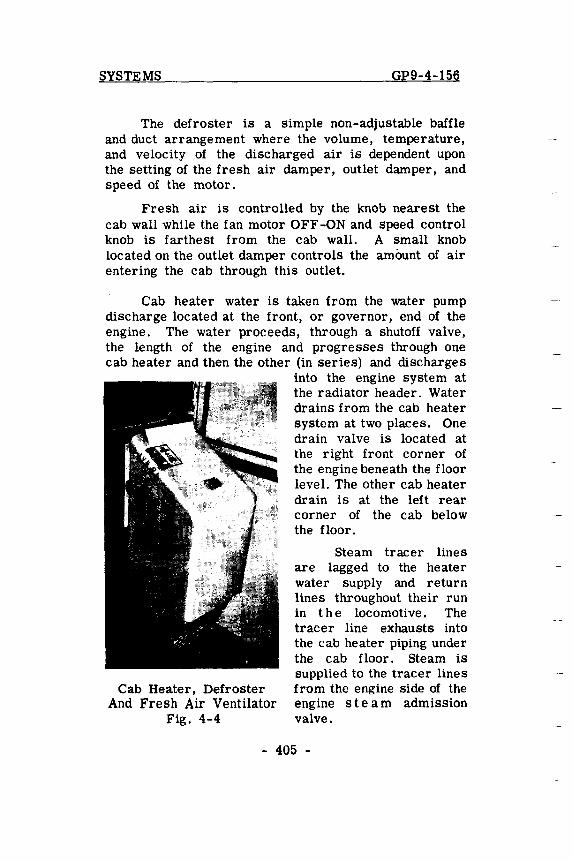
SYSTEMS GP9-4-156
The defroster is a simple non-adjustable baffle and duct arrangement where the volume, temperature, and velocity of the discharged air is dependent upon the setting of the fresh air damper, outlet damper, and speed of the motor.
Fresh air is controlled by the knob nearest the cab wall while the fan motor OFF-ON and speed control knob is farthest from the cab wall. A small knob located on the outlet damper controls the amount of air entering the cab through this outlet.
Cab heater water is taken from the water pump discharge located at the front, or governor, end of the engine. The water proceeds, through a shutoff valve, the length of the engine and progresses through one cab heater and then the other (in series) and discharges
Cab Heater, Defroster And Fresh Air Ventilator
Fig. 4-4
into the engine system at the radiator header. Water drains from the cab heater system at two places. One drain valve is located at the right front corner of the engine beneath the floor level. The other cab heater drain is at the left rear corner of the cab below the floor.
Steam tracer lines are lagged to the heater water supply and return lines throughout their run in the locomoti ve. The tracer line exhausts into the cab heater piping under the cab floor. Steam is supplied to the tracer lines from the engine side of the engine s tea m admission valve.
- 405 -
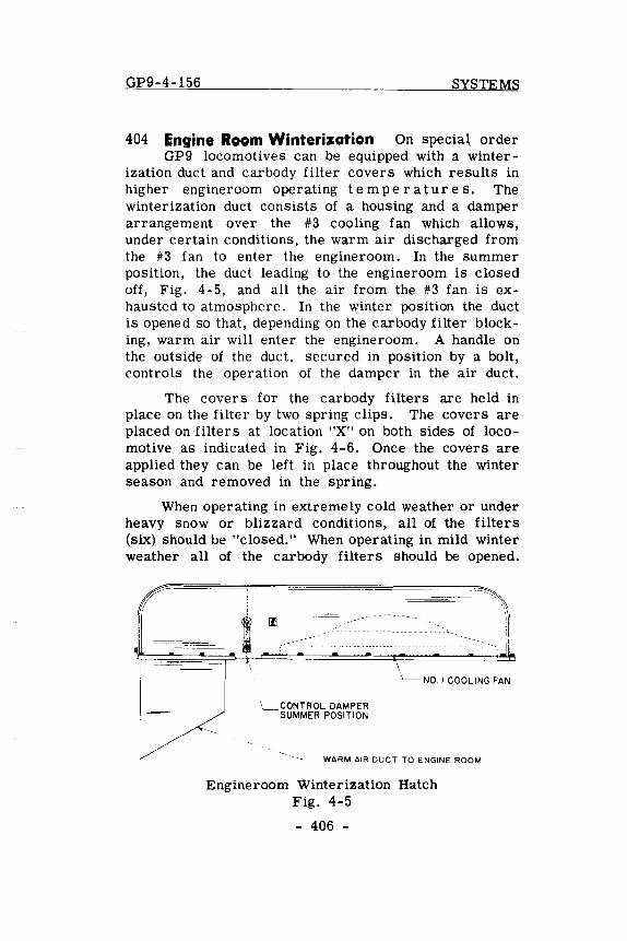
GP9-4-156 SYSTEMS
404 Engine Room Winterization On specia~ order GP9 locomotives can be equipped with a winter
ization duct and carbody filter covers which results in higher engineroom operating t em per at u res. The winterization duct consists of a housing and a damper arrangement over the #3 cooling fan which allows, under certain conditions, the warm air discharged from the #3 fan to enter the engineroom. In the summer position, the duct leading to the engineroom is closed off, Fig. 4-5, and all the air from the #3 fan is exhausted to atmosphere. In the winter position the duct is opened so that, depending on the carbody filter blocking, warm air will enter the engineroom. A handle on the outside of the duct, secured in position by a bolt, controls the operation of the damper in the air duct.
The covers for the carbody filters are held in place on the filter by two spring clips. The covers are placed on filters at location "X" on both sides of locomotive as indicated in Fig. 4-6. Once the covers are applied they can be left in place throughout the winter season and removed in the spring.
When operating in extremely cold weather or under heavy Snow or blizzard conditions, all of the filters (six) should be "closed." When operating in mild winter weather all of the carbody filters should be opened.
\ __ CONTROL DAMPER SUMMER POSITION
\ '--- NO. I COOLING FAN
-~-WARM AIR DUCT TO ENGINE ROOM
Engineroom Winterization Hatch Fig. 4-5
- 406 -
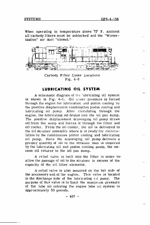
SYSTEMS GP9-4-156
When operating in temperature above 75° F. ambient all carbody filters must be unblocked and the "Winterization" air duct "closed."
Carbody Filter Cover Locations Fig. 4-6
LUBRICATING OIL SYSTEM
A schematic diagram of the lubricating oil system is shown in Fig. 4-1. Oil under pressure is forced through the engine for lubrication and piston cooling by the positive displacement combination piston cooling and lubricating oil pump. After circulating through the engine, the lubricating oil drains into the oil pan sump. The positive displacement scavenging oil pump draws oil from the sump and forces it through the filter and oil cooler. From the oil cooler, the oil is delivered to the oil strainer assembly where it is ready for recirculation by the combination piston cooling and lubricating oil rump. Since the scavenging oil pump delivers a greater quantity of oil to the strainer than is required by the lubricating oil and piston cooling pump, the excess oil returns to the oil pan sump.
A relief valve is built into the filter in order to' allow the passage of oil to the strainer in excess of the capacity of the oil filter elements.
A relief valve is also mounted on the left side of the accessory end of the engine. This valve is located in the discharge side of the lubricating oil pump. The purpose of this valve is to limit the maximum pressure of the lube oil entering the engine lube 011 system to approximately 50 pounds.
- 407 -
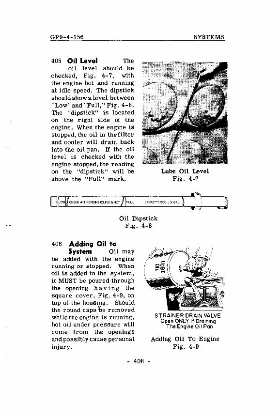
GP9-4-156
405 Oil Level The oil level should be
checked, Fig. 4-7, with the engine hot and running at idle speed. The dipstick should show a level between "Low" and "Full," Fig. 4-8. The "dipstick" is located on the right side of the engine. When the engine is stopped, the oil in the filter and cooler will drain back into the oil pan. If the oil level is checked with the engine stopped, the reading on the "dipstick" will be above the "Full" mark.
o LOW CHECK WITH ENGINE IOLING 6 HOT FULL
SYSTEMS
Lube Oil Level Fig. 4-7
CAPACITY 200 u.s GAL
Oil Dipstick Fig. 4-8
406 Adding Oil to System Oil may
be added with the engine running or stopped. When oil is added to the system, it MUST be poured through the opening h a vi n g the square cover, Fig. 4-9, on top of the hou,fjing. Should the round caps 'be removed while the engine is running, hot oil under pressure will come from the openings and possibly cause personal injury.
- 408 -
STRAINER DRAIN VALVE Open ONLY If Draining
The Engine Oil Pan
Adding Oil To Engine Fig. 4-9
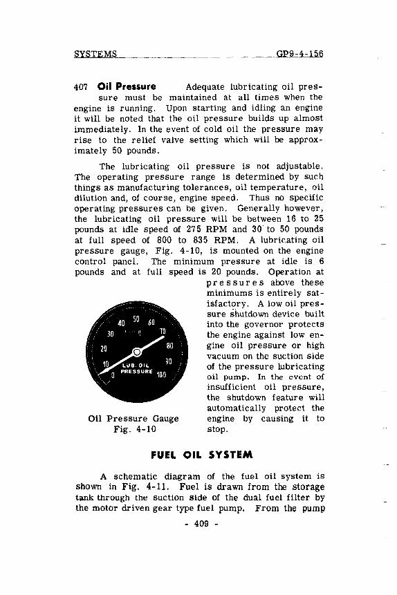
SYSTEMS GP9-4-156
407 Oil Pressure Adequate lubricating oil pres-sure must be maintained at all times when the
engine is running. Upon starting and idling an engine it will be noted that the oil pressure builds up almost immediately. In the event of cold oil the pressure may rise to the relief valve setting which will be approximately 50 pounds.
The lubricating oil pressure is not adjustable. The operating pressure range is determined by such things as manufacturing tolerances, oil temperature, oil dilution and, of course, engine speed. Thus no specific operating pressures can be given. Generally however, the lubricating oil pressure will be between 16 to 25 pounds at idle speed of 275 RPM and 30 to 50 pounds at full speed of 800 to 835 RPM. A lubricating oil pressure gauge, Fig. 4-10, is mounted on the engine control panel. The minimum pressure at idle is 6 pounds and at full speed is 20 pounds. Operation at
Oil Pressure Gauge Fig. 4-10
pre s sur e s above these minimums is entirely satisfactory. A low oil pressure shutdown device built into the governor protects the engine against low engine oil pressure or high vacuum on the suction side of the pressure lubricating oil pump. In the event of insufficient oil pressure, the shutdown feature will automatically protect the engine by causing it to stop.
FUEL OIL SYSTEM
A schematic diagram of the fuel oil system is shown in Fig. 4-11. Fuel is drawn from the storage tank through the suction side of the dual fuel filter by the motor driven gear type fuel pump. From the pump
- 409 -
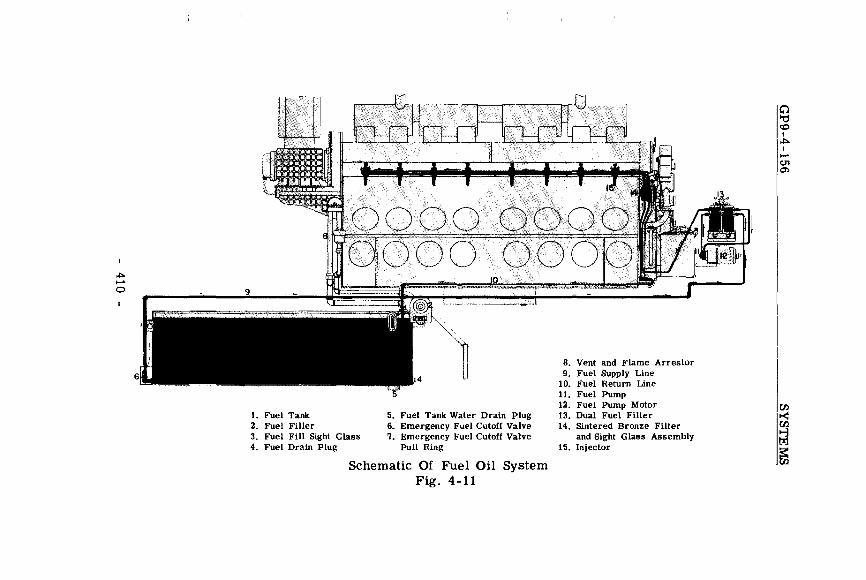
~ ...... o
1. Fuel Tank 5. Fuel Tank Water Drain Plug 2. Fuel Filler 6. Emergency Fuel Cutoff Valve 3. Fuel Fill Sight Glass 7. Emergency Fuel Cutoff Valve
Pull Ring 4. Fuel Drain Plug
Schematic Of Fuel Oil System Fig. 4-11
8. Vent and Flame Arrestor 9. Fuel Supply Line
10. Fuel Return Line 11. Fuel Pump 12. Fuel Pump Motor 13. Dual Fuel Filter 14. Sintered Bronze Filter
and Sight Glass Assembly 15. Injector
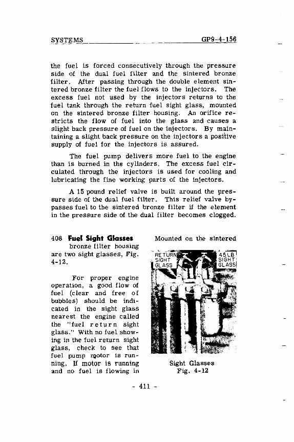
SYSTEMS GP9-4-156
the fuel is forced consecutively through the pressure side of the dual fuel filter and the sintered bronze filter. After passing through the double element sintered bronze filter the fuel flows to the injectors. The excess fuel not used by the injectors returns to the fuel tank through the return fuel sight glass, mounted on the sintered bronze filter housing. An orifice restricts the flow of fuel into the glass and causes a slight back pressure of fuel on the injectors. By maintaining a slight back pressure on the injectors a pOSitive supply of fuel for the injectors is assured.
The fuel pump delivers more fuel to the engine than is burned in the cylinders. The excess fuel circulated through the injectors is used for cooling and lubricating the fine working parts of the injectors.
A 15 pound relief valve is built around the pressure side of the dual fuel filter. This relief valve bypasses fuel to the sintered bronze filter if the element in the pressure Side of the dual filter becomes clogged.
408 Fuel Sight Glasses bronze filter housing
are two sight glasses, Fig. 4-12.
For proper engine operation, a good flow of fuel (clear and free of bubbles) should be indicated in the sight glass nearest the engine called the "fuel return sight glass." With no fuel showing in the fuel return sight glass, check to see that fuel pump ~otor is running. If motor is running and no fuel is flowing in
Mounted on the sintered
Sight Glasses Fig. 4-12
- 411 -
GP9-4-156 SYSTEMS
return sight glass, check (a) fuel supply in fuel tank (b) position of emergency cutoff valve (c) clogged suction filter (d) suction leak in piping between tank and pump or (e) broken or slipping coupling at fuel pump.
If fuel pump motor is stopped, check (a) "Control and Fuel Pump" circuit breaker must be "ON" (b) "Fuel Pump" circuit breaker in electrical cabinet must be "ON" (c) control knife switch must be closed (d) main battery switch must be closed or (e) loose fuel pump motor cable connection.
The sintered bronze filter is also equipped with a 45-pound relief valve and sight glass, Fig. 4-12. This sight glass is referred to as the "45-pound sight glass" and is normally empty. When more than a trickle of fuel is seen in the 45-pound sight glass, it indicates that the relief valve is open. Fuel will pass through the 45-pound sight glass and relief valve to by-pass the engine and return to the fuel tank in case the sintered bronze filter becomes clogged.
409 Filling Fuel Tanks The fuel tank can be filled from either side of the locomotive. A short sight
level gauge is located next to each fuel filler. This fuel gauge indicates the fuel level from the top to about 4-1/2" below the top of the tank and should be observed while filling the tank to prevent overfilling. 00 NOT HANDLE FUEL OIL NEAR AN OPEN FLAME.
410 Fuel Gauge The basic fuel capacity is 900 gallons. Full length sight level gauges are located
on each side of the front end of the fuel tanle These gauges indicate the level of fuel in the tank below the low level of the short fuel filler gauge.
- 412 -
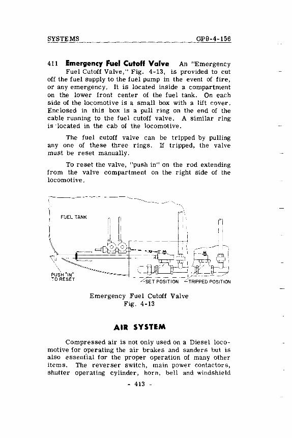
SYSTEMS GP9-4-156
411 Emergency Fuel Cutoff Valve An "Emergency Fuel Cutoff Valve," Fig. 4-13, is provided to cut
off the fuel supply to the fuel pump in the event of fire, or any emergency. It is located inside a compartment on the lower front center of the fuel tank. On each side of the locomotive is a small box with a lift cover. Enclosed in this box is a pull ring on the end of the cable running to the fuel cutoff valve. A similar ring is 'located in the cab of the locomotive.
The fuel cutoff valve can be tripped by pulling anyone of these three rings. If tripped, the valve must be reset manually.
To reset the valve, "push in" on the rod extending from the valve compartment on the right side of the locomotive.
FUEL TANK
\
P~~"IN" TO RESET Lsn POSITION
Emergency Fuel Cutoff Valve Fig. 4-13
AIR SYSTEM
Compressed air is not only used on a Diesel locomotive for operating the air brakes and sanders but is also essent'ial for the proper operation of many other items. The reverser switch, main power contactors, shutter operating cylinder, horn, bell and windshield
- 413 -
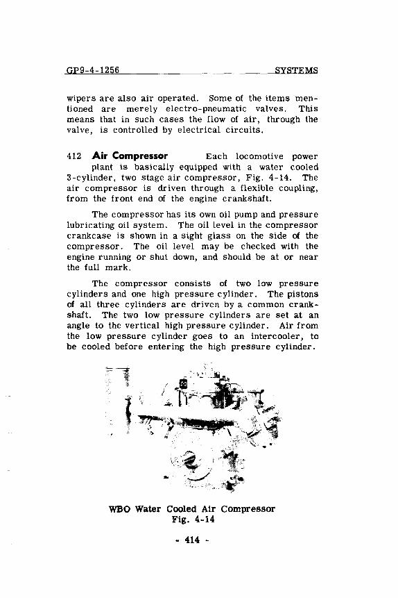
GP9-4-1256 SYSTEMS
wipers are also air operated. Some of the items mentioned are merely electro-pneumatic valves. This means that in such cases the flow of air, through the val ve, is controlled by electrical circuits.
412 Air Compressor Each locomotive power plant is baSically equipped with a water cooled
3-cylinder, two stage air compressor, Fig. 4-14. The air compressor is driven through a flexible coupling, from the front end of the engine crankshaft.
The compressor has its own oil pump and pressure lubricating oil system. The oil level in the compressor crankcase is shown in a sight glass on the side of the compressor. The oil level may be checked with the engine running or shut down, and should be at or near the full mark.
The compressor consists of two low pressure cylinders and one high pressure cylinder. The pistons of all three cylinders are driven by a common crankshaft. The two low pressure cylinders are set at an angle to the vertical high pressure cylinder. Air from the low pressure cylinder goes to an intercooler, to be cooled before entering the high pressure cylinder.
~.J-
, ,,/
:;Y
WBO Water Cooled Air Compressor Fig. 4-14
- 414 -
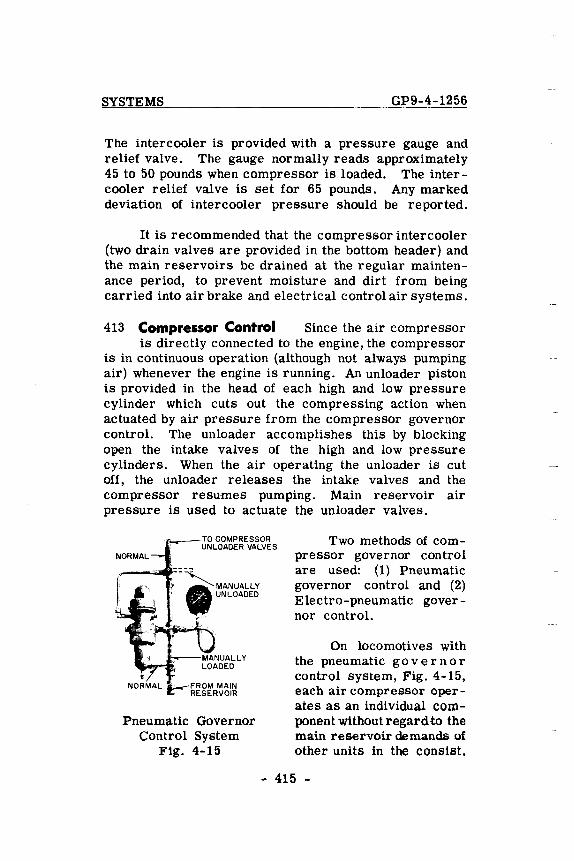
SYSTEMS GP9-4-1256
The intercooler is provided with a pressure gauge and relief valve. The gauge normally reads approximately 45 to 50 pounds when compressor is loaded. The intercooler relief valve is set for 65 pounds. Any marked deviation of intercooler pressure should be reported.
It is recommended that the compressor intercooler (two drain valves are provided in the bottom header) and the main reservoirs be drained at the regular maintenance period, to prevent moisture and dirt from being carried into air brake and electrical control air systems.
413 Compressor Control Since the air compressor is directly connected to the engine, the compressor
is in continuous operation (although not always pumping air) whenever the engine is running. An unloader piston is provided in the head of each high and low pressure cylinder which cuts out the compreSSing action when actuated by air pressure from the compressor governor control. The unloader accomplishes this by blocking open the intake valves of the high and low pressure cylinders. When the air operating the unloader is cut off, the unloader releases the intake valves and the compressor resumes pumping. Main reservoir air pressure is used to actuate the unloader valves.
Pneumatic Governor Control System
Fig. 4-15
Two methods of compressor governor control are used: (1) Pneumatic governor control and (2) Electro-pneumatic governor control.
On locomotives with the pneumatic go v ern 0 r control system, Fig. 4-15, each air compressor operates as an individual component without regard to the main reservoir demands of other units in the consist.
- 415 -
-=G=P--=-9_-4-=---=1=-=5-=-6 _______ ~ ________ j)_Y_ST_EM~
When the main reservoir air pressure reaches 140 p,::)Unds, the governor "cuts out" the air compressor by admitting air to unloader valves. Admitting air to the unloader valve will hold the intake valves open stopping the compressing aclion. The compressor remains unloaded unlil the main reservoir pressure falls to 130 pounds. The governor then "cuts in" the air compressor by stopping the air supply to the unloader valves, releasing the intake valves and the compressor resumes pumping.
If all the units of a locomotive consist are equipped with the electro-pneumatic system of compressor governor control, Fig. 4-16, the electrical arrangement is such that all compressors in the locomotive are synchronized to pump air into their respective main reservoirs when the main reservoir pressure in anyone unit drops to 130 pounds. When the air pressure in all reservoirs reaches, 140 pounds, the compressors will unload. Each unit is equipped with a compressor control switch (eeS) actuated by main reservoir pressure, a compressor control magnet valve and a compressor relay (eR). A compressor control wire (ee) runs throughout the locomotive and connects the compressor relays in each unit in parallel.
This electro-pneumatic governor control is located on the equipment rack supporting the water supply tank, oil cooler and Michiana filter assemblies, Fig. 4-17. The compressor control switch may be considered to be a single-pole double-throw switch that is thrown to the "loaded" position when the main reservoir pressure drops to 130 pounds, or to the "unloaded" position when the main reservoir pressure reaches 140 pounds. In the unloaded position the ees causes the compressor control magnet valve to be energized, allowing air to pass through the valve to the compressor unloader pistons stopping the compressing action. In the loaded position the ees breaks the circuit to compressor control magnet valve in that unit and causes current to flow through the ee wire energizing all the eR relays.
- 416 -
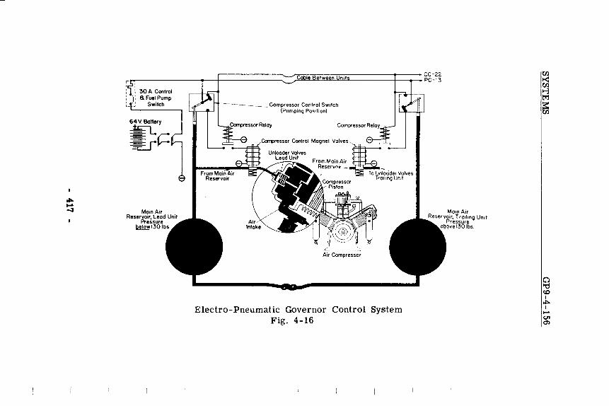
r-------------~_/~~07.~~C7.~--------~------CC-22 r~~------------~~-+--------------~ /~~~~~~L_ ________ ~--~--PC-13
Main Air Reservoir, Lead Unit
Pressure ~1301
11-------___ Compressor Control Switch
'-...... ;orrlpn'ss'o' Relay
(Pumping Posilion)
, Air Compressor
Electro-Pneumatic Governor Control System Fig. 4-16
MalO Air Reservoir. TrOlling Unit
Pressure above 130 Ibs
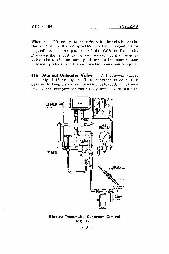
GP9-4-156 SYSTEMS
When the CR relay is energized its interlock breaks the circuit to the compressor control magnet valve regardless of the position of the CCS in that unit. Breaking the circuit to the compressor control magnet valve shuts off the supply of air to the compressor unloader pistons, and the compressor resumes pumping.
414 Manual Unloader Valve A three-way valve, Fig. 4-15 or Fig. 4-17, is provided in case it is
desired to keep an air compressor unloaded, irrespective of the compressor control system. A raised "T"
TO COMPRESS UNLOADER VALVES
MANUALLY UNLOADED
Electro-Pneumatic Governor Control Fig. 4-17
- 418 -
SYSTEMS GP9-4-156
pattern on the face of the valve indicates the flow of air through the valve. The valve is normally positioned so as to direct the air supply to the unloader valves through the compressor governor control. To manually unload the air compressor, turn valve to bypass main reservoir air supply to the unloader valves around the compressor governor control.
415 Draining Of Air System The air system should be drained periodically to prevent moisture from
being carried into the air brake and electrical control air systems. The frequency of draining will depend on local conditions and can be determined by practice. It is recommended that draining be done at the time of each crew change, until a definite schedule can be determined by the individual railroad.
- 419 -


![GENERAL ELECTRIC DIESEL-ELECTRIC LOCOMOTIVE 2500 HORSEPOWER [196306] (RFS, OCRSIE).pdf · 2018-02-07 · Design The General Electric Model U25B diesel-electric locomotive is especially](https://static.documents.pub/doc/80x56/5e7132607c04ab15ef003710/general-electric-diesel-electric-locomotive-2500-horsepower-196306-rfs-ocrsiepdf.jpg)


