Directorate of Manned Spaceflight and Microgravity Direction des Vols Habité et la Microgravité on station in this issue Welcome Onboard! Jörg Feustel-Büechl ESA Director of Manned Spaceflight and Microgravity ESA and the Crew Return Vehicle 6 Eckart D. Graf News 8 Three ESA Astronauts Flying on 10 Two Space Shuttle Missions ESA Success with Foton-12 12 Antonio Verga, Pietro Baglioni & René Demets ESA’s Moscow Office 14 Alain Fournier-Sicre The Erasmus User Centre 16 Jean-Claude Degavre ATV’s Russian Docking Sytem 20 Frank Bouckaert Gravity Triggers Microtubule 24 Pattern Formation In Vitro James Tabony The MOMO Facility 28 Thomas Berrenberg, Thomas Fuhrmeister, Bernd Kauerauf, Stephan Rex & Harmut Helmke The Newsletter of the Directorate of Manned Spaceflight and Microgravity number 1, december 1999 foreword microgravity x-38/crv docking missions focus on recent & relevant Welcome to the first issue of the On Station newsletter of ESA’s Directorate of Manned Spaceflight and Microgravity. On Station combines and replaces the former Microgravity News and Columbus Logbook newsletters. Its name reflects the potential readership: On Station is a metaphor for ‘being ready’ or ‘being on post’.This approach is not limited to the International Space Station, but also covers the on-going microgravity projects, whether they make use of the International Space Station, the US Space Shuttle, Russian Foton capsules, European sounding rockets, parabolic flights or drop towers and tubes. Today, the Directorate of Manned Spaceflight and Microgravity is responsible for the management of several major programmes with more than 20 individual projects, ranging from the Columbus laboratory, through the Automated Transfer Vehicle and the European share in the Crew Return Vehicle, to International Space Station Utilisation, Microgravity Facilities for Columbus and the EMIR programmes. Altogether, they represent an average annual budget of almost EUR500 million, of which 85% is placed as contracts with European industry. Some 3600 highly skilled jobs in Europe are directly related to these programmes and projects. The large majority of our projects were approved at the ESA Council meeting at ministerial level in Toulouse in October 1995 and formally started on 1 January 1996. Since then, 40% of the allocated budget has been spent and many hardware elements are nearing completion – a good reason to keep you informed with more up-to- date information than is possible through the classical channel of the ESA Bulletin. Information tools have profoundly changed over the past few years and, like many others, the Directorate of Manned Spaceflight and Microgravity is making use of the Internet (http://www.estec.esa.int/spaceflight). ESA has also started its own daily television service over a Eutelsat direct TV satellite (for more information see: http://television.esa.int). But even in the era of e-mail and the paperless office, we feel that there is still a need and a real added-value for a paper newsletter. Welcome Onboard! Jörg Feustel-Büechl ESA Director of Manned Spaceflight and Microgravity
Transcript
Directorate of Manned Spaceflight and MicrogravityDirection des Vols Habité et la Microgravité
on stationin this issue
Welcome Onboard!Jörg Feustel-BüechlESA Director of Manned Spaceflightand Microgravity
ESA and the Crew Return Vehicle 6 Eckart D. Graf
News 8
Three ESA Astronauts Flying on 10Two Space Shuttle MissionsESA Success with Foton-12 12Antonio Verga, Pietro Baglioni & René Demets
ESA’s Moscow Office 14Alain Fournier-SicreThe Erasmus User Centre 16Jean-Claude Degavre
ATV’s Russian Docking Sytem 20Frank Bouckaert
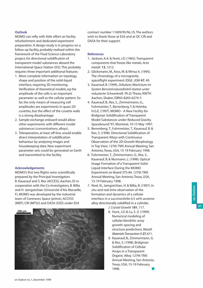
Gravity Triggers Microtubule 24Pattern Formation In VitroJames TabonyThe MOMO Facility 28Thomas Berrenberg, ThomasFuhrmeister, Bernd Kauerauf,Stephan Rex & Harmut Helmke
The Newsletter of the Directorate of Manned Spaceflight and Microgravity
number 1, december 1999
foreword
microgravity
x-38/crv
docking
missions
focus on
recent & relevant
Welcome to the first issue of the On Stationnewsletter of ESA’s Directorate of MannedSpaceflight and Microgravity. On Stationcombines and replaces the formerMicrogravity News and Columbus Logbooknewsletters. Its name reflects the potentialreadership: On Station is a metaphor for‘being ready’ or ‘being on post’. Thisapproach is not limited to the International
Space Station, but also covers the on-going microgravity projects,whether they make use of the International Space Station, the USSpace Shuttle, Russian Foton capsules, European sounding rockets,parabolic flights or drop towers and tubes.
Today, the Directorate of Manned Spaceflight and Microgravity isresponsible for the management of several major programmes withmore than 20 individual projects, ranging from the Columbuslaboratory, through the Automated Transfer Vehicle and theEuropean share in the Crew Return Vehicle, to International SpaceStation Utilisation, Microgravity Facilities for Columbus and the EMIRprogrammes. Altogether, they represent an average annual budgetof almost EUR500 million, of which 85% is placed as contracts withEuropean industry. Some 3600 highly skilled jobs in Europe aredirectly related to these programmes and projects.
The large majority of our projects were approved at the ESACouncil meeting at ministerial level in Toulouse in October 1995 andformally started on 1 January 1996. Since then, 40% of the allocatedbudget has been spent and many hardware elements are nearingcompletion – a good reason to keep you informed with more up-to-date information than is possible through the classical channel ofthe ESA Bulletin.
Information tools have profoundly changed over the past fewyears and, like many others, the Directorate of Manned Spaceflightand Microgravity is making use of the Internet(http://www.estec.esa.int/spaceflight). ESA has also started its owndaily television service over a Eutelsat direct TV satellite (for moreinformation see: http://television.esa.int). But even in the era ofe-mail and the paperless office, we feel that there is still a need and areal added-value for a paper newsletter.
Welcome Onboard!
Jörg Feustel-BüechlESA Director of Manned Spaceflight and Microgravity
INTRO.q 11/8/00 10:46 AM Page 1
With the launch in 1998 of its first twoelements, Zarya and Unity, theInternational Space Station, considered bymany people for a long time as an abstractidea of a remote future, has becomereality. It is even regularly visible to thenaked eye as one of the brightest starsover Europe (for overflight schedules andmaps visit <http://www.estec.esa.int/spaceflight/msmnews.htm> and followthe link to ‘Visibility of the InternationalSpace Station’). Other key elements aresoon to be launched and the Station isexpected to be permanently inhabitedand used for scientific and technologicalexperiments beginning in 2000. Even ifEurope’s own laboratory on the Station,Columbus, is not scheduled for launchbefore 2004, Europe will not be absentfrom the early Station: the next element tolaunch, the ‘Zvezda’ (star) Russian ServiceModule is outfitted with a computersystem made in Europe, the DataManagement System for the RussianService Module (DMS-R), built by aEuropean industrial consortium under ESAcontract. The same module will also carrythe Station’s first externally mountedexperiment, the European GlobalTransmission System (GTS). More reasonsfor us to be ‘on station’!
This newsletter is produced for thespace community at large. We are writingfor readers from industry who are involvedin the development of our manyprogramme elements, as well as thescientists from research institutes who areinterested in the utilisation of theEuropean experiment facilities, rangingfrom the Station to the European AirbusA300 zero-g aircraft. The representativesof partner space agencies andgovernmental delegates from ESAmember states will also find usefulinformation. But On Station will also bevaluable for the media and the generalpublic interested in spaceflight topics.
Where Do We Stand?For this first issue it might be of help,especially for those of you who have notso closely followed our activities in thepast, to summarise where we stand today,4 years after the Ministerial Council ofToulouse, with 5 years ahead of us untilthe completion of the developmentprogramme for the European participationin the International Space Station.
For the Columbus laboratory, the fixed-price industrial contract for developmentand manufacture was placed in March1996. It was ESA’s largest single-evercontract. Since then, Columbus hassuccessfully passed the Preliminary DesignReview (PDR), and the Critical DesignReview (CDR) is approaching. Thestructure for the flight unit is alreadyunder assembly in Turin. The laboratory’sutilisation potential has been significantlyenhanced by the addition of externalpayload facilities.
The European experiment facilities foraccommodation inside Columbus (and, asfar as the Material Science Laboratory isconcerned, in the US Laboratory) arecovered by separate projects. Theycomprise the four elements (Biolab, FluidScience Laboratory, Material ScienceLaboratory, and the European PhysiologyModules) of the Microgravity Facilities forColumbus (MFC), the European DrawerRack and the European Storage Rack. ForBiolab, the Fluid Science Laboratory andthe Material Science Laboratory, the PDRsat system level were successfullycompleted in 1999 and the CDRs areplanned for 2000. For the European
Physiology Modules, the developmentcontract was signed in May 1999. ARequest for Quotation for Phase-C/D ofthe European Drawer Rack was issued toindustry recently. The European StorageRack, the development of which is lesstime-critical, is under definition.
On the Automated Transfer Vehicle(ATV), for which the Phase-C/D contractwas awarded to industry in November1998, there has been major progress in theoperational scenario and the technicaldefinition of the vehicle, despite the highlycomplex nature of its interfaces with theRussian Segment of the Station, for whichan agreement has been reached with ourRussian partners from both industry andthe Russian Space Agency (now calledRossaviakosmos). The ATV’s PDR isscheduled for February/March 2000.
In the field of reentry technologies,with the successful flight of theAtmospheric Reentry Demonstrator onthe third Ariane-5 mission, in October1998, Europe has entered the veryexclusive club of space-faring nations whoare able to conduct a space mission frombeginning to end: launching a payloadinto space and returning it to the ground.Building upon this concrete experience,and the expertise previously acquiredthrough the Hermes programme, Europeis participating in NASA’s X-38 project,which is the prototype and unmanneddemonstrator vehicle for the Crew ReturnVehicle (CRV), the future lifeboat for theStation crew. The X-38 project is welladvanced and the assembly of the V201orbital test vehicle is nearing completion.
At the Ministerial Council Meeting ofBrussels in May 1999, the ESA MemberStates participating in the InternationalSpace Station Programme decided on the
2-
on
Station
on Station no. 1, december 1999
foreword
The Zvezda RussianService Module carriesESA’s DMS-R.
INTRO.q 11/8/00 10:47 AM Page 2
initiation of the Exploitation Programmeand complemented it by a specificprogramme covering the participation ofEurope in the Crew Return Vehicle, thusensuring continuity in European reentrytechnology activities, and at the sametime offering a possibility for theparticipating states to pay their share inthe variable cost of Station operationsthrough an investment in technology. TheCRV is an illuminating example of a newquality and depth of cooperation betweenESA and NASA. At the same time, it is anunprecedented model for a highlyadaptive approach of global cooperationuniting in a strategic alliance the interestsof international and national spaceagencies, industries and even regionalgovernmental entities. In addition to theindustrial teams in 22 companies in eightEuropean countries, a team of Europeanengineers from space agencies andindustry is presently working on the X-38programme, together with their Americancolleagues, in a joint team based at theNASA Johnson Space Centre in Houston.
Using the Space StationThe ultimate goal of Europeanparticipation in the Station is to takeadvantage of the large utilisation potentialit offers. Europe’s preparation for Stationutilisation is well advanced. Severalannouncements of opportunity havealready been issued, inviting scientists,engineers and the application-orienteduser community to submit experimentproposals. These announcements receivedoverwhelming responses, not only fromthe ‘classical’ user community of lifesciences and physical sciences, who areinterested in the Station’s microgravityenvironment, but also from new user
groups in the field of application-orientedexperiments and services. It is worthpointing out that the Station’s firstEuropean utilisation payload will be anapplication-oriented externally mountedexperiment, called GTS (GlobalTransmission System), which will distributesynchronisation signals to radio-controlledwatches. From the Station orbit, thesystem is able to reach 95% of the Earth’spopulation. GTS will also be used to testand demonstrate a new worldwide servicecapable of blocking stolen cars directlyfrom space.
For the preparation of the firstexperiment facilities and the support toexperiments that have been proposed oralready selected for the early utilisationphase, ESA has placed a significantnumber of contracts with Europeanresearch institutes, industry and nationalagencies. Two European symposia onStation utilisation were held in 1996 and1998; the first global utilisationconference, called Forum 2000 and jointlyorganised by all five International Partners(USA, Russia, Europe, Japan and Canada) isplanned for Berlin in summer 2000.
All experiment proposals submitted inresponse to the Announcements ofOpportunity are not only analysed byspecialists from ESA and industry toinvestigate their technical feasibility,compatibility with operational proceduresand compliance with safety rules, but alsoassessed for their scientific relevance andthe soundness of the proposedexperimental approach by Peer Reviews.The Peers are selected according to theirscientific renown and expertise in theproposed research disciplines. The PeerReviews assure that the InternationalSpace Station will become and remain aresearch institute for world-class science.ESA is presently formulating, incooperation with all interested partners inEurope, an overall strategy, as well as theassociated practical administrative andtechnical procedures, for extending theaccess to the Station to commercial users.The issues at stake touch not only financialaspects, but also questions of legalresponsibility, selection criteria and theprotection of intellectual property andconfidential business data.
In order to make potential users awareof the Station’s utilisation possibilities fortheir own business or research, and tohelp interested users in getting access tothe station, ESA has built up theInternational Space Station Erasmus UserCentre at Noordwijk. The centre’s functioncan best be described as a combination ofa marketing centre with a customer care
service. It has the task of providinginformation and practical advice andguidance to Station users and supportingand coordinating the informationactivities of the various national UserSupport and Operations Centres (USOCs)in Europe. It will also contribute toincreasing the awareness of the Stationwith decision makers, media and theEuropean public at large. An importantaspect of the centre’s mandate will be tomake the results of the experimental workperformed onboard the Station betterknown and to bring together scientificteams working in similar fields of research.
According to the agreementsgoverning the cooperation of the fiveInternational Partners, the right to makeuse of the Station’s research potentialbegins only with the arrival of thePartner’s own ‘real estate’ on the Station.The Columbus laboratory formallyconstitutes the European entry ticket tothe Station. It is presently scheduled forlaunch in 2004. In order to give Europeanusers earlier access to the Station, ESA hasnegotiated with NASA and the Russianspace agency Rosaviakosmos thepossibility of using part of their payloadaccommodation capabilities. In this way,European users have access to the US‘Destiny’ laboratory and to externalpayload-carrying structures on the USTruss and the ‘Zvezda’ Russian ServiceModule.
Barter ArrangementsIn exchange for the utilisation rights onthe US elements, ESA is providinglaboratory equipment made in Europe toNASA. ESA has also negotiated forEuropean experiments to fly on NASA’sSTS-107 Space Shuttle mission in early2001, in exchange for a Super Guppyaircraft that had previously been used totransport Airbus elements between thevarious European Airbus manufacturingsites.
Further utilisation rights on the USSpace Shuttle will be obtained inexchange for the delivery by Europe of theCupola. The function of the Cupola for theInternational Space Station can becompared to that of a control tower foraircraft operations around an airport. It is amulti-window dome, sitting on one of theStation’s three connecting nodes, fromwhere the astronauts monitor and controlthe external operations performed bytheir fellow astronauts and the stationrobots, as well as the proximity operationsof arriving or departing space vehicles.
The US Space Shuttle will carryColumbus to the Station. Instead of paying
-3
on
Sta
tio
n
on Station no. 1, december 1999
The International Space Station is the largest internationalcivil engineering project ever undertaken. (ESA/D. Ducros)
INTRO.q 11/8/00 10:47 AM Page 3
cash to NASA for this launch service, ESAwill pay in kind, with products developedand manufactured by European industry:two of the Station’s three connectingnodes, together with other hardware andengineering services, will be provided byESA.
The various barter agreements, as wecall the cooperation scheme whereby ESAdelivers European hardware against theprovision by other Partners of hardware,services or utilisation rights, have resultedin a closer cooperation with all of the fourInternational Partners. They avoidedunnecessary duplication of effort andmade the cooperation more efficient. Atthe same time, they allowed the Station’sutilisation possibilities by European usersto be expanded. They have also resultedin the non-negligible benefit that ESA hasplaced additional development andmanufacture contracts, in highlyinteresting technological areas, worthEUR280 million, with European industry,instead of paying European money tohardware or service providers outside ofthe European economic system.
European AstronautsEven in such a highly-automated androbotic environment like the InternationalSpace Station, where many functions areremotely operated and monitored fromthe ground, astronauts have an importantrole to play. As onboard engineers, theirintelligence, mobility, dexterity andtactility, which are unmatched by anyrobot to date, are an important factor inthe mission success of this firstpermanently occupied international off-shore platform above the Earth’satmosphere. 1999 saw the creation of thesingle European Astronaut Corps, underESA responsibility, based at the EuropeanAstronaut Centre in Cologne, which, froman organisational point of view,constitutes one of the four departmentsof the ESA Directorate of MannedSpaceflight and Microgravity. The transferof national astronauts to the singleEuropean Astronaut Corps, and thedismantling of the national astronautcorps, was not only the visible sign thatEurope wants to speak with one voice inastronaut matters, but also further proofthat the Station is a powerful driver forthe reinforcement of existing, and thecreation of new, international cooperationstructures. At the end of 1999, with 15astronauts in the European AstronautsCorps, and one more expected to join in2000, the build-up of the corps and thetransfer of the national astronauts havebeen almost completed.
In the recent past and the near future,several Europeans have been or will beflying to space. Pedro Duque was a crewmember on STS-95 in October/November1998; Michel Tognini on STS-93/Chandrain July 1999; Jean-Pierre Haigneré workedfor 6 months on the Mir station, fromFebruary to August 1999, thus setting anew world duration record for non-Russian astronauts; Claude Nicollier andJean-François Clervoy are scheduled forlaunch with the third Hubble ServicingMission on STS-103 in December 1999;and Gerhard Thiele will be onboardSTS-99/SRTM in January 2000. If all goesto plan, the first European astronaut to flyto the International Space Station will beUmberto Guidoni, who is scheduled forthe first Space Shuttle mission in thesecond half of 2000.
Microgravity ProgrammesExperimentation in space is not limited tothe International Space Station. Inparticular for physical and life sciencesexperiments in weightlessness, ESA alsomakes use of European sounding rockets,Russian retrievable capsules and the USSpace Shuttle. Space itself is not aprerequisite for microgravity experiments,since parabolic flights or drop towers andtubes provide at least several seconds ofweightlessness conditions of Earth. Thesecarriers and facilities can usefullycomplement or help in preparing andvalidating experiments in space. Theiractivities are covered by the microgravityprogrammes EMIR-1, EMIR-2 and EMIR-2Extension.
Sounding rockets offer shortturnaround times of 1-2 years betweenexperiment approval and flight, sincethere are a large number of reusableexperiment modulesavailable for a broadspectrum ofinvestigations. At theESRANGE soundingrocket launch site inKiruna, Sweden, ESAand the Swedish SpaceCorporation have setup over the past 15years an excellentinfrastructure for thelaunch of three typesof sounding rocketsproviding 3-13 minutesof microgravity, andwith well-equippedlaboratories for
experiment preparation.During the last 2 years, theMaser 8 mission, the Maxus 3mission and two MiniTexusmissions (MT5 and MT6), allof which were 100% fundedby ESA, have flownsuccessfully. The mostrecent mission was Maser-8,launched on 14 May 1999from Kiruna. The payloadwas safely brought back tothe launch site by helicopterabout 1.5 hours after lift-off.Despite significant technicaldifficulties that had to beovercome during thedevelopment of the flight hardware, anddespite a number of problems that had tobe solved during the launch campaign, allfive onboard experiments were executedsuccessfully and interesting scientificresults have been achieved. Also, the newMaser Service Module performedaccording to expectations.
Based on the high scientific return, theuse of sounding rockets has alwaysreceived the unanimous support of theESA Advisory Groups. The EMIR-2Extension Programme will thereforecontinue to cover sounding rocketactivities over the coming years. This,together with Germany’s nationalsounding rocket campaigns, will maintaina viable sounding rocket programme forEurope. The next missions in preparationare Texus-37 and -38 in March 2000,Maxus-4 in April 2001 and Maser-9 inNovember 2001.
On 9 September 1999, the RussianFoton-12 capsule with 11 ESAexperiments onboard was launched fromthe Plesetsk cosmodrome and returned
15 days later to Earth,landing near Orenburg,Russia. The experimenthardware was inexcellent condition.Besides ESA, theGerman space agencyDLR, the French spaceagency CNES and theRussian space agencyRosaviakosmos alsoprovided the mission’sscientific payload.
On Foton-12, ESA’snew FluidPac facilitymade its maiden flight,marking theintroduction of ESAfluid physicsexperiments on Foton.For Biopan it was the
4-
on
Station
foreword
Preparing for the launch ofMiniTexus 6 from Kiruna.
on Station no. 1, december 1999
INTRO.q 11/8/00 10:48 AM Page 4
third operational flight. Out of Foton’s 11ESA-sponsored experiments, only onefluid physics experiment could not beactivated in space because of a hardwaremalfunction. FluidPac with its TeleSupportUnit, Biopan and the autonomousexperiments (Algae, Symbio I and SymbioII, Stone) were all returned, and theevaluation of the experiment data is inprogress. The Agat furnace, provided byDLR and utilised 50% by ESA-selectedexperiments, also performed nominally.Negotiations are underway with ourRussian partners on a further Fotonmission.
Future Flight OpportunitiesEMIR-2 also provides for the use of the USSpace Shuttle for flying ESA experimentfacilities. The next will be the reflight ofthe Morphological Transitions in a ModelSubstance (MOMO) and the flight of theGranada small and passive proteindiffusion and crystallisation package, onSTS-101/Spacehab. This is a logistics flightto the International Space Stationscheduled for 2000, after the launch ofthe Russian Service Module.
The STS-107/Spacehab mission in early2001 will see an important Europeanpayload. In the framework of theESA/NASA arrangement on the delivery ofa Supper Guppy aircraft for the transportof Space Station elements to NASA, ESAwill have the right to fly Biobox-5, theFacility for Adsorption and SurfaceTension (FAST-2), the Advanced ProteinCrystallisation Facility (APCF-6) andBiopack. In addition, ESA has procured ona commercial basis from the Spacehabcompany the necessary additionalresources for flight of the AdvancedRespiratory Monitoring System (ARMS).
Although no further Spacehab flightsafter STS-107 have yet been firmlymanifested by NASA, we expect they willmaterialise. As an alternate option for
microgravity payloads, it canbe assumed there will be flightopportunities on Space ShuttleStation assembly flights.Although their typicaldurations of 8-10 days areshorter than the normal 16-daySpacehab flights, we believethat most of the ESA-sponsored experimentsselected for flight could becarried out using theseassembly flight opportunities.We are therefore exploring thepossibility of flying Biopackexperiments on assemblyflights with the Space Shuttle.
One of the assembly flights is alreadyenvisaged for use by ESA: missionSTS-105/ISS 7A1, scheduled for end-2000.The Advanced Protein CrystallisationFacility (APCF) is scheduled for thismission. It will be accommodated in anExpress rack in the US ‘Destiny’ laboratoryfor 10 weeks and returned to Earth withthe Shuttle flight STS-106/UF-1.
ESA also continues to use the AirbusA300 zero-g aircraft of CNES/Novespacefor experiments under microgravityconditions. The 27th ESA parabolic flightcampaign, the fourth with the A300, tookplace last October in Bordeaux. Elevenexperiments were part of the campaign,four in physical sciences and seven in lifesciences. They involved investigators from18 research institutes from Belgium,Denmark, France, Germany, Italy, Swedenand the USA. It was the first use inmicrogravity of ARMS.
The use of carriers such as soundingrockets, Spacelab (until its last mission,Neurolab, in April 1998), Spacehab, the Mirstation and the Foton capsules over thelast decade has provided the foundationfor a strong intensification of microgravityresearch and applications activities inEurope. This has contributed significantlyto improving basic scientific knowledgeand has led to practical applications thathave helped to improve products andservices with considerable impact.
Last year, the European Academy ofSciences and Art published the reportEuropean Interest in the Scientific Utilisationof Space Station – Fluid Physics, MaterialSciences and Combustion which clearlyidentified the expressed and publishedinterest of scientists for conductingexperiments, among others, incombustion, crystal growth, foamresearch, magnetic fluids, solidification,thermophysical properties and the use ofmagnetic fields in crystal growth.Furthermore, the results of a statistical
analysis show that many hundreds ofEuropean scientists have participated inspace life sciences research. The resultsalso indicate that this researchcommunity is increasingly integrated withground-based biomedical research andthat spaceflight is seen as a real researchtool for addressing not only specificquestions related to microgravity but alsofundamental questions of generalinterest.
A Network of UsersThe ESA Programme for the EuropeanParticipation in the International SpaceStation includes a strong utilisationpromotion element. The strategy is tobring researchers from academia withexperience in microgravityexperimentation into contact withresearchers of industrial research anddevelopment laboratories. The contact isestablished by setting up ‘Topical Teams’addressing topics with high applicationpotential. The first Announcement ofOpportunity in Physical Sciences andMicrogravity Applications had a verypositive response from teams made up bymembers from both industry andacademia. The high interest of industry inmicrogravity applications is reflected bythe significant financial participation ofindustry in the proposed joint projects.
The increasing interest in microgravityexperimentation is the result of a stronginternationally recognised community inscience and industry that has been builtup in the last 15 years. During that period,although there were many individualflight opportunities, only limited numbersof experiments in each topic could becarried out with little continuity orpossibility for extensive iterations. Thissituation will radically change with thestart of International Space Stationutilisation which, thanks to continuousavailability over at least a decade, willallow microgravity research andapplications programmes to be carriedout in a more systematic and iterativemanner.
You can see from this tour d’horizonthat we have interesting times behind usand we are heading for even moreinteresting times!
I am confident, therefore, thatOn Station will become your faithfulcompanion on our journey into thefuture, and I hope that it will be anesteemed in-flight magazine for thewhole International Space Station andMicrogravity communities within andbeyond Europe. ■
-5
on
Sta
tio
n
on Station no. 1, december 1999
ESA is a major partner in the Crew ReturnVehicle and is providing the multi-window cupola. (ESA/Ducros)
INTRO.q 11/8/00 10:48 AM Page 5
The CRV will be used from about mid-2005 as‘ambulance’, ‘lifeboat’ or as alternate returnvehicle for the crew of the International SpaceStation (ISS). ESA’s participation in developingthis next manned spacecraft will be significant,building on the Agency’s responsibility for 15subsystems and major elements of the currentX-38 prototype.
ESA is issuing the Statementof Work for the CRV Phase 1 bythe end of 1999, appropriatelyphased with NASA’s Request forProposals, and is synchronisingthe detailed design activitiesperformed by ESA contractorswith the overall vehicle designactivities performed by USindustry during Phase 1.
ESA and NASA agreed in 1997 that it wouldbe mutually beneficial to extend the X-38partnership to the CRV. These early agreementsat programme management level werefollowed up by a NASA/ESA Protocol onX-38/CRV Cooperation, signed in November1998.
At the May 1999 ESA Ministerial conferencein Brussels, it was decided to link a Europeancontribution to the CRV programme with ESA’sISS exploitation phase commitments. FollowingESA’s detailed programme proposal to theManned Space Programme Board, confirmedand expected contributions by Belgium, FranceGermany, Netherlands, Italy, Spain, Sweden andSwitzerland are substantial.
The scope of the participation will bebeyond the X-38 partnership and will includeadditional major subsystems or elements, likethe novel international berthing/dockingsystem, fin folding and trunnion retraction
6-
on
Station
on Station no. 1, december 1999
X-38/CRV
Eckart D. GrafX-38/CRV Project Manager, D/MSM,ESTEC, Postbus 299, 2200 AG Noordwijk, The NetherlandsEmail: [email protected]
Building upon the highlysuccessful partnership
with NASA for theprototype X-38 spacecraft,
ESA will play a significantrole in the development
and production of theoperational CRV
mechanisms, cold plates, crew seats and thecold gas attitude and orbit control subsystem.
ESA will also be responsible for systemengineering analyses, interface managementfor ESA elements, assemblies or subassembliesand integration or pre-integration of vehicleassemblies.
Early activities of the first phase of the CRVPhase C/D are starting end-1999/early 2000.Phase 1 will be completed shortly after theCritical Design Review, scheduled for August2002. Phase 2 will start in October 2002 andwill cover production of the four vehicles,ending in 2006.
Building on the considerable knowledgeand experience of the X-38 industrial team, ESAwill transition from the present X-38 Phase C/Dinto the CRV Phase C/D, with the programmesoverlapping by about 2 years.
ESA’s major participation in the CRVprogramme will ensure that technologies andsystems expertise needed for future spacetransportation systems will already bevalidated in an operational programme. Theenvisaged CRV production flight test in 2005will precede any European demonstrationprogramme resulting from Future LauncherTechnology Programme (FLTP) studies. Thisflight test would be an autonomous, zero crew,early return of the first CRV flight unit when itis replaced by the second vehicle. ■
CMC Leading Edges
CMC Rudder
FinFoldingMechanism
Fin Structure
Aft Structure
CMC Bodyflaps
Cold Gas System
An article on the X-38and CRV programmes
will appear in theFebruary 2000 issue of
ESA’s Bulletin.
ESA and the ESA and the
CCrreew Rw Retureturn n VVehicleehicle(CR(CR VV ))
-7
on
Sta
tio
n
on Station no. 1, december 1999
X-38: a First for ESAThe development of essential systems and technologies for a reusable reentry vehicle isa first for Europe, and sharing the development of an advanced reentry spacecraft withforeign partners is a first for NASA.
The X-38 programme is using four prototypes: three atmospheric drop-test vehicles(V131, V132 and V133) and a spaceflight test vehicle (V201). V131 has the primary goalof demonstrating the transition from lifting body to parafoil flight. The control surfacesare fixed. It flew successfully on 12 March 1998 and 6 February 1999. V132 isdemonstrating the flight control systems using Electro Mechanical Actuators andadvanced control software technology. It was successfully flight-tested on 5 March 1999and 9 July 1999. V133 will have the ESA-modified shape scaled to a 9.1 m length, withthe primary objective of verifying the aerodynamic shape modifications as well as thecontrol laws. Construction will begin next year.
Following its two flights, V131 has been refurbished to reflect the modified CRVshape, including the berthing/docking mechanism on the top of the fuselage. ThisV131R will resume flight testing early next year.
The space test vehicle,V201, will be deployed from Space Shuttle Columbia in February2002 for a full-up entry test. It is now in assembly at NASA’s Johnson Space Center – theprimary structure is almost complete, the cabin has been successfully pressure-testedand cabin equipment pallets have been installed. During the last 21 months, 22Preliminary Design Reviews and Critical Design Reviews for the ESA contributions havebeen successfully held. The last two CDRs (nose structure and V201 crew seat) werecompleted in July. The rudders were delivered in November, and all other hardware andsoftware elements are in manufacture, to be integrated into V201 during 2000.
Parafoil Guidance Software
InternationalDocking & Berthing System
Display Developments,Human Eng./MMI
Crew Seats
TCS
Thermal Blankets
CMCNose TPS
EquipmentSupportStructure
Landing GearSystem
Cold Plates
Trunnion Retraction Mechanism
Aerodynamic andAerothermodynamic
DatabasesNose
Primary Structure
ESA participation in the CRV programme.
The V201 space-test X-38 prototype is underassembly at NASA’s Johnson Space Center.
ESA made its first rack-level hardwaredelivery to NASA for the InternationalSpace Station in late August when ithanded over the Ground Unit of theMicrogravity Science Glovebox toNASA at the Marshall Space FlightCenter in Huntsville, Alabama. The unitwas complemented in October by theRack Controller (including theApplication Software). The MSGGround Unit will be used to verifyexperiment interfaces and protocolsas well as on-orbit operations.
MSG is a double-rack facility forinitial accommodation in the Station’sUS Lab module. It provides a 255-litresealed environment with a 100 000cleanliness level achieved bycontinuously circulating and filteringthe air inside the glovebox. There aretwo containment levels: one realisedby the sealed work volume, thesecond by maintaining the workvolume’s pressure below ambient. Theglovebox is thus particularly suited forhandling hazardous materials andrepair and maintenance tasks in amanned vehicle. MSG experimentswill be supplied with ISS resources
such as data links, water and aircooling, vacuum/venting, gaseousnitrogen, and 120 Vdc as well asseveral converted power levels.
The delivery of the Training Unitand the Flight Unit are planned forFebruary and August 2000,respectively. Launch is expected onUtilization Flight UF-1 in January2001. MSG’s ownership will betransferred to NASA after theon-orbit commissioning phase.
MSG is an element of ESA’sLaboratory Support Equipmentprogramme, as defined by theESA/NASA Memorandum ofUnderstanding enabling EarlyUtilisation Opportunities on theInternational Space Station ISS. Itsdevelopment andqualification activities arecontracted to anIndustrial Consortiumled by DaimlerChryslerAerospace (D) with theparticipation of BradfordEngineering (NL) andVerhaert (B). ■
ESA’s competition for student spaceexperiments came to a climax inOctober with the awards ceremony inAmsterdam. The teams for all 15 finalproposals were invited to a specialevent during the InternationalAstronautical Federation congress tohear the three winners announced.The team of the best proposal willnow spend time at ESTEC developingtheir experiment for testing on amicrogravity parabolic-aircraft flightcampaign. In time, some of theexperiments may even be adopted tofly on the International Space Station(ISS).
Presenting the awards on 8October 1999 at the Amsterdam RAIconference complex was ESA’sDirector of Manned Spaceflight &
Microgravity, Mr Jörg Feustel-Büechl,supported by Karl Knott (Head ofMicrogravity & Space StationUtilisation Department), Ulf Merbold(Head, ISS Utilisation and MicrogravityPromotion Division) and ESAastronaut André Kuipers.
The Space Station Utilisation ContestCalls for European Students' Initiatives(SUCCESS) competition kicked off inNovember 1998 after ESA decided toinvolve the future generation of spaceusers in the ISS as soon as possible.Almost 1000 universities in MemberStates were notified and a websitewas activated, resulting in more than500 registrations of interest. By thedeadline of 12 March 1999, 126students had provided 103preliminary brief essays. These were
6-
on
Station
on Station no. 1, december 1999
recent & relevant
Recent & Relevant
The MSG Ground Unit at DASA,Bremen (D), ready for shipping
to NASA.
Success for SUCCESS
ESA Delivers Glovebox Ground Unit
evaluated by the independent SpaceStation User Panel (SSUP), a group ofEuropean scientists responsible forselecting the Agency’s ISSexperiments. The SSUP chose 50proposals, involving 65 students. Fromthese, 26 full proposals were receivedby the 27 August deadline forconsideration by ESA’s own expertpanel. Ulf Merbold, ESA’s SUCCESSmanager following the retirement ofAlain Gonfalone, commented,“Wewere very impressed with all theproposals – we even received detailedengineering drawings and fundingprojections.”
ESA then forwarded 15 to the SSUPfor detailed analysis: 8 Technology, 4Physics/Material Science, 2 LifeSciences and 1 Earth Observation.
As in all good competitions, thewinners were announced in reverseorder, with Mr Feustel-Büechl wrilynoting,“The life of an ESA Director isoften a difficult one, but from time to
-7
on
Sta
tio
n
on Station no. 1, december 1999
Recent & Relevant
Orbital Liquid Experiment (OLE)J. Mariano, F. Mancebo, D. Melzoso & P. Vals (Polytechnic University of Madrid)OLE is a compact but versatile fluid physics mini-laboratory housed in theEuropean Drawer Rack to study the gravity-dependence of certain fluidphenomena, particularly fluid drop impacts and thermocapillary non-coalescence. A rotating platform simulates different gravity levels, with a set ofsyringe needles generating droplets of different sizes. The behaviour of dropsimpacting on the flat surface of the same fluid in a container are recorded by aCCD camera. Depending on the conditions, drops can bounce off the surface,coalesce or coalesce briefly before a different drop emerges. In thermocapillarynon-coalescence, spontaneous coalescence between drops of the same liquidcan be permanently inhibited by imposing a temperature difference to drivethermocapillary surface flows. These draw air into the layer between the drops,preventing merger. This is a new and promising field of study; an envisagedapplication is the production of perfectly smooth self-centring and almostfrictionless bearings.
SEE-US (Space Earth Observation Experiment for Universities andSchools)P. Ariaudo, Microgravity Advanced Research & Support Centre, ItalySEE-US uses a simple CCD camera with a 300-500 mm focal length lens andautonomous transmitter to broadcast 30x30 km Earth views from the ISS tolow-cost ground stations in schools and universities. As a secondary payload,it shares volume and power with an existing ESA payload on a nadir-pointingExternal Pallet. The whole of the Earth would be imaged in 2-3 years, relayingone or two images on every pass at 64-256 kbit/s. A 1024x1024-pixel CCDimage requires about 1 Mbyte and up to 1 min to transmit.
ATTISTA: An Attitude Stabilisation Device for Free Floating ToolsA. Glennmar, The Royal Institute of Technology, SwedenA. Roger, University of Glasgow, UKATTISTA is a 3.4 kg clip-on attachment for holding free-floating equipment suchas cameras and lights in a fixed orientation for astronauts working aboard theSpace Station. It uses 4 cm-diameter reaction wheels in a closed control loopand either three rate gyros or a CCD vision system to control and sense bodyrates. The CCD is preferable because the pointing is fixed within the Stationframe of reference, whereas the gyro’s inertial pointing drifts with the Station’sown motion. ATTISTA’s pointing accuracy is at least 1-degree. Depending onthe battery and motors selected, the running time could be about 5 hours.
time there comes a moment ofpleasure – and SUCCESS is one suchmoment!”
The third prize of a trip to see thelaunch of an Ariane (Kourou) or SpaceShuttle (Cape Canaveral) wasawarded to Anna Glenmar andAlexander Roger for their “ATTISTA”proposal of a gyro-stabilised pointingunit for attaching to cameras, torchesand so on to allow astronauts to workhands-free.
The second prize of a laptop waswon by Paolo Ariaudo for his plan tomount an Earth-viewing video
camera on the Space Station truss forbroadcasting to schools and thepublic via the Web.
The winning entry came from the4-man team of Jose Mariano,Fernando Mancebo, Daniel Meizosoand Pablo Vals. Their Orbital LiquidExperiment (OLE) would study thebehaviour of liquid droplets inmicrogravity. As their prize, each teammember will spend 3 months atESTEC preparing their experiment fora flight campaign on the NovespaceA300 Airbus based at Bordeaux. ■
The SUCCESS winners receive their certificates from MrJörg Feustel-Büechl.
ESA astronaut André Kuipers (centre) works with theAdvanced Respiratory Monitoring System (ARMS)
during the 27th ESA parabolic flight campaign of 26-29October aboard Novespace’s Airbus A-300 aircraft in
France. The campaign focused on medical (emphasisingrespiratory physiology) and physical science
experiments. Two employed ARMS, planned to make itsspace debut aboard Space Shuttle STS-107 in 2001.
ARMS produces electrocardiograms and respiratory gasconcentration/flow and blood pressure measurements
of human test subjects.ESA will run two parabolic campaigns annually
over the next 4 years. Scientists are regularly invited tosubmit experiment proposals for review and selection
by peers. ESA is including student experiments toencourage the scientists of tomorrow to learn about
experimentation in weightlessness and the extensiveresearch opportunities offered by the International
Space Station. Further information on ESA parabolicflights can be found at:
http://www.estec.esa.int/spaceflight/parabolic ■
New Head of Programme IntegrationManuel Valls took over as MSM’s Headof the Manned Spaceflight Programme
IntegrationDepartment on 1 September.On Station asked himabout the positionand his experience inthe space field:
“My job has twoequally importantfacets. One isprogramme control,
which takes account of planning andmonitoring of costs, schedules andgeographical returns for all thevarious programmes and projectswithin the Directorate, such asColumbus and ATV. The other is thedevelopment of programme policy,which essentially encompasses thenegotiations of agreements with theother International Partners, such asimplementation of memoranda ofunderstanding and barteragreements, agreements withMember States and inter-directorateagreements.
“For the last 28 years I havedevoted myself to the aerospacesector. First, in aircraft design, then inseveral space programmes, including
Spacelab – so I am an early memberof the community of mannedspaceflight. After a number of yearsinvolved in aeroengines, I came backto pure space activities, to which Ihave devoted my time as a director inmy previous company, SENER.” ■
New Head of ISS Utilisation andMicrogravity PromotionMarc Heppener recentlybecame Head of Divisionfor ISS Utilisation andMicrogravity Promotion. Hetold On Station:
“My job title is quite amouthful but it means thisDivision interfaces with allSpace Station users. So allfirst contacts, be they with scientistsor industries who want to use SpaceStation, and in whatever applicationfield, microgravity research,technology, Earth observation orspace sciences, all initial contacts willbe here, and we see to the evaluationand selection of new projects. Ofcourse, we also actively promote alltypes of utilisation on Space Station.In the microgravity area it is a littlebroader: we also solicit experimentsfor Spacehab flights, sounding rocketsand parabolic flights. When the
8-
on
Station
on Station no. 1, december 1999
recent & relevant
Recent & Relevant
STAFF NEWS projects are selected, they aretransferred to the Divisionsresponsible for the development,integration and operation ofhardware, but we remain in the loopfor the scientific aspects.
“I trained as a chemist and also inbio-chemistry, so I know a little bitabout biology. In addition, my PhDdealt with spectroscopy, which laterhelped me enormously in
understanding problems inEarth observation andastrophysics. I have beenworking at the SpaceResearch Organization ofthe Netherlands (SRON),where I was initiallyresponsible for X-raydetector development forspace science and later then
became responsible for 10 years forthe Dutch scientific programmes inmicrogravity and Earth observation.So I hope that I bring expertise in atleast three different disciplines thatwill make use of Space Station:microgravity, Earth observation andspace science. And I also developedmany contacts with government andindustry. For the last 10 years, I wasDutch delegate to many ESAprogramme boards, and for the last3 years I was chairman of themicrogravity programme board.” ■
Manuel Valls.
Marc Heppener.
New Head of EACErnst Messerschmid will take over asHead of the European AstronautsCentre on 1 January 2000. DrMesserschmid flew as a PayloadSpecialist on the Spacelab-D1 missionin 1985. ■
Jean-Pierre Haigneré became Head of the AstronautsDivision in ESA’s Directorate of Manned Spaceflight andMicrogravity and Deputy to the Head of the EuropeanAstronauts Centre on 1 November 1999. Mr Haigneréreturned safely to Earth on 28 August after his 189-day flight as part of the Soyuz-TM29 expedition to theMir space station. He was the fourth ESA astronaut toboard Mir, although he had already visited Mir in 1993as a CNES astronaut. These missions make him theWestern European space duration record-holder. ■
EXPOSE: the kick-off for Phase-C/D with theprime contractor Kayser-Threde (D) for thespace exposure facility for exobiology tookplace on 4 October 1999. The EngineeringModel and hardware for the scientific groundpreparation programme will be ready in mid-2001; the Flight Model is expected to beavailable in early 2002.
TEXUS: the next sounding rocket flights, theTEXUS 37/38 double campaign fromESRANGE, are planned for March 2000.
APCF: the two Advanced Protein CrystallisationFacility flight units are being refurbished atDornier (D) for new missions on Space ShuttleSTS-107 in January 2001 (see below) andaboard the International Space Station in late2000.
STS-107: ESA’s payloads for the 2001Shuttle/Spacehab mission are expected to beBiobox-5, FAST-2, APCF (see above), Biopackand ARMS.
Biolab: the system CDR is expected in early2000 for the Columbus facility that willsupport biological experiments onmicroorganisms, animal cells, tissue cultures,small plants and small invertebrates.
FSL: the subsystem CDRs for the Fluid ScienceLaboratory are planned for early 2000, withthe system CDR by mid-2000.
EPM: the end of Phase-B for the EuropeanPhysiology Modules is expected in early 2000,with the goal of beginning Phase-C/D by mid-2000. The Phase-B mid-term presentation withprime contractor OHB (D) was successfullyheld in October 1999.
PCDF: delivery of the Protein CrystallisationFacility flight unit by prime contractor Dornieris planned for May 2002. Phase-C/D began 22June 1999. PCDF will be accommodated in aEuropean Drawer Rack aboard Columbus.
PEMS: the Critical Design Review of thePercutaneous Electrical Muscle Stimulator isexpected in January 2000. PEMS is beingsupplied by ESA as part of NASA’s HumanResearch Facility on the US Lab; it stimulatesspecific human muscle groups to studymuscle atrophy in weightlessness. Launch willbe about March 2002.
Russian Confinement Study: ESA isparticipating in the study at the MoscowInstitute of Biomedical Problems of four testsubjects confined in the Mir Simulator for 240days (until 20 February 2000) and four in theMars Spaceship Simulator (110 days,concluded in November 1999).
EMCS: Phase-C/D for the European ModularCultivation System began formally at primecontractor Dornier at the end of November1999. EMCS will fly aboard the US Laboratoryof the Space Station.
NEW PUBLICATIONS: two new volumes haverecently been issued. The 188pp Exobiology inthe Solar System and The Search for Life on Mars(SP-1231) is available at a cost of 70 DutchGuilders or EUR32 from ESA PublicationsDivision, ESTEC, Postbus 299, 2200 AGNoordwijk, The Netherlands (fax: +31 71 565-5433). The 41pp Columbus: Europe’s Laboratoryon the International Space Station (BR-144)costs 20 Dutch Guilders or EUR9. It can also beviewed at<http://esapub.esrin.esa.it/br/br.htm>. ■
-9
on
Sta
tio
n
on Station no. 1, december 1999
Recent & RelevantSNIPPETS
ERA Testing at ESTECThe Engineering/Qualification Model(EQM) of the European Robotic Arm(ERA) underwent a week of thermalbalance tests during November 1999in the Large Space Simulator atESTEC. Assembly of the Flight Modelat Fokker Space <http://www.
fokkerspace.nl/products/era/era.htm> isexpected to be completed in May2000, with delivery to Moscowtargeted for end-2000. Launch isplanned for November 2001 aboardthe Space Shuttle as part of Russia’sScience & Power Platform cargo. ■
For only the second time, two ESAastronauts will fly together on theSpace Shuttle, aboard the STS-103servicing mission to the Hubble SpaceTelescope. With launch planned for December as On Station went to press,Claude Nicollier and Jean-FrançoisClervoy are part of the 7-man crewthat will visit Hubble earlier thanpreviously planned because ofproblems with the telescope’spointing gyroscopes.
The Third Servicing Mission (SM3) wasoriginally scheduled for June 2000,with Nicollier participating, but itbecame clear in March that Hubble’spointing system might not survivethat long. Science operations requireat least three gyros but redundancywas lost when the third of the six failedearly this year. SM3 was thus dividedinto two flights, so that SM3A canreplace all six gyros, a guidance sensorand the main computer.The astronautswill also fit Hubble with a newtransmitter and solid-state recorder,and add new thermal blankets.
SM3B will complete the remainingupgrades in late 2000, including thereplacement of ESA’s pioneering FaintObject Camera with a new AdvancedCamera. The FOC will be returned toEarth but its eventual resting placehas yet to be decided. ESAcontributed a 15% share to Hubble’s
development and Europeanastronomers receive in return aguaranteed 15% share of observingtime, although it averages 20% inpractice.
Nicollier, an ESA astronaut since 1978and making his fourth flight, is part ofthe team that will perform at least
four EVAs. An astronomer byeducation, he took part in the firstHubble servicing mission (STS-61) in1993, controlling the Shuttle’s roboticarm while astronauts on the workend performed the delicate repairs tothe telescope. He also served on STS-46 in 1992, using the arm to deployESA’s Eureca retrievable spacecraftfrom the Shuttle, and on STS-75 withthe Italian Tethered Satellite Systemin 1996. Nicollier is currently the chiefof the robotics branch in NASA’sastronaut office and ESA’s leadastronaut in Houston.
Clervoy, a member of ESA’s astronautcorps since 1992 and making his thirdflight, is the lead operator of therobotic arm for this mission. Hepreviously served on STS-66 in 1994using the arm to deploy and laterretrieve the German SPASatmospheric research satellite, and onSTS-84 in 1997, a Shuttle mission tothe Russian Mir space station.
missions
10-
on
Station
on Station no. 1, december 1999
Three ESA Astronauts Flying on This is the secondHubble servicing
mission for ClaudeNicollier. (NASA)
Picture below:Jean-Francois Clervoyis the robot arm (topright) lead operatorfor the latest Hubbleservicing mission.(NASA)
Details of ESA’s astronauts and their activities can be found at<http://www.estec.esa.nl/spaceflight/astronaut/>. The high orbital inclinationof STS-99 (57˚) means that it is visible from most of Europe, while the lower-inclination STS-103 (28.5˚) limits its visibility to southern Europe. Check the siteat <http://spaceflight.nasa.gov/realdata/sightings/index.html> for sightingfrom your own location.
Space Shuttle missions involving ESA astronauts are covered in detail at<http://www.ksc.nasa.gov/shuttle/missions/missions.html>.Photographs can be found at <http://www.ksc.nasa.gov/shuttle/photos/>.For STS-99, <http://www.jpl.nasa.gov/srtm/>, <http://www.dlr.de> and <http://www.asi.it> provide further information.
STS-103 Hubble Servicing MissionNicollier &
Clervoy:
ASTRO. MISSIONS-2.q 11/7/00 11:06 AM Page 2
As this issue of On Station went topress, ESA astronaut Gerhard Thielewas expecting to be launched on hisfirst space mission in January, aboardSpace Shuttle STS-99. The goal of this11-day Shuttle Radar TopographyMission (SRTM) is to generate 30 m-resolution digital topographic andradar maps of 80% of the Earth’s landsurface.
The SRTM radars have already flownaboard the Space Shuttle: the 5.3 GHzUS Shuttle Imaging Radar-C in April1994 and the 9.6 GHz German/ ItalianX-band Synthetic Aperture Radar inOctober 1994. SRTM’s majorinnovation is to fly additional
antennas on a 60 m-long mast – thelongest rigid structure ever used inspace. Simultaneous reception withantennas in the Shuttle cargo bayoffers slightly different views of thesame locations. Combining themgenerates 3D topographic maps anddramatic visualisations of theEarth’s surface. Processing the 9.8Tbytes of raw data – theequivalent of 15 000 CDs – willtake 18 months.
Thiele and his five internationalcolleagues will spend much oftheir time monitoring the radarsand keeping a close check on therecorders. As well as tweaking theShuttle’s position to make surethe radar systems remainperfectly aligned, the crew alsohas the tricky task of deployingthe 60 m mast within 12 h ofreaching orbit. Thiele is teamedwith mission commander KevinKregel and mission specialistJanet Kavandi on one of the two12 h work shifts. Thiele andKavandi are the two crewmembers trained for emergencyspacewalks, so preparing for
contingencies were key elements oftheir training, especially as any one ofa number of scenarios could involve atricky manoeuvre to extend the mastmanually.
"If the latches fail to openautomatically on command then itshould be possible for us to releasethem manually during a spacewalk,"said Thiele. "Even if all goes to plan,the crew will still be very busy. Thismission will create a huge amount of
digital data at a staggering 270 Mbitevery second and it all has to bestored on special tapes using high-rate recorders. Three will be running atany one time and one of our tasks isto ensure there are no problems."Fresh tapes have to be mounted andif any data recorder suffers a problem,there are three backups.
At mission’s end, the mast will befolded and stowed but, should itprove stubborn, a small explosivecharge can separate it from theShuttle.
Thiele has been a member of ESA’sastronaut corps since August 1998.Born in 1953 in Heidenheim-Brenz,Germany, he always wanted to be anastronaut. After completing hisdoctorate in physics at HeidelbergUniversity in 1985, he spent 2 years atPrinceton University researching intolarge-scale ocean circulation. In 1988,Thiele began basic astronaut trainingat the German Aerospace ResearchEstablishment (DLR) and then servedas Alternate Payload Specialist for theSpacelab-D2 mission in 1993. He wasselected by DARA (German Space
Agency) and DLR (GermanAerospace ResearchEstablishment) to attend NASA’sAstronaut Candidate Training inJuly 1996, and qualified 2 yearslater for flight assignment as aMission Specialist.
"It is important to understand asmuch as possible about ourenvironment and this is what Ithink exploration is all about. Weare what we are because wehave never accepted ourboundaries," says Thiele. "For me,going into space is also a verypersonal challenge. It was just adream in the early 1960s butdreams can often come true andI am very fortunate to get thisopportunity." ■
-11
on
Sta
tio
n
on Station no. 1, december 1999
Two Space Shuttle Missions
Gerhard Thiele:STS-99 Radar Mapping Mission
Gerhard Thiele prepares for underwater EVAtraining at NASA Johnson Space Center. (NASA)
ASTRO. MISSIONS-2.q 11/7/00 11:06 AM Page 3
The international Foton-12 mission waslaunched from the Plesetsk Cosmodrome on 9September 1999 carrying a large ESA payload.After 14.6 days in orbit, its descent capsulelanded safely in SW Russia close to the Kazakhborder; the ESA payload was retrieved within
hours and carried back toEurope.
Russia’s recoverable Fotonfree-flyers have been used byESA’s Microgravity Programmefive times since 1991, butFoton-12 marked a new
milestone in terms of payload mass, complexityand scientific diversity. The Agency’scontribution amounted to an unprecedented240 kg – almost half of the total load thatFoton is designed to carry. Included was a newfacility (FluidPac) with its associatedTelesupport unit, which, for the first time,
provided scientists with online monitoring oftheir experiments. Foton’s 11 ESA experimentscovered fluid physics, biology, radiationdosimetry, material science and meteoritics –another first.
The FluidPac/Telesupport combinationenabled the scientists to perform interactiveexperiments from the ground station atESRANGE, Kiruna (S) or their home laboratories.Two fluid physics experiments (MAGIA andTRAMP) were successfully performed, whileBAMBI suffered a technical failure and had tobe aborted.
FluidPac is the first automatic fluid physicsinstrument flown on Foton. Its multi-diagnostics include two Electronic SpecklePattern Interferometers, a Wollastoninterferometer, three CCD cameras for visualobservation and velocimetry, an IR camera anda variety of temperature, pressure andmicrogravity sensors. Three complexindependent experiment containers, sharing acentral cooling loop for thermal regulation,were accommodated on a rotating carrouseland positioned under the selected diagnosticduring experiment execution. Images and datawere processed and stored on a digital taperecorder, as well as being sent to the groundalong with housekeeping data via Telesupport.In parallel, Telesupport relayed uplinkedcommands to FluidPac.
ESA’s Biopan exposure facility, completing itsfourth flight, performed as hoped. The unit’s
12-
on
Station
on Station no. 1, december 1999
missions
ESAESA SSuccuccess with ess with FFotot on-12on-12Antonio Verga, Pietro Baglioni & René DemetsMicrogravity and Space Station Utilisation Department, D/MSM, ESTEC,Postbus 299, 2200 AG Noordwijk, The Netherlands
ESA’s latest mission wasflown and completed
successfully in September.Here are the preliminary
motor-driven hinge allows its lidto be opened and closed underground command to expose itsexperiments directly to the spaceenvironment, and a variety of
sensors (radiometer, UV, pressure andtemperature) monitor the conditions duringflight. The lid was opened on 10 September,20 hours after launch by telecommand fromthe Moscow control centre and closed after303 hours’ exposure. The data analysed afterflight indicate that the experiments’temperature-control (always difficultfor experiments exposed directly tospace) worked better than ever.
Biopan’s own ablative heatshieldsuccessfully protected it duringreentry, emerging with remarkablylittle damage. The unit was returnedto ESTEC and the experimentsextracted during 28 September.
Like Biopan’s four experiments(Table 1), the standalone ALGAE andSYMBIO went as planned and weresafely recovered after landing. Thenovel reentry study, STONE, withsimulated-meteorite rock samplesembedded in the capsule’s heatshield,went well, although one of the threesamples was lost during descent.
Another ESA experiment processedthree samples in the Agat furnace toinvestigate the diffusion coefficientsof tellurium (Te) and indium (In) ingallium antimonide (GaSb). Otherpayloads, from France, Germany andRussia, also flew on the mission.
Throughout the mission, Foton-12’s
status could be closely followed on theWeb, where a special homepage wasupdated daily. Further information can stillbe found at:
http://www.estec.esa.nl/spaceflight/foton/From a technical point of view, the
mission was undoubtedly a success. Thescientific outcome of ESA’s experimentslooks promising, but it is still too early toprovide a definitive view. We plan to beback in the next issue of On Station withmore comprehensive information! ■
Fig. 3. Foton-12 duringintegration with its Soyuz-Ulauncher at Plesetsk. Thewhite Biopan can be seen attop right.
-13
on
Sta
tio
n
on Station no. 1, december 1999
Table 1. ESA Experiments on Foton-12
Experiment Principal investigator Science field Multi-user facility
MAGIA Prof. D. Schwabe (D) Fluid physics FluidPac/Telesupport
BAMBI Prof. J-C. Legros (B) Fluid physics FluidPac/Telesupport
TRAMP Prof. F.S. Gaeta (I) Fluid physics FluidPac/Telesupport
VITAMIN Dr. N. Dousset (F) Radiation biology Biopan
YEAST Prof. J. Kiefer (D) Radiation biology Biopan
DOSIMAP Dr. G. Reitz (D) Radiation dosimetry Biopan
SURVIVAL Dr. G. Horneck (D) Exobiology Biopan
SYMBIO Dr. G. Briarty (UK) Botany –
ALGAE Prof. H. van den Ende (NL) Cell biology –
STONE Dr. A. Brack (F) Meteoritics –
Te, In in Dr. J.P. Praizey (F) Material science Agat
GaSb
Fig. 1. The FluidPacand Telesupport unit.
Fig. 4. The 2.2 m- diameterFoton-12 reentry capsule withBiopan, soon after landing.
What Do We Do?From the very beginning of ESA’s activities inRussia, everything possible has been done toestablish friendly long-term relations with whatis now known as the Russian Aviation & SpaceAgency (RASA) and Russian partnerorganisations, and to obtain all possiblesupport from the Russian authorities. Two high-level agreements have been signed betweenESA and Russia. That of 1995 granteddiplomatic status to the Mission, while 1997’sgave ESA the right of tax-free importation ofequipment and materials into Russia.
As a small and highly mobileteam of dedicated people, wefeel privileged to be a focus pointof cooperation between Russianand European space industriesand government bodies. ESA’sMoscow Office now totals nineemployees: one Frenchman, oneAustrian and seven Russians. Ourday-to-day work includes
following-up and supporting ESA projects inRussia, developing advanced programmes withRussian participation, issuing a weekly bulletinNews from Moscow (for ESA staff, found via theESTEC TIDC website) covering political,technical and space news in Russia, andlogistical support of ESA delegations to Russia.
The office also provides assistance for thecustoms clearance of equipment and materialsimported via Moscow for the needs of variousprojects. We also organise various publicrelations events aimed at promoting ESA-Russia cooperation. We are involved in a broadrange of activities stretching out from Moscowto TsUP Mission Control Centre in Korolyov, thePlesetsk and Baikonur launch sites, the cities ofNovosibirsk and Krasnoyarsk in Siberia andother places all over Russia.
We cooperate closely with ESA’s Departmentof Manned Spaceflight & Microgravity(D/MSM), supporting Permanent Staff located
in our office, astronauts under training and, ofcourse, all those actually involved in ourcontracts with Russia.
Of course, the International Space Stationnow occupies much of our time. In cooperationwith Russia, ESA is supplying the EuropeanRobotic Arm (ERA) and the Data ManagementSystem (DMS-R) for the Zvezda module.Zvezda, due for launch in November fromBaikonur, also carries the European Global TimeSystem (GTS), and the Matroshka biomedicalexperiment will be added later.
ESA’s Automated Transfer Vehicle (ATV) willuse Zvezda for docking with the ISS, so therehave been large-scale preparatory activitiesunderway for many months. In September, atRSC Energia in the city of Korolyov north ofMoscow, the first ATV Management Meetingtook place in the framework of the ATVIntegration Contract recently established withRSC Energia/RASA. The ESA team was led byJochen Graf and Patrice Amadieu, and itsRussian counterpart by Valeri Ryumin, Energia’s
14-
on
Station
on Station no. 1, december 1999
focus on
FFoocus on ESAcus on ESA’’s Ms Moscoscoow Ow Officfficee
ESA’s Permanent Mission inthe Russian Federation hasbeen stationed in Moscow
since 1993 as the outpost ofESA projects in cooperation
with Russia. Here,On Station takes a look at
its activities.
veteran cosmonaut, and Mikhail Sinelschikov ofRASA.
Space Station ESA/RASA meetings regularlytake place at different levels: I. Directors;II. Department Heads; III. Project Managers. Forexample, September’s ATV meeting was atLevel II, under Mr. Sinelschikov and FrankLonghurst, Head of ESA’s Manned SpaceflightProgramme Department.
Supporting Launch ActivitiesRussia has a long history of space launchesand, despite its current economic, financial andpolitical difficulties, its launchers and launchservices continue to demonstrate a strongexport capability. Several contracts have been
signed to launch ESA payloads on Russianlaunchers from Plesetsk and Baikonur. ESAmicrogravity payloads have flown on the Fotonand Bion spacecraft since 1992, and Foton-12in September made a successful flight carrying240 kg of ESA-sponsored hardware A jointESA/industry team spent more than 2 weeksworking hard at the Plesetsk cosmodrome innorthern Russia getting the experiments ready.ESA’s Moscow Office, ofcourse, supported the teamin its activities in Russia,including logistics,interpretation and– perhaps the most
important – helping tocreate understanding withthe team’s Russiancounterparts and makingthings happen in a mostefficient and European-likeway.
There will be morelaunches of ESA payloadson Russian launchers: twoCluster flights on Soyuz insummer 2000, Integral onProton in 2001 and MarsExpress on Soyuz in 2003. We hope there willbe a Foton-13 in 2 years.
Elsewhere, the Moscow Office facilitatescooperation with Russia on technology andexpertise of space interest for Europeanindustry. For example, reentry technologies andthermal protection has been a traditionallystrong area of research in Russia. ESA is nowengaged in the Inflatable ReentryDemonstration Technology (IRDT) Projectfinanced via the International Scientific &Technical Center (ISTC), together with thespecialists of NPO Lavochkin. ■
Alain Fournier-Sicre heads theMoscow Office
ESA’s Moscow Officesupported the Foton-12 teamin Russia. Biopan is seen herebeing installed on the returncapsule.
-15
on
Sta
tio
n
on Station no. 1, december 1999
This ambitious centre requires an emblem easilyrecognised by potential European scientific users, ISSPartners and the general public. This new motif,designed by Maxime Lavie, highlights the name usingthe official font for ESA’s programmes. Its creatorwanted to ‘…symbolise the strong link the Centre willmaintain between astronaut-scientists and theon-ground European research teams.’ He adds,‘…drawing two figures that represent all men andwomen, of any culture or country, was the mostdifficult task. I took inspiration from cave paintings,the most universal graphical representation ofMankind.’
16-
on
Station
on Station no. 1, december 1999
focus on
Jean-Claude DegavreEUC Project Manager, Electrical Engineering Department, Directorate of Technical and Operational Support,ESTEC, Postbus 299, 2200 AG Noordwijk, The NetherlandsEmail: [email protected]
ISS Robotics Stage
TT he Ehe E rrasmus Uasmus U ser Cser C entrentr eePreparing for a New Era in Space Exploitation
developing major hardwareelements for the Station, ESA hasthe important task of promotingthe Station’s utilisation byEuropean science and technology researchcommunities, and of encouraging newapplications. It must also bring the Station intothe public eye and create a focal point inEurope for the media and opinion leaders.
Serving Candidate UsersExperimenters, payload developers and theirsupport organisations need access to an officialand centrally controlled source of informationon the Space Station. In view of the ISS elementdevelopment responsibility entrusted to ESAand the established formal links between ESAand NASA, the Erasmus User Centre is bestplaced to take over this task. The Centre is thedepot legal for any new information andupdates. The information encompasses theentire library of user accommodationdocumentation jointly established among the
E
RA
SM U S
USER
CE
NT
RE
IN
TERNATIO
NAL
SPACE STATIO
NIntroductionOn 28 June 1999, Monique de Vries, StateSecretary for Transport, Public Works and WaterManagement of the Netherlands, and AntonioRodotà, Director General of ESA, inauguratedthe Erasmus User Centre (EUC) at ESTEC,Noordwijk. The Centre is already promoting
utilisation of the InternationalSpace Station (ISS) by Europeanscience and technology researchcommunities, and encouragingnew applications.
Why do we Need Erasmus?The USA, Europe, Japan, Russiaand Canada began assemblingthe ISS at the end of 1998 andexperiments aboard the Stationwill begin in 2000. In addition to
The Erasmus User Centrebegan operations at ESTEC
this summer to promote theInternational Space
Station’s utilisation byresearch communities and
to encourage newapplications. The ProjectManager describes whatthe Centre offers, and the
plans for the future
-17
on
Sta
tio
n
on Station no. 1, december 1999
INTERNATIONAL SPACE STATION
Erasmus User Centre
Corner to Axis= 166.25 m
Axis A =middle of the doorvertical - 30deg
Axis B=middle of windowvertical + 60deg
Ł
100 cm
Columbus mock-up
Visitors Platform
AccessMobile Platform
Larg
eur=
305
.50
m
The EUC High Bay floor features the futuristic design createdby the French designer Maxime Lavie. He explains that he‘...tried to emphasise the importance of the Columbusmodule, installing it in the Centre of a star-shapedgeometrical pattern of coloured stripes’. This pattern,covering 800 m2, is a symbolic evocation of Europe’s goals inits ISS participation. ‘It can be seen as a giant shining star, ahigh-tech spacecraft landing pad, as well as a target foron-orbit rendezvous manoeuvres.’
EUC FacilitiesHigh Bay • 900 m2
• Cleanroom class 100 000• Mock-up of Columbus module; 1/10th-scale
Station model• ESA-developed multi-user and microgravity
facilities (mock-ups, engineering models)• Standard Payload Outfitting Equipment
(engineering models)• Columbus Laboratory Support Equipment
(engineering models)• ISS Robotics Workshop• Simulation Workshop• Visitors gallery
Multimedia Library• 120 m2
• Visualisation of on-line or recorded SpaceStation data and video; International SpaceStation voice loops; access to Internet, Intranetsites and Data Bases; ISDN interfaces
• Multi-purpose video wall screen (2.2x3 m)• Exhibits, tutorials
Virtual Reality Theatre• Immerse stereo wall or 3-D effect (10-25
visitors sitting)• Single 2.5x3 m screen• Sound and voice facilities
TV Broadcasting Studio• Studio floor (12x12x8.5 m high), with lights• Non-linear video editing and play-out • Extendable video mixer (16 inputs)• Chromakey Blue Limbo (6x8x5 m)• Video interface to graphics station (virtual
Space Station Partners. It comprises technical data describing what the usercan expect from the Station and whatthe Station expects from the user. Itincludes links to the Announcementsof Opportunity Web sites and to other
utilisation-related programmatics. Theinformation constitutes a ‘utilisation database’accessible as much as possible electronically,on the World Wide Web, via the Centre’sintranet and via national supportOrganisations.
The goal is to help candidate users to submitacceptable and innovative experimentproposals.
Familiarising Selected UsersThe EUC High Bay houses replicas of all theaccommodation hardware available toEuropean users for ISS experiments. Themasterpiece is a full-scale mock-up of ESA’sColumbus module, including models of itspressurised multiuser facilities and its ExternalPayload Facility for external exposure facilities.
The models show how an experiment canbe accommodated mechanically and, later,electrically, and what resources can beprovided.
One rack position in the Columbus mock-upincludes the Utility Interface Panel (UIP), whichprovides power, water cooling, data buses,video, nitrogen and vacuum/venting forexperiments.
Mechanically high-fidelity models of anInternational Standard Payload Rack (ISPR, withits transportation frame rack), the EuropeanDrawer Rack (EDR, with mid-deck locker andstandard drawer rack accommodation) and theEuropean Stowage Rack (ESR) are displayed todemonstrate the logistics and stowage factorsaffecting the experimenters.
Columbus is the centrepieceof the High Bay.
For external payloads, models ofthe Express Pallet Adaptor (ExPA),European Technology ExposureFacility (EuTEF) and Coarse PointingDevice (CPD) are also displayed in theHigh Bay.
The goal is to show candidateusers what global accommodationpossibilities are offered by the SpaceStation and, particularly, by theEuropean elements, and to explainwhat resources are available takinginto account the allocations betweenPartners, logistics constraints andhuman factors such as man-machineinterface and safety constraints.
Serving the PublicThe Centre is linked to the US andRussian launch sites and to the UserSupport and Operation Centres (USOC), so thatlive video and voice communications – evenwith the astronauts aboard the Station – canbe organised.
Live and recorded television programmescan be broadcast by the Centre’s TV Studio viarelay satellites, leased line, ISDN and Internet.The Studio supports interviews and pressconferences with call-in from remote sites,including the Station itself. ESA also uses thefacilities to edit and play-out ESA videoproducts.
The Press have access to ESA technicalexperts and managers to organise interviewsand thematic events in the Studio. The Centrelibrary will have a Press section with access toPR materials.
The goal is to attract public attention duringthe space missions of the Station’s 5-year
assembly, and to maintain a repeated andfamiliar ESA image to the public during theexploitation phase.
Visiting the Erasmus User CentreThe Centre is designed to receive groups ofabout 25 visitors without disturbing on-goingactivities. Visitors are welcomed in a pre-showarea that introduces the Station and itsutilisation. Then, they are taken to a 1/10th-scale model of the Station where the assemblysequence can be explained. On their way, theycan watch activities in the High Bay andcontemplate the Columbus module. Then, theVirtual Reality Theatre allows them to ‘visit’ theStation. On their way, they can see themultimedia library and its video wall withmultiple displays of documentation andoperational data from space.
18-
on
Station
on Station no. 1, december 1999
focus on
The Centre’s TV Studiofacilities will be increasinglyused as the Space Station is
assembled. Here, the launchof Zarya is being covered.
The FutureBuilding up a Utilisation DatabaseBuilding up the utilisation database has startedwith the creation of the Microgravity Database,covering the data acquired so far fromspaceflights. An inventory of all the utilisation-related data and documentation on the futureSpace Station is being performed by Vitrociset(I). It will be followed by the creation of thedatabase itself and of the navigation tools tomake it user-friendly.
As an extension to this database and as acomplement to the hardware already availablein the Centre, the development of ‘digitalmodels’ of payload subsystems is envisaged,easily portable on users’ own computers tocomplete their familiarisation and to preparetheir experiment accomodation by virtualreality techniques.
Demonstrating Standard Payload OutfittingEquipmentIn the framework of the Utilisation PreparatoryProgramme, ESA is qualifying Standard PayloadOutfitting Equipment (SPOE). It includes awater/air heat exchanger, a Remote PowerDistribution Assembly and a Standard PayloadComputer (SPLC).
Each SPOE item is represented in the HighBay in its working environment with sufficientfidelity for users to appreciate its advantages.
Installation of Test and Operation FacilitiesThe selected users of a given payload facilitywill be assisted in the planning, development,
integration and operation of theirexperiments by a dedicated FacilityResponsible Centre (FRC). The ErasmusUser Centre is responsible for theEuropean Drawer Rack insideColumbus and will host the dedicateduser support facilities. The Centre willbecome a User Support andOperation Centre (USOC) and will beintegrated in the decentralisedpayload operation scheme baselinedfor exploitating the Station in Europe.
The responsibilities of the EDR FRClocated in Noordwijk are underdefinition but will include:• planning and integration of the EDR
operations;• acceptance of the drawers in the
EDR flight model;• validation of the experiment
operation procedures;• monitoring of the rack’s in-flight
performance in comparison with its groundengineering model.
The EDR is a multi-disciplinary payloadfacility. It will be supported by ExperimentSupport Centres (ESCs), specialising inparticular applications and which could takeover specific science operations, such asperforming telescience ■
Behind the Columbus modulein the High Bay are thecentre’s other facilities, suchas the Multimedia Library, TVStudio and Virtual RealityTheatre. In the foreground isthe robotics area.
-19
on
Sta
tio
n
on Station no. 1, december 1999
Mrs de Vries, State Secretaryfor Transport, Public Worksand Water Management ofthe Netherlands (centre),greets four ESA astronautsfollowing the Columbusunveiling, assisted by AntonioRodotà, ESA Director General(right). From left: UlfMerbold, Andre Kuipers, PedroDuque and Wubbo Ockels.
Visit the Erasmus User Centre web site at:http://www.estec.esa.int/spaceflight/usercentre
IntroductionIn order to avoid the cost of developing aEuropean docking system and to becompatible with the Russian Segment of theInternational Space Station (ISS), ESA’sAutomated Transfer Vehicle (ATV) is adopting aslightly modified Russian Docking System(RDS) of the type used on Soyuz-TM andProgress-M vehicles. The barter agreement wassigned in March 1996, under which ESA hasprovided the Data Management System(DMS-R) for Russia’s Zvezda service module andthe Agency will receive two flight sets of thedocking system’s active portion.
ObjectiveThe goal is to allow a harmless contactbetween the 20 t ATV and the 450 t ISS,dampen their relative motions, align them, andcreate a rigid mechanical connection capableof transmitting the ATV’s reboost and attitudecontrol thrust loads to the Station. Theconnection is pressurised for access to the ATVPressurised Module to unload the pressurisedcargo, water and gasses. After loading the ATVwith Station waste, the RDS allows undockingbefore destructive reentry into the atmosphere.
DescriptionThe RDS consists of the ATV’s ‘active’ part andthe ‘passive’ section installed on the Zvezdaservice module.
The Active Docking Assembly (ADA) consistsof a housing with hooks and connectors, the80 cm-diameter hatch, an alignmentmechanism with three levers and their rollers,an extendible boom, and a probe head withfour latches (Figs. 1-3).
The Passive Docking Assembly (PDA)consists of a housing with hooks andconnectors, and the hatch with probe headlatch receptacle (Fig. 4).
OperationShortly after ATV launch, the ADA boom isextended from its launch position to itsdocking position, which also extends the threeinterconnected levers and their rollers. TheLatch arm keeps the probe head latchesextended.
When the probe head contacts the innersurface of the PDA’s cone, the head’s fourlinked petals are compressed (Fig. 5). Below thepetals, contact switches transmit the ‘contact’signal to the ATV (Fig. 6), which accordingly
20-
on
Station
on Station no. 1, december 1999
docking
Connecting with the
IntInt ernational Sernational S pacpace Statione StationATV’s Russian Docking System
Frank BouckaertATV/CRV Projects Division, D/MSM, ESTEC, Postbus 299, 2200 AG Noordwijk, The NetherlandsEmail: [email protected]
2
1a 1b
6
-21
on
Sta
tio
n
on Station no. 1, december 1999
executes a forward thrust pulse. As a result, theprobe head slides centrewards over the cone’ssurface and enters the latch receptacle. Asecond contact switch on the top of the probehead makes contact with the bottom of thereceptacle. The ADA latches engage in the latchcavities. This completes ‘capture’ or ‘softdocking’ (Fig. 7). During this action, a system ofsprings and dampers constrain the boom’saxial and angular movements and so damp outthe ATV’s kinetic energy.
As the boom is retracted, the gradualcompression of the rollers and levers of thealignment mechanism force the ADA and PDAto align. Retraction continues until theADA/PDA seals touch, closing the hydraulic and
electrical connectors, andcompressing the push-back springsand the contact microswitches, alllocated on the 1.3 m-diameterhousing (Fig. 8).
From this position, eight ‘active’hooks on the ADA’s circumferenceare retracted. These are actuated bya cable pulling a cam at the base ofeach hook. The cable itself istensioned by an electric motor. The
ADA hooks connect with eight spring-mountedpassive hooks on the PDA’s circumference. Thisretraction compresses the seals, the push-backsprings and mates all connectors to their finalpositions (Fig. 9).
The PDA’s own eight active hooks are nowretracted to increase rigidity. This completesthe docking per se, or ‘hard docking’.
Next, the extendable probe is extendedslightly to allow retraction of the probe head’slatches so the head can disengage from thereceptacle.
Before opening the hatches, the inter-hatchvolume is first filled from the Station side. Thetwo pressure equalisation valves in series arethen opened on the ATV. As a back-up, a
5
3 4
Fig. 1. The active (1a) andpassive (1b) dockingassemblies.
Fig. 2. Active DockingAssembly: launch position.
Fig. 3. Active DockingAssembly: docking position.
Fig. 4. Passive DockingAssembly.
Fig. 5. Probe head.
Fig. 6. Contact!
Fig. 7. Capture.
Fig. 8. Boom retraction.
7 8
FailuresThe track record of the Russian DockingSystem is remarkably trouble-free. The lastdocumented failure is the Kvant 1 dockingwith Mir in April 1987. The latches wereprevented from closing by a piece of cloth,which was removed by a cosmonaut on an EVA.
One of the major worries is the electricmotor that drives the boom’s extension. It isnot redundant because of lack of space, and afailure could lead to capture withoutcompletion of hook closure. However, the ADAhatch contains four pyrobolts that can be firedin an emergency, allowing separation of theATV from the major part of the ADA. Retreatand destructive atmospheric reentry are thenpossible.
Another worry is failure to open the hooks.Each ADA/PDA active and passive hook is alsoequipped with a pyrobolt (Fig. 9), guaranteeinghook opening. These pyrobolts have neverbeen used other than for testing purposes.
ConclusionThe Russian Docking System, originallydeveloped in the late 1960s for the Salyutspace station programme, but continuouslyrefined, is a testimony to the ingenuity of theengineers of RSC Energia, who, faced with adaunting task, conceived a simple, robustsystem, cleverly exploiting all the availablevolume and keeping the mass low (235 kg).Although the analytical tools at their disposalwere probably not of the quality ofcontemporary Western tools, careful andpatient testing and subsequent refinement ofthe design led to a space mechanism, that –even today – remains an engineering marvel. ■
22-
on
Station
on Station no. 1, december 1999
docking
manual plug can be used on the RDS (Fig. 10).Integrity is verified by monitoring for anypressure decay.
The PDA hatch is opened manually byswinging it into Zvezda. With a long tool, theADA hatch is unlocked from the outside, andthe hatch is swung into the ATV (Fig. 11).Finally, the astronauts install 16 clamps on thehousing’s internal circumference to create thegreatest possible stiffness for the connection.
ATV unloading, reloading, reboost andattitude control activities can now begin.
UndockingWhen ATV separation is imminent, the crewremove the clamps and close both hatches.The volume between the hatches isdepressurised by opening the ADA valve(Fig. 10) and the pressure integrity of thehatches is confirmed. The PDA’s eight activehooks are opened. On opening the ADA’s eightactive hooks, the springs (compressed atdocking) push off the ATV and the twovehicles separate.
10 11
9
Fig. 9. Hook closure.
Fig. 10. Valves.
Fig. 11. Hatches open.
FIRST INTERNATIONAL SYMPOSIUM ON
MICROGRAVITY RESEARCH & APPLICATIONS INPHYSICAL SCIENCES & BIOTECHNOLOGY
10-15 September 2000 Sorrento, Italy
Co-sponsored byASI, CNES, CSA, DLR, ESA, NASA and NASDA
Aims and ScopeThe Symposium intends to provide a forum for scientists from academia and industry topresent and discuss recent advances in their research on gravity-dependent phenomena inPhysical Sciences and Biotechnology. Results originating from theoretical work, numericalmodelling, ground-based and flight investigations are solicited. The major topics includeFundamental Physics, Fluid Physics, Heat and Mass Transport Phenomena, PhysicalChemistry, Fluid Thermodynamics, Thermophysical Properties of Fluids, Combustion,Solidification Physics and the Crystallisation of Inorganic Materials and BiologicalMacromolecules. Topics in Biology and Bioengineering, which are expected to benefitfrom cross-fertilisation and synergy with physicists, such as multi-phase flows and surfacephysical chemistry, including structured deposition of macromolecules, will also beaddressed.
International Scientific Committee ChairmanProf. Ilya Prigogine, Nobel Laureate in ChemistryULB Brussels, BelgiumUniversity of Texas at Austin, USA
Symposium ChairmanProf. Antonio VivianiSeconda Università di NapoliAversa, Italy
Co-ChairmanProf. Francesco GaetaMicrogravity Advanced Researchand Support Centre, Naples, Italy
ESA CoordinatorDr. Olivier MinsterESA/ESTECNoordwijk, The Netherlands
IntroductionSome theoreticians1,2 have proposed since the1950s that some particular types of chemical orbiochemical reactions might exhibit non-linearphenomena when they are sufficiently far fromequilibrium. Allan Turing3 predicted that suchsystems could show macroscopic self-ordering,and that a chemical pattern could
spontaneously arise from aninitially homogeneous solution1.At a molecular level, this processinvolves an appropriatecombination of reaction anddiffusion, and the patternsappear as periodic variations inthe concentrationof some of thereactives. Patternsof this type areknown as reaction-diffusion, Turing ordissipativestructures. The lastterm was widely
used by Prigogine andco-workers2 because a dissipationof chemical energy through thesystem is required to drive andmaintain the system far-from-equilibrium. It is this energydissipation that provides thethermodynamic driving force forthe self-ordering process.
Bifurcations and BiologyIn addition to self-organisation,these systems can also showbifurcation properties. At a criticalmoment before the appearance
of the self-organised state, the system canbifurcate between several dynamic pathways,leading to self-organised states of differentmorphologies.
At the bifurcation point, a field too weak toeffect equilibrium states can determine whichof the possible dynamic pathways the systemtakes. Furthermore, the weak field need only bepresent at the critical moment when theequilibrium state is unstable. Once thebifurcation has occurred, the system evolvesprogressively along the selected pathway tothe pre-determined morphology, and behavesas though it retained a memory of theconditions prevailing at the bifurcation.
Theoreticians havepredicted that, inchemically dissipativesystems, the presence ofgravity at the bifurcationpoint4 could determinethe morphology of theself-organised state thatsubsequently forms.Turing, Prigogine et al. andothers have proposed thatbiochemical mechanismsof this type could providean underlying explanationfor biological patternformation andmorphogenesis. More
24-
on
Station
on Station no. 1, december 1999
microgravity
GGrraavitvit y y TTrr iggers Miggers M icricrotubuleotubulePPaatttterern Fn Forormamationtion
James TabonyLaboratoire Résonance Magnétique en Biologie Métabolique, Département de Biologie Moléculaire et StructuraleCommissariat à l’Energie Atomique17 rue des Martyrs, F-38054 Grenoble Cedex 9, FranceEmail: [email protected]
The Tubulin experiment on Maxus-3(Fig. 1)
demonstrated, in agreementwith theory, that microtubuleself-organisation by way of
dissipative processes isstrongly gravity-dependent.Moreover, it revealed that avery simple system, initially
comprising only twospecies of molecules
(tubulin and guanosinetriphosphate), can function
as a gravity receptor.
Fig. 1. MAXUS-3 was launched on 24 November 1998 from ESRANGE,Kiruna in Sweden to provide fiveexperiments, including Tubulin, with13 min of microgravity conditions. The710 kg payload was recovered safelyafter the perfect 20-min flight.
In In VV itritr oo
This article was prepared forpublication in cooperation with René
Demets, Project Scientist Biology,MSM-GM.
recently5, it was suggested that abiochemical system acting uponsuch principles as a gravitytransducer could provide apossible physico-chemicalexplanation for the little-understood phenomenon ofgravisensing by single cells. Theseconcepts, although a subject ofinterest and debate, have never been adoptedby the majority of biologists. One reason hasbeen that, until very recently, no experimentalexamples of this general behaviour wereknown. For example, it was not until 19906 thata variation of a chemical reaction initiallydiscovered by Belousov around 1950 wasfinally recognised as the first example of aTuring structure. Similarly in biology, no in vitrobiochemical reactions showing the self-ordering properties owing to these causeswere known.
Microtubule Pattern Formation In VitroWe have observed7-9 that some in vitromicrotubule preparations behave in themanner expected for chemically dissipativesystems. They show the phenomenologicalproperties described above. Spontaneousmacroscopic self-organisation occurs, and themorphology of the self-organised state thatforms depends upon the orientation of thesample with respect to gravity at a criticalmoment before its formation. This bifurcationarises from non-linearities in the chemical
reactions involving microtubule formationfrom its molecular constituents. Thedependence of the macroscopic pattern, bothon the rate of reaction and of diffusion, and onthe dimensions of the sample container, are inagreement with the behaviour expected for areaction-diffusion mechanism. Themacroscopic self-organised patterns that formmay be observed as variations in opticalbirefringence due to regular variations inmicrotubule orientation. Other methods showthat periodic variations in microtubuleconcentration coincide with the pattern oforientational changes.
Microtubules:What They Are and What They DoTogether with actin filaments, microtubulesmake up the majority of the cell cytoskeleton.They are known to control the self-organisationof the cell and its cytoskeleton. They constitutethe mitotic spindle along which thechromosomes move during cell division, and
Fig. 2. The direction the g-vector makes with the longaxis of the cuvettedetermines the subsequentmorphology. Circles areformed as long as theorientation of the gravityvector is perpendicular to theplane of the cuvette (with atolerance of only a fewdegrees), whereas stripesform when the gravity vectoris parallel to the cuvette’slong axis.
-25
on
Sta
tio
n
on Station no. 1, december 1999
Fig. 3. Microtubule patterns as formed after the 13-min ofmicrogravity available on the MAXUS-3 flight. A and B show the self-organised morphologies in samples carried in the 1g centrifuge, with
the centrifugal field along (A) and perpendicular (B) to the long axisof the sample cuvette. The centrifuge was stopped immediately
before reentry. After flight, the samples were left under 1g conditionsfor a further 5 h for the structures to develop. C shows that almost no
self-organisation develops for samples subject to weightlessnessduring the first 13 min. In addition, these samples show very little
birefringence, indicating that the microtubules are disorderedcompared with those formed at 1g. Except for the gravity conditions
during the flight, conditions for A, B and C were identical at all times.In each striped band, the microtubules are highly oriented at
either 45° or 135°, but adjacent stripes differ in having alternatingorientations. The samples are observed between crossed linear
polarisers with a wavelength retardation plate at 45° to thepolarisers. The wavelength plate introduces a blue interference colour
for orientations of about 45° and a yellow interference colour forabout 135°. The periodic variations in microtubule orientation are
clearly visible as alternating yellow and blue stripes. Variations in themicrotubule concentration of about 30% of the mean also occur from
stripe to stripe, and coincide with the variations in microtubuleorientation.
1g microgravity
A B C
Fig. 4. The BIG module(BIological Gravisensing)
used for the Tubulinexperiment was one of the
five experiment modules onMAXUS-3. The Tubulin test
samples wereaccommodated in the late
access unit, which wasinserted via the hatch about
90 min before launch. Thetwo openings in the top lidwere used for illuminatingthe observed samples; the
corresponding opticalelements can be seen
behind, between the tworails on the module deck. The
BIG module was designedand manufactured under anESA contract by the Swedish
Space Corporation (S) andFerrari (I). The module’s total
mass was 100 kg.
are involved in many other importantcellular processes. Microtubules arelong tube-shaped objects, with innerand outer diameters of 140 Å and280 Å, respectively. Although theirlengths vary, they are often severalmicrons long. They arise from the self-assembly of a protein, tubulin, by wayof reactions involving the hydrolysis ofa nucleotide, guanosine triphosphate(GTP), to guanosine diphosphate (GDP).Tubulin is readily isolated and purified.It has a molecular weight of about50 KDaltons, and a diameter of about40 Å. When warmed from 4°C to 35°C inthe presence of GTP, tubulin assemblesinto microtubules and GTP ishydrolysed to GDP. Once microtubulesare formed, chemical activity continuesthrough a process called ‘treadmilling’whereby tubulin is added and lost fromopposing ends of micro-tubules by reactionsinvolving GTP hydrolysis.
Stripes vs. CirclesUnder appropriate conditions, the non-linearreaction-diffusion processes described abovegive rise to spontaneous macroscopicordering. Following assembly inspectrophotometer cells measuring4x1x0.1 cm, a series of periodic horizontalstripes separated by about 1 mm progressivelydevelop in the sample over about 5 h. Onceformed, the striped pattern remains stationaryfor 48-72 h, after which the system runs out ofreactives. Striped morphologies occur whenthe microtubules are prepared in uprightsample containers, as well as in containerslying on their sides. A different pattern, ofconcentric circles, arises when they areprepared in the same containers lying flat(Fig. 2). Once formed, the structures arestationary and independent of theirorientation with respect to gravity. Thisbehaviour is attributed to the determining roleof the direction of the gravitational fieldduring structure formation. Circles are formedas long as the orientation of the gravity vectoris perpendicular to the plane of the cuvette,whereas stripes form when the gravity vectoris parallel to the cuvette’s long axis.
The Bifurcation PointTo establish at what moment the samplemorphology depends upon the orientation
with respect to gravity, the followingexperiment was carried out. Twenty samples ofpurified tubulin together with GTP, at 4°C, wereplaced in identical optical cells. Microtubuleformation was simultaneously instigated withall the cells upright. Consecutive cells wereturned from vertical to horizontal at 1-minintervals, and the samples examined 12 h later,after the structures had formed. Twentyminutes after instigating microtubuleformation, when the last sample was turnedfrom vertical to horizontal, there are noobvious signs of any structure whatsoever.Since the structures form while all the cells areflat, one might expect that they would all formthe horizontal pattern, i.e. circles. This is thecase for samples inverted during the first fewminutes. However, samples that were uprightfor 6 min or more showed stripedmorphologies similar to preparations thatremained vertical all the time. The finalmorphology of the sample depends uponwhether the sample container was horizontalor vertical over a critical period of 6 min afterinstigating assembly and prior to theformation of the self-organised structure. Thephenomenon can be described as abifurcation between pathways leading to twodifferent morphological states, and in whichthe direction of the sample with respect togravity determines which morphology10
subsequently forms.
26-
on
Station
on Station no. 1, december 1999
microgravity
No Gravity, No PatternsKnowing that gravity plays a determining roleduring the first 6 min of the assembly process,a logical follow-up to these experiments wasto see what happened when gravity wasabsent during these 6 min. This question wasthe scientific rationale of the Tubulinexperiment, which was selected by ESA to flyon the MAXUS-3 sounding rocket11. Thefollowing possible outcomes of theexperiment were considered. In the absence ofa directing cue (gravity), it could be that stripesand circles are produced at random.Alternatively, it could be that only one of thetwo morphologies, stripes or circles, arises.Another possibility is that, in the absence ofgravity, patterns other than stripes or circlesform. Finally, and this was thought to be themost likely outcome, it might be thatweightlessness prevents pattern formation.
MAXUS-3 was launched (Fig. 1) on 24November 1998; the results of the Tubulinexperiment were known within 6 h of the20-min flight. In the samples exposed toweightlessness, no patterns whatsoeverformed. The samples in the 1g centrifugeformed stripes or circles (depending on theirorientation towards the 1g vector), identical tothose that form on the ground. Theexperiment therefore unveils the presence ofgravity as an instigator of in vitro microtubuleself-organisation.Conclusion
The data collected so far suggest thatthe Earth’s 1g gravity vector plays adetermining role during the first fewminutes of the in vitro microtubulepattern-formation process. Firstly, as wasdemonstrated on MAXUS-3, if gravity isabsent during the first 13 min, nopattern whatsoever forms. Thus, underappropriate conditions, an environmentalfactor such as gravity can triggermicrotubule self-organisation.This mayinfluence numerous cellular processesin which microtubule organisation isinvolved. Secondly, as was demonstratedin ground experiments, the directionthe g-vector makes with the long axisof the cuvette determines themorphology that subsequently develops:parallel yields stripes and perpendicularleads to circles. These experimentsdemonstrate how a very simple system
initially comprising just two molecules, tubulinand GTP, can function as a gravity receptor.
Thermodynamic theory of structure, stabilityand fluctuations, Wiley, New York.
3. Allan Turing, a mathematician, is bestknown as the conceptual inventor of thecomputer – the ‘Turing machine’.
4. D. Kondepudi & I. Prigogine. (1981). PhysicaA. 107, 1.
5. D. Mesland. (1992). Adv. in Space Biologyand Medicine 2, 211.
6. V. Castets, E. Dubois, J. Boissonade & P deKepper. (1990). Phys. Rev. Lett. 64, 2953.
7. J. Tabony & D. Job. (1990). Nature 346, 448.8. J. Tabony & D. Job. (1992). Proc. Natl. Acad.
Sci. USA 89, 6948.9. J. Tabony. (1994). Science 264, 245.10. A detailed description was more recently
published: J. Tabony & C.Papseit. (1999).Microtubule self-organization as an exampleof a biological Turing structure. Adv. inStructural Biology 5, 43-83.
11. The concept of the Tubulin experimentand the BIG module was described in 1998by J. Sandgren in Microgravity News 11, 2,15 (August 1998); an erratum page wasdistributed with Microgravity News 11, 3(December 1998). ■
Fig. 5. The 25 kg late accessunit of the BIG moduleconsisted of near-identicalhalves, one hosting themicrogravity-exposedsamples, the other the 1greference samples. TheTubulin cuvettes weremounted on the two whiteplatforms, one of which wasrotated in flight to provide1g. To obtain identicaltemperatures for both sets ofsamples, the halves wereintegrated in one single loopof forced air flow. The unitwas thermally insulated asthe samples must be kept at5°C up to the start ofmicrogravity and thereafterat 37°C until 12 h afterlanding.
-27
on
Sta
tio
n
on Station no. 1, december 1999
Fig. 1. Astronaut CarlosNoriega connecting MOMO tothe onboard computer during
STS-84. (NASA)
IntroductionThe MOMO facility was launched on its maidenflight aboard a Spacehab module on STS-84,the sixth Shuttle-to-Mir mission, in May 1997(Fig. 1). Its second flight was in the Spacehabmodule of STS-95 in October-November 1998,accompanied by ESA astronaut Pedro Duque.A third flight is in preparation for STS-101 inearly 2000.
MOMO is an experimentfacility dedicated to studying thedirectional solidification oftransparent media. Its purpose isto gain fundamental knowledgeon the solidification of metals –their mechanical propertiesdepend strongly on themicrostructure created duringsolidification.
MOMO is being used todevelop and verify physical
models describing the solidification process byusing bulk samples of transparent modelsubstances1,2,3. These alloys allow in situobservation of the developing microstructureat the solidification front. Using transparentinstead of metallic samples also has theimportant advantage that multiple experimentruns can be performed on only one samplewithout loss of information because thescientific results (essentially image data) aregained and stored during the individualexperiment runs.
So far, MOMO has used the transparentsuccinonitrile/acetone as the sample material.The experiments have focused on cellulargrowth, which is one of the three basicsolidification morphologies (the others beingplanar and dendritic growth).
During STS-84, MOMO was activated for209 h of experiments – almost the wholeduration of the 10-day mission. Six directionalsolidification experiments were performed andabout 2 GB of mostly digital image data wererecorded.
The MOMO Facility ConceptMOMO’s scientific requirements can besummarised as:• the boundary conditions for the
solidification process have to be definedexactly. This means the temperaturegradient at the solidification front, symmetryand homogeneity of the temperature field,solidification rate and concentration of the
28-
on
Station
on Station no. 1, december 1999
microgravity
TThehe MOMOMOMO FFacilitacilit yy(Morphological Transition and Model Substances)
Thomas Berrenberg, Thomas Fuhrmeister,Bernd Kauerauf & Stephan RexACCESS eV, Intzestraße 5, D-52072 Aachen, GermanyEmail: [email protected]
Harmut HelmkeMOMO Project Manager, Microgravity Payloads Division, D/MSM,ESTEC, Postbus 299, 2200 AG Noordwijk, The NetherlandsEmail: [email protected]
MOMO is providingfundamental insights into
the solidification of metals– crucial for improving
industrial casting processes,for example. The facility will
soon make its third flightand may be followed by a
new design for theInternational Space Station.
alloy all have to be controlled preciselybefore and during the process. Buoyancy inthe melt has to be excluded by processing ina microgravity environment to achievediffusion-controlled growth;
• boundary effects by the walls of the samplecontainment have to be minimised;
• microstructures occurring at thesolidification front have to be observedin situ and recorded.
MOMO meets these requirements by using a:• a Bridgman-type furnace with a rod-like bulk
sample inserted. This furnace enablesindependent control of the solidificationparameters: temperature gradient andsolidification velocity. Boundary effects areminimised by using the bulk sample;
• a high-resolution CCD camera coupled withan endoscope and a mass data-storagedevice to record the solidification process ofthe transparent sample.
MOMO consists of three main units (Fig. 2):1. the MEP (MOMO Experiment Proper),containing the furnace with the transparentsample, optics and camera; 2. the MFSU(MOMO Flight Support Unit), the control anddata electronics; 3. the SSD (Standard SealedDrawer), the fixation envelope, doublecontainment and heat sink. MOMO is designedfor automatic operation, including completedata storage without telemetry to the groundor operational interface to the crew except fornominal power on/off.4,5
MOMO Facility DetailsThe MEP is shown in Fig. 3. The core is thecylindrical experiment cell of borosilicate glass.Toroidal bellows in the hot end compensate forthe sample’s volume change. Beforeintegration, the cell is filled from the cold sideand closed by a glass plug. It is then placedbetween two fixed supports in the furnace’scentral axis. For the best thermal conditions,
Fig. 2. The MOMO facilitycomprises the SSD containerdivided into twocompartments for the MEPand its Bridgman furnace,and the MFSU with controlunit (DMS) and digital taperecorder (DTR).
-29
on
Sta
tio
n
on Station no. 1, december 1999
Table 1. MOMO Technical Data
Mass 43 kgDimensions 19-inch (48.3 cm) rack drawer,
Video observationObservation area 8 x 8 mmNumber of pixels 1536 x 1024Pixel grey levels 12 bitsMaximum integration time 8 sSpatial resolution 2-8 µmData content per image 1 MB full frame,
0.25 MB binning mode (centre part of image, reduced pixels)
Data storage capacityMaximum number of images 4000Storage rate for housekeeping data 1/s
Fig. 3. The principal featuresof the Bridgman furnace.
the cell is centred in the furnace by two slidingrings at the outer faces of the heater andcooler. Thus there is a uniform gap of only0.15 mm between the cell and the furnace wall.
A baffle of low thermal conductivityseparates the heater and cooler, both madefrom aluminium. Heating and temperaturecontrol is realised by heating foils and PT100sensors. Circulating dry nitrogen acts as thefurnace’s heat sink, removing waste heat fromthe cooler’s outer surface. The gas streamtransports the heat to a heat exchanger cooledby Peltier elements mounted on the bottomplate of the SSD, which moves the heat via theSSD cooling system to the cabin air.
The furnace is mounted on a drive, whichconsists of a high-precision linear table foroptical applications driven by a geared DCmotor. In combination with a velocity- andposition-controller, uniform movement of thefurnace is achieved, enabling preciseadjustment of the solidification rate. A boltlocks the transfer table for launch and landing.
The microstructure at the growing solid-liquid interface is imaged in top view by anendoscope optic, inserted into the cell from thehot side. The cell’s internal glass tube protectsthe endoscope rod from thesample material. The endoscopeis equipped with a motor-drivenoptic to focus on the advancingsolidification front.6
On top of the endoscope, amodified astronomical CCDcamera provides still videopictures with selectableintegration times.The solidificationfront is illuminated by nine redLEDs in a ring support at theend of the cooler. This provides aquasi-darkfield illumination ofthe solid-liquid interface.
ResultsMOMO’s first flights were an important proofof the facility’s performance and of theselected experimental method. During STS-84and STS-95, cellular solidification wasinvestigated in its steady state. A cellular solid-liquid interface is typical for solidificationprocesses and thus reveals a deep insight intomicrostructure formation – very important forindustrial castings. Generally, the microgravityenvironment is mandatory for creating asuitable quantitative database on cellularpatterns because the patterns are stronglydisturbed by convection under 1 g (Fig. 4)7.A major result concerns the average primaryspacing of the cells. Different theoreticalmodels significantly deviate with respect topredictions of primary spacings. Here, MOMO’sexperimental results correlate strongly withpredictions of the numerical model of Hunt8.A more detailed evaluation of MOMO’sexperiments has been published3,9.
MOMO will next fly on the STS-101 Shuttlemission in early 2000.This time, it is dedicatedto investigating the dynamics of cellular patterns.The first results are expected inSpring 2000.
30-
on
Station
on Station no. 1, december 1999
microgravity
Fig. 4. Cellular patternsevolving under 1 g and µg
show significant differences.The order of the structure,
validated with the minimumspanning tree criterion m
[Ref. 7], is much closer to aregular honeycomb pattern
(m = 1.075) under µgconditions (left; m = 0.97)
then the 1 g pattern (right;m = 0.87).
OutlookMOMO can refly with little effort on facilityrefurbishment and dedicated experimentpreparation. A design study is in progress on afollow-up facility, probably realised within theframework of the Fluid Science Laboratoryproject, for directional solidification oftransparent model substances aboard theInternational Space Station (ISS). This probablyrequires three important additional features:1. More complete information on topology,
shape and position of the solid-liquidinterface, requiring 3D monitoring.Verification of theoretical models, eg theamplitude of the cells is an importantparameter as well as the cellular pattern. Sofar, the only means of measuring cellamplitudes are experiments in quasi-2Dcuvettes, but the effect of the cuvette wallsis a strong disadvantage.
2. Sample exchange onboard would allowother experiments with different modelsubstances (concentrations, alloys).
3. Teleoperation, at least off-line, would enabledirect interpretation of solidificationbehaviour by analysing images andhousekeeping data. New experimentparameter sets could be generated on Earthand transmitted to the facility.
AcknowledgementsMOMO’s first two flights were scientificallyprepared by the Principal InvestigatorsB. Kauerauf and S. Rex (ACCESS, Aachen, D) incooperation with the Co-Investigators, B. Billiaand H. Jamgotchian (Université d’Aix Marseille,F). MOMO was developed by the industrialteam of Contraves Space (prime), ACCESS(MEP), CIR (MFSU) and DASA (SSD) under ESA
contract number 11609/95/NL/JS. The authorswish to thank those at ESA and at OC CIR andDASA for their support.
4. Kauerauf, B., Rex, S., Zimmermann, G.,Fuhrmeister, T., Berrenberg, T. & Helmke,H.G.E. (1997). MOMO - A New Facility forBridgman Solidification of TransparentModel Substances under Reduced Gravity.Spacebound ‘97, Montreal, 10-15 May 1997.
5. Berrenberg, T., Fuhrmeister, T., Kauerauf, B. &Rex, S. (1998). Directional Solidification ofTransparent Alloys with ContinuousObservation of the 2D-Growth Morphologyin Top View. 127th TMS Annual Meeting, SanAntonio, Texas, USA, 15-19 February 1998.
6. Fuhrmeister, T., Zimmermann, G., Rex, S.,Kauerauf, B. & Murmann, L. (1998). OpticalImage Formation of a Transparent Solid-Liquid Interface During the MOMOExperiment on Board STS-84. 127th TMSAnnual Meeting, San Antonio, Texas, USA,15-19 February 1998.
7. Noel, N., Jamgotchian, H. & Billia, B. (1997). Insitu and real-time observation of theformation and dynamics of a cellularinterface in a succinonitrile-0.5 wt% acetonealloy directionally solidified in a cylinder.
Numerical modeling of cellular/dendritic array growth: spacing and structure predictions. Metall.Materials Transaction A 27,611.
9. Kauerauf, B., Zimmermann, G.& Rex, S. (1998). Bridgman Solidification of Cellular Arrays in a Transparent Organic Alloy. 127th TMS Annual Meeting, San Antonio,Texas, USA, 15-19 February 1998. ■