32
TS700 Intruder Alarm Control Panel Installation & Programming Instructions OPEN OPEN

TS700Intruder Alarm Control
Panel
Installation & ProgrammingInstructions
OPEN
OPEN

ContentsOverviewIntroduction . . . . . . . . . . . . . . . . . . . . . . . . . 3Control Panel . . . . . . . . . . . . . . . . . . . . . . . . 3Remote Keypads and LECs . . . . . . . . . . . . . 3Options . . . . . . . . . . . . . . . . . . . . . . . . . . . . 3Specifications . . . . . . . . . . . . . . . . . . . . . . . 4System Configuration. . . . . . . . . . . . . . . . . . 4
System InstallationCable Routing . . . . . . . . . . . . . . . . . . . . . . . 5Installing The Control Panel . . . . . . . . . . . . . 5Mains Connections . . . . . . . . . . . . . . . . . . . 5PCB Layout. . . . . . . . . . . . . . . . . . . . . . . . . . 6Wiring Detection Circuits . . . . . . . . . . . . . . . 7Installing Remote Keypads and LECs. . . . . . 8Engineer's Keypad . . . . . . . . . . . . . . . . . . . . 8Installing a Plug-on Digicom . . . . . . . . . . . 10Installing a stand-alone Digicom or RedCARE. . . . . . . . . . . . . . . . . . . . . . . . . . . . . . . . . 10
Sounder Connections . . . . . . . . . . . . . . . . 11Installing Output Modules. . . . . . . . . . . . . . 12Connecting a Printer . . . . . . . . . . . . . . . . . 12Programmable Outputs . . . . . . . . . . . . . . . 13Pre Power-Up Checks. . . . . . . . . . . . . . . . . 14Initial Power-Up. . . . . . . . . . . . . . . . . . . . . . 14Power-Up Checks. . . . . . . . . . . . . . . . . . . . 14Factory Default Parameters . . . . . . . . . . . . 15
ProgrammingEngineer Menu 1 . . . . . . . . . . . . . . . . . . . . 16Panel Outputs . . . . . . . . . . . . . . . . . . . . . . 16Digicom Outputs . . . . . . . . . . . . . . . . . . . . 16Plug-on Digicom Channels . . . . . . . . . . . . 16Detection Circuits and Attributes . . . . . . . . 18System Timers. . . . . . . . . . . . . . . . . . . . . . . 19Setting Modes . . . . . . . . . . . . . . . . . . . . . . 20System Print . . . . . . . . . . . . . . . . . . . . . . . . 21Remote Reset Algorithm . . . . . . . . . . . . . . 21System Configuration. . . . . . . . . . . . . . . . . 21Engineer's Menu 2 . . . . . . . . . . . . . . . . . . . 22View Circuits. . . . . . . . . . . . . . . . . . . . . . . . 22Change Time. . . . . . . . . . . . . . . . . . . . . . . 22Change Date . . . . . . . . . . . . . . . . . . . . . . 23Change Engineer's Passcode . . . . . . . . . . 23
Configure Chime Circuits. . . . . . . . . . . . . . 23Configure 24 Hour Omit Group . . . . . . . . . 23Print System Log . . . . . . . . . . . . . . . . . . . . . 24Configure Part-Set Groups . . . . . . . . . . . . . 24View System Log . . . . . . . . . . . . . . . . . . . . 24Reset Master User 1 . . . . . . . . . . . . . . . . . . 24
AppendicesDomestic Part-Set Application Example. . . 26Programming procedure. . . . . . . . . . . . . . 27Commercial Part-Set Application Example 27Programming procedure. . . . . . . . . . . . . . 29
Installation RecordInstallation Record . . . . . . . . . . . . . . . . . . . 30Engineer’s Quick Reference. . . . . . . . . . . . 31
2

Overview
IntroductionThe TS700 intruder alarm control system is provided for domestic and commercial intruder alarmsystems conforming to BS4737: part 1: 1986. The system consists of a control panel and at leastone remote keypad.
Control PanelThe control panel is the controlling unit for the alarm system with its own power supply and aninternal battery (supplied separately) for use during a mains failure.It has the following facilities:
● Eight programmable detection circuits
● Bell and strobe output
● Four programmable high current outputs
● Eight programmable digicom output
● Connection for a plug-on digicom
● Extension loudspeaker output (16 Ohms)
● 1 Amp power supply
● All system data stored in a Non-Volatile Memory (NVM)
Remote Keypads and LECsThe TS700 system will accept three types of remote keypads: The TS700 remote keypad(TS700.REM) has a 4 x 7 segment LED display and a power indicator. The TS790 starburst remotekeypad (TS790.STAR) has a 8 character LCD display and a power indicator. The remote armingkeypad (TS700.ARM) has a power indicator and a programmable function LED. The LocalExpansion Card (TS700.LEC) provides the means of adding two detection circuits without the needof using a remote keypad. All device types can be used on the same system, providing the totaldoes not exceed four. Each device provides the following facilities:
● Two programmable detection circuits
● A programmable output
OptionsAdditional equipment may be connected to the TS700:
● A plug-on digital communicator type DC54 or DC58 can be fitted inside the control panel totransfer panel status information to a dedicated alarm receiving centre via the BT network.
● Other types of digital communicators, RedCARE STU or Paknet interface card can beconnected to the control panel to transfer panel status information to a dedicated alarmreceiving centre via the BT network.
3
TS700 Installation Manual Overview

● A printer type CPA6.P (obsolete) or a standard RS232 serial printer via a Menvier PrinterAdaptor (MPA/DCI) can be connected to provide a printout of the 200 log events and systemparameters.
● An output module type CPA6.OM can be connected to provide an output to a set ofLEDs/relays to indicate circuit activation. Each module will provide up to eight circuitindications and two modules can be "daisy chained" to provide up to sixteen outputs.
SpecificationsInput Voltage: 240V +/-10% 50Hz
Control Panel: 110mA (normal) 190mA (alarm with extension speaker)
Power Supply Rating: 1 Amp
TS700 Remote Keypad: 60mA (normal) 70mA (alarm)
TS700 Arming Keypad: 30mA (normal) 40mA (alarm)
Battery: 12V 7Ah Sealed Lead Acid type
Zones with tamper loops: 10 - 16
Panel dimensions: 325w x 265h x 80d mm
Panel weight (w/o battery): 3.9kg
Remote Keypad dimensions: 130w x 130h x 30d mm
Remote Keypad weight: 200g
Environment: 0 - 55 °C
System Configuration
4
Overview TS700 Installation Manual
Printer
Speaker
Aux 12V
Printer
Bell output
Strobe output
Digi outputs 1- 8
Outputs 1- 4
RemoteNetwork
TS700
Number of Zones =10 to 16
8 Zones(DP / EOL)
2 Zones(DP / EOL)
1 Output
RemoteKeypador LEC
2 Zones(DP / EOL)
1 Output
RemoteKeypador LEC
2 Zones(DP / EOL)
1 Output
RemoteKeypador LEC
2 Zones(DP / EOL)
1 Output
RemoteKeypador LEC
Figure 1. TS700 System Configuration

System Installation
Cable RoutingWhen installing cables ensure that detection, remote keypad, bell and mains cables are keptseparated from each other and that panel internal wiring is clear of the main PCB.
Installing The Control PanelProceed as follows:
1. Open the control panel by removing two screws from the front cover. Remove the cover bysliding it up slightly to disengage the bottom clip, disconnect the earth bonding cable fromthe spade connection on the front cover, then lift clear.
2. Note the position of the cable entries as follows:
(a) Plastic cable entries top right and bottom right for trunking.
(b) Four 20mm cable entries and for detection, alarm and remote keypad cables.
(c) A cut-out slot cable entry for mains (240V) adjacent to the mains input terminal block onthe right hand side of the control panel back box.
☞ The mains cable must enter the control panel through its own cable entry and mustnot be mixed with other cables.
3. Hold the control panel back box in the required position (keyhole to the top) and mark thecentre of the keyhole position. Remove the back box, drill and plug the hole.
4. Screw a No 10 screw into the plugged hole. Re-position the back box and mark theremaining four securing holes. Remove the back box, drill and plug the holes.
5. Re-position the back box and secure using not less than 30mm x No 10 screws through thefour dished 5mm holes.
6. Pass all cables into the base via the trunking holes or knockouts, grommeting as appropriate.
7. If required install and connect the following:-
(a) Stand alone digicom or RedCARE STU.
(b) Plug-on digicom type DC54, or DC58.
(c) Output modules type CPA6.OM.
(d) Printer type DATAC or serial RS232 via a printer adapter (MPA/DCI).
Mains ConnectionsThe mains supply is connected to a 3 way terminal block connector on the main PCB. All electricalconnections must be carried out by a qualified person and comply with the current IEE regulations.
+ To comply with european regulations the supply should be fed from a readily accessibledisconnect device, e. g. un-switched fused spur fitted.
+ When making mains connections it should be ensured that if the cable slips in such away as to place a strain on the conductors, the protective earthing conductor will be thelast to take the strain.
5
TS700 Installation Manual System Installation

PCB Layout
6
System Installation TS700 Installation Manual
OUTPUT MODULE
Auxiliary 12VRemotekeypadNetworkconnections
ProgrammableDetectionCircuits 1 - 8
Digicom OutputsProgrammable @ 100mA
Auxiliary Tamper
Extension loudspeaker
External sounderconnections
Mains connection
Bell fuse (1A)
Aux. fuse (1A)
Panel OutputsO/P -1 = Switched -ve @ 500mAO/P -2 = Switched -ve @ 500mAO/P +3 = Switched +ve @ 500mAO/P +4 = Switched +ve @ 500mA
JP5
JP4
JP4
JP3
LIN
E
FLT
+
DC
PW
R
Mains fuse (200mA)
Figure 2. TS700 Main PCB Layout

Wiring Detection CircuitsAll detection circuits may be wired as "End of line" (EOL) or "Double Pole" (DP). Both methods can beused on the same system.
Double Pole (DP)The DP method requires the following:
● The detector alarm and tamper contacts are connected to the zone and tamper terminalsrespectively.
● The combined alarm and tamper loop resistance must be less than 100 Ohms.
● The maximum number of detection devices allowed in a circuit is ten.
● Normally open devices such as pressure pads and exit terminator buttons are connectedbetween the zone and tamper terminals.
● If the detection circuit is not used links can be fitted across the zone and tamper loops orprogrammed as Not Used.
End Of Line (EOL)The EOL method requires the following:
● The detector alarm contacts must have a 4K7 shunt resistor fitted.
● A 2K2 End of Line (EOL) resistor must be fitted at the point in the circuit furthest from the controlpanel.
● Loop resistance with the EOL resistor shorted must be less than 100 Ohms.
● The maximum number of detection devices allowed in a circuit is ten.
● Normally open devices such as pressure pads and exit terminator buttons are connectedacross outer terminals
● If the detection circuit is not used links can be fitted across the zone and tamper loops orprogrammed as Not Used.
7
TS700 Installation Manual System Installation
Alarm
Tamper
Alarm
Tamper
Max. 10 devices per circuit
Wiring N.O. devices (Exit Terminators)
Alarm
Tamper
500 meters or 100 Ohms
500 meters or 100 Ohms
Alarm
Alarm
Tamper
Max. 10 devices per circuit
Wiring N.O. devices (Exit Terminators)
Tamper
4K7 = Yellow, Violet, Red2K2 = Red, Red, Red
Alarm
Tamper
4K74K7
4K7
2K2
2K2
2K2
Figure 3. DP and EOL Circuit Connections
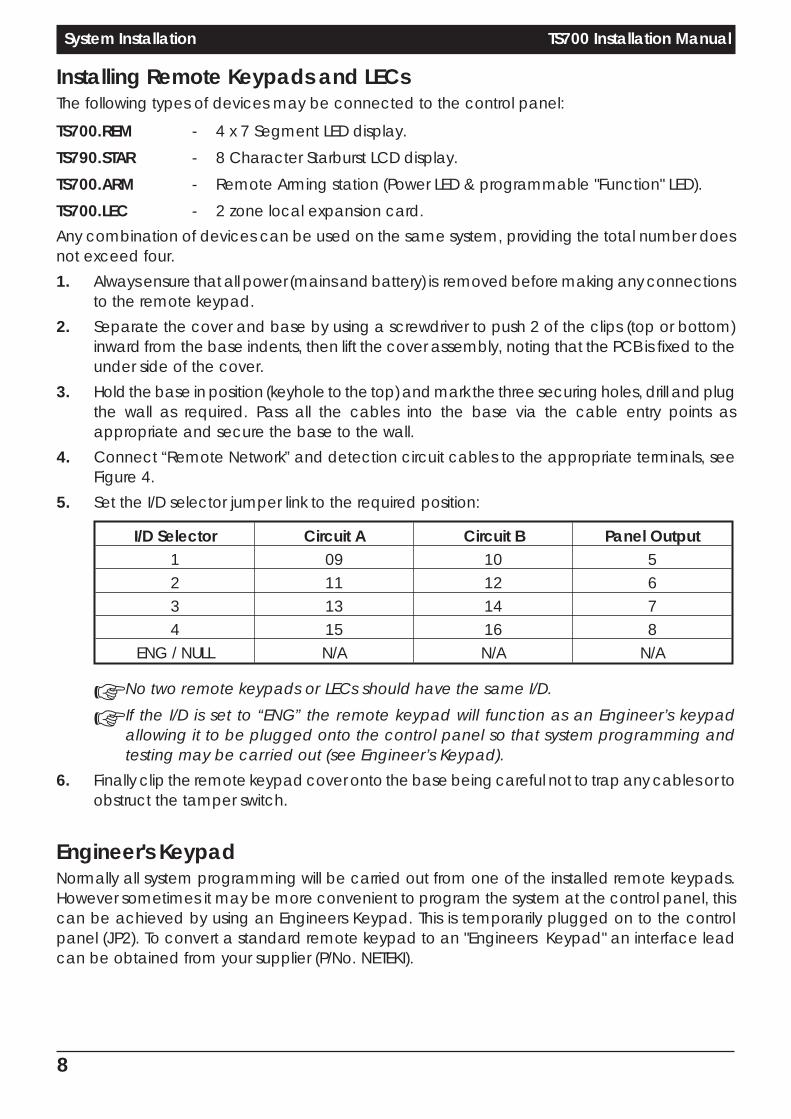
Installing Remote Keypads and LECsThe following types of devices may be connected to the control panel:
TS700.REM - 4 x 7 Segment LED display.
TS790.STAR - 8 Character Starburst LCD display.
TS700.ARM - Remote Arming station (Power LED & programmable "Function" LED).
TS700.LEC - 2 zone local expansion card.
Any combination of devices can be used on the same system, providing the total number doesnot exceed four.
1. Always ensure that all power (mains and battery) is removed before making any connectionsto the remote keypad.
2. Separate the cover and base by using a screwdriver to push 2 of the clips (top or bottom)inward from the base indents, then lift the cover assembly, noting that the PCB is fixed to theunder side of the cover.
3. Hold the base in position (keyhole to the top) and mark the three securing holes, drill and plugthe wall as required. Pass all the cables into the base via the cable entry points asappropriate and secure the base to the wall.
4. Connect “Remote Network” and detection circuit cables to the appropriate terminals, seeFigure 4.
5. Set the I/D selector jumper link to the required position:
I/D Selector Circuit A Circuit B Panel Output1 09 10 52 11 12 63 13 14 74 15 16 8
ENG / NULL N/A N/A N/A
☞ No two remote keypads or LECs should have the same I/D.
☞ If the I/D is set to “ENG” the remote keypad will function as an Engineer’s keypadallowing it to be plugged onto the control panel so that system programming andtesting may be carried out (see Engineer’s Keypad).
6. Finally clip the remote keypad cover onto the base being careful not to trap any cables or toobstruct the tamper switch.
Engineer's KeypadNormally all system programming will be carried out from one of the installed remote keypads.However sometimes it may be more convenient to program the system at the control panel, thiscan be achieved by using an Engineers Keypad. This is temporarily plugged on to the controlpanel (JP2). To convert a standard remote keypad to an "Engineers Keypad" an interface leadcan be obtained from your supplier (P/No. NETEKI).
8
System Installation TS700 Installation Manual

9
TS700 Installation Manual System Installation
RemoteNetwork
Spare Core
Control Panel
Power fordetectors
Power fordetectors
Power fordetectors
Power fordetectors
I/D=2I/D=1 I/D=3 I/D=4RemoteKeypador LEC
A B C D E
RemoteKeypador LEC
A B C D E
RemoteKeypador LEC
A B C D E
RemoteKeypador LEC
A B C D E
A
B
C
D
E
100m (Max.)
+ + + +
Figure 4. Remote Keypad & LEC connections
Programmable outputswitched -ve@ 100mA
Remote networkconnections
= Disabled
2 Detectioncircuits
I/DSelector
TamperSwitch
A B C D E O/P-
LCD Module
2 Detectioncircuits
Programmable outputswitched -ve
@100mA
I/DSelector
TamperSwitch
A B C D E O/P-
Remote networkconnections
LED Module
TS700 LED Remote Keypad TS790 STAR Remote Keypad
Figure 5 TS700 & TS790 STAR Remote Keypads

Installing a Plug-on Digicom1. A digicom type DC54 or DC58 can be fitted in the base of the TS700 main panel. The unit
should be fitted in accordance with the installation instructions supplied with it andconnected to JP3.
2. The alarm channels for the plug-on digicom are programmed as required (page 16). It willbe necessary to fit a programmed NVM in the digicom or to program it in accordance withthe instructions supplied with the unit.
Installing a stand-alone Digicom or RedCAREA stand-alone digital communicator, Red CARE STU or Paknet interface card can be connectedto the system to transfer panel alarm status information to a dedicated alarm receiving centre. Thecontrol panel has the following connections (Figure 6) for a digicom etc.
1 to 8 - These are the programmable digicom outputs. They are normally at +12Vand switch to 0V when active.
+DC POWER - This provides a permanent +12V power to the digicom. The output isun-fused and therefore should only be used if the digicom is fitted insidethe control panel.
LINE FLT - When this input is switched to +12V a telephone line fault condition will begenerated.
10
System Installation TS700 Installation Manual
ControlPanel
3GSTU
1
1
+DC POWER
Program
As:-
Open (08)
Alarm (05)
PA (06)
Fire (07)
LINE FLT
AUX 0V
2
2
3
3
4
4
5
TB
1
Channel Inputs areProgrammed asPositive Removed
TB
2T
B3
TB
4
Co
ntro
l
Lin
e
Fa
ult
RP
S
5
6
6
7
7
0V
NO
NO
NO
NC
NC
NC
8
8
CC
CA
+A
+A
+A
+V
+
Figure 6. 3GSTU RedCARE Connections

Sounder ConnectionsThe external and internal sounder can be connected to the control panel using the followingconnections:
AUX TAMP - These terminals provide tamper protection to auxiliary devices such aspower supplies, extension loudspeaker units etc.
SPK+ - Extension loudspeakers may be connected between [SPK+] and [H/O-].The minimum impedance is 16 Ohms. Up to two may be connected to thecontrol panel.Do NOT run extension loudspeakers within the same cabling as remotekeypads or LECs.
H/O - - This is used to provide a permanent -ve hold off to external sounders.
H/O + - This is used to provide a permanent +ve hold off to external sounders,strobes etc. It is protected by a 1 Amp fuse (Bell 12V).
TR - - This is the negative tamper return connection from the siren or bell.
STB - - This is the strobe output which will switch to 0V on alarm and draws amaximum of 500mA. Connect the other side of the strobe to the [H/O+].
TRG - - This output can be programmed to be either an SAB or SCB and operatesas follows:SAB: TRG - will switch to 0V on alarm and will sink a maximum of 500mA.SCB: TRG - will provide a negative hold off, which is removed on alarm.
11
TS700 Installation Manual System Installation
TypicalExternal Sounder
ControlPanel
H/O - 0V
H/O + +12V
Tamper InTR -
STB - Tamper Out
TRG - Strobe +ve
Strobe -ve
Trigger -ve
Figure 7. External and Internal Sounder Connections

Installing Output ModulesOutput modules (CPA6.OM) can be used to provide an output to a set of LEDs to indicate circuitactivations (mimic). Output modules will normally be fitted inside the equipment they arecontrolling and can be positioned up to 500 metres away from the main panel. They may be fittedinside the TS700 by fitting posts and securing them to the base. The output module should be usedand connected in accordance with the output module instructions provided (Figure 8).
Connecting a PrinterThe printer model type CPA6.P (obsolete) may be directly plugged on to the control panel pluglabelled PRINTER. Alternatively other models such as the DATAC or any standard RS232 serial printercan be connected to the control panel via a MPA/DCI. Menvier Security supply a DATAC printer kitwhich consists of a portable RS323 printer, charger and DCI. The DCI can be purchased separatelyif you require to source your own RS232 printer.
12
System Installation TS700 Installation Manual
PL1
1k Resistors
LED's
1 2 3 4 5 6 7+
12V
IN
+12V
OU
T
+12V
OU
T 8
PL2
To next OM
Connect to pluglabelled OUTPUTMODULE
100m
Figure 8. Output Module Connections
MPAor DCI
DATAC or RS232 printer
CPA6 Printer
RS232 Data
Connect to JP1PRINTER
Connect to JP1PRINTER
11
CPA6 PCPA6 P
DATA IN
POWERPAPER FEED
PRINTER SETUPBaud RateParityStop BitsData BitsDTR
= 4800= None= 2= 8= Normal
Figure 9. Datac Printer Set-up and Connections

Programmable OutputsThe TS700 has many programmable outputs which can be used to drive relays, LED’s etc. Eachoutput can be programmed for a different function, see "Programmable Output Types" on page17.
Control Panel OutputsThe control panel has four high current programmable outputs:
[-1] - Switched -ve output rated at 500mA.
[-2] - Switched -ve output rated at 500mA.
[+3] - Switched +ve output rated at 500mA.
[+4] - Switched +ve output rated at 500mA.
Remote keypads & LEC OutputsEach remote keypad and TS700 LEC has one programmable output:
[O/P] - Switched -ve output rated at 100mA.
13
TS700 Installation Manual System Installation
RelayRelay
SmokeDetector
SmokeDetector
Relay available fromRS componentsP/No. 346-946.Capable of switchingmains voltages
Relay available fromRS componentsP/No. 346-946.Capable of switchingmains voltages
+ 12 V + 12 V
+ve Outputs -ve Outputs
0V 0V
Diode (IN418)Diode (IN418)
Figure 10. Programmable Outputs Wiring Examples

Pre Power-Up ChecksOnce the system is installed, but prior to powering-up give the system one final check to ensurethat:
1. The wiring conforms to the requirements detailed in this manual and that all interconnectionsare correct (A to A, B to B etc.).
2. All system cables are kept clear of mains supply cables, telephone cables and R.F. cables. Itis recommended that cable ties be used to keep cables separated.
3. Verify that maximum cable lengths and resistances are not exceeded.
4. Mains power supply cables to the system are connected to an un-switched fused spur.
5. Grommets are used where cables enter metal housings to ensure that insulation is notcompromised.
Initial Power-UpTo power the system for the first time:
1. Place a small screwdriver blade between the pins on the control panel PCB, marked"FACTORY RESET". This will ensure the factory default parameters are set (see Table 1).
2. Switch on the 240V mains supply and remove screwdriver blade.
3. Check that power LED on the control panel PCB is illuminated.
4. Check that the remote keypads display "LT" (Panel Lid tamper). The remote keypadsounders and extension loudspeakers will operate.
5. Enter the engineers passcode (default 1234) to silence the sounders.
6. Connect the standby battery.
Power-Up ChecksWhen the initial power-up checks have been completed, check the following:
1. Using a voltmeter measure the DC voltage at each remote keypad and ensure the voltage isgreater than 11V whilst running on the system standby battery.
2. Using a voltmeter measure the DC voltage between mains earth and +12V, and the voltagebetween mains earth and 0V. In both cases the measurement should be 1V or less. If theVoltage is greater than 1V, the system has an "Earth Fault" and all cables should be checkedfor isolation to earth.
3. Using a voltmeter set to a low DC voltage range, measure the voltage across the controlpanel PCB test point (V). To calculate the system current consumption multiply the reading byten, e.g., a reading of 70mV = 700mA. Ensure that the reading is not greater than 1.0A.
4. Repeat test (3) with the system in an alarm condition and ensure that the reading is notgreater than 1.0A.
5. The system is now ready to be programmed see "Programming".
14
System Installation TS700 Installation Manual

Factory Default Parameters
Engineer's code 1234
Master Usercode
5678
Panel andRemote Outputs
1 2 3 4 5 6 7 8
Walk Test CourtesyLight
Switched12V
DetectorReset
CodeAccepte
d
CodeAccepte
d
CodeAccepte
d
CodeAccepte
d
Digicom Outputs& Channels
1 2 3 4 5 6 7 8
Fire PA Alarm Set Eng onSite
Bell On Tamper SecondAlarm
DetectionCircuits
01: Final Exit 02: Night (access) 03-06: Night 07: Exit Terminator
08: PA Audible 09: Final Exit 10: PA Audible 11-16:Not Used
System Timers
0 1 2 3
ACPO Delay0 seconds
No Re-arms0
Settling Time07 seconds
Digicom Delay0 Seconds
4 5 6 7
Exit Time30 Seconds
Entry Time30 Seconds
Bell Duration20 Minutes
Bell Delay0 Minutes
8 9
Double Knock0 Seconds
Test Time14 Days
Setting ModesFull Set
Final ExitPart Set ATimed Exit
Part Set BTimed Exit
Part Set CTimed Exit
Reset Algorithm 004
SystemConfiguration
0 1 2 3
Bell output is SAB User 1 has accessto all user menus
Fire signalled at alltimes
24 Hour circuits areaudible
4 5 6 7
bell is delayed for30 seconds in part
set
Alarm output iscleared on reset
Setting with line faultor mains failure is
allowed
System reset by user
8 9
Continuous entryand exit tones
Engineer code onlyfor access to
engineer menus
Table 1. Factory Default Parameters
15
TS700 Installation Manual System Installation

Programming
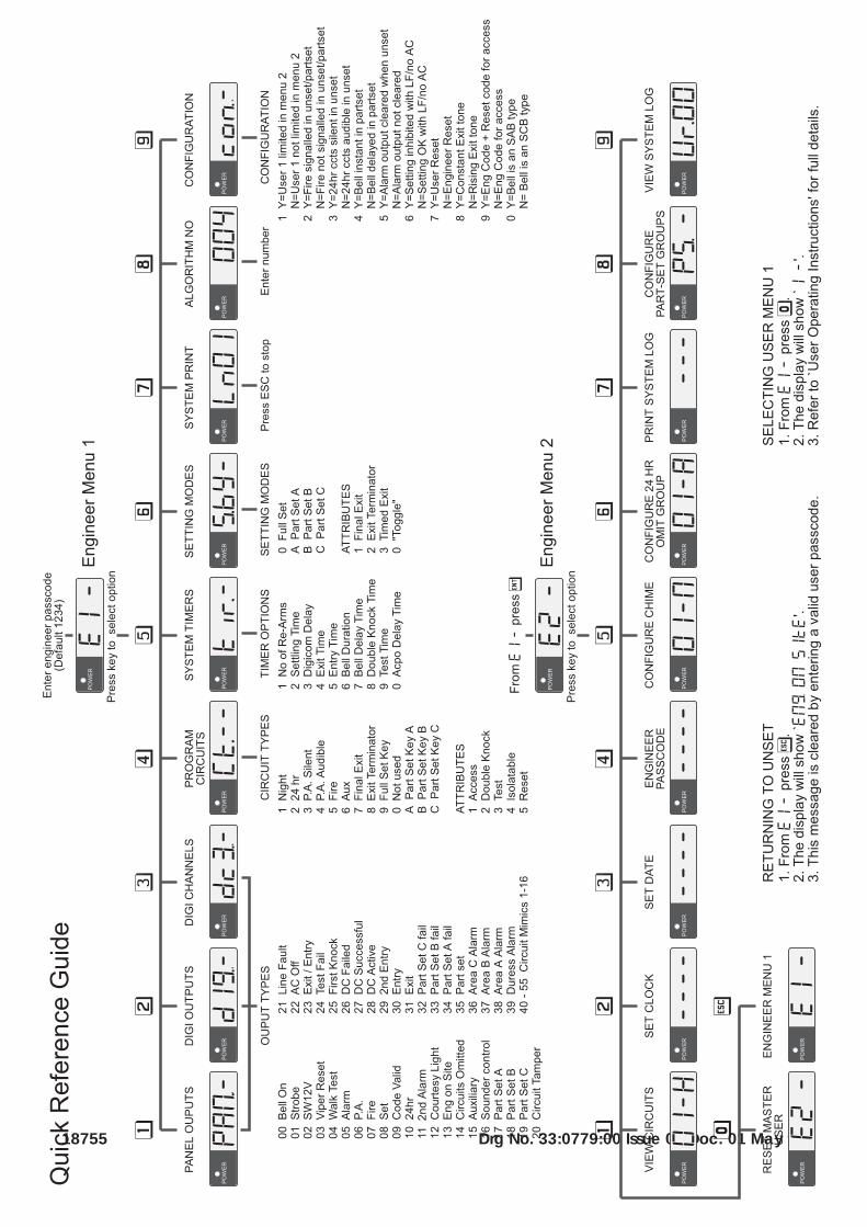
Engineer Menu 1Engineers menu 1 is selected when the engineer's passcode is entered during the unset condition.There are nine programming options which may be selected in any order. The engineer mayleave engineer menu 1 by pressing the [ESC] key. The system will return to the unset condition butthe remote keypads will show: "ENG ON SITE". This message will be cleared the next time a validuser passcode is entered.
Panel OutputsOutputs 1 to 4 for the control panel and 5 to 8 for the remote keypads can be programmed to anyof the output function types 0 to 55 as listed in Table 2 on page 15.
1. Ensure that "Engineer Menu 1" is selected.
2. Press 1 to select the Panel Outputs option.
3. The display will show: PAN.-
4. Enter the required output number 1 to 8.
5. The display will show the current output function (Table 2).
6. Enter the new function number and press [.
7. The display will return to step 3. Repeat steps 4 to 7 for theremaining outputs.
8. Press ] to return to "Engineer Menu 1".
Digicom OutputsThe eight switched -ve Digicom outputs 1 to 8 may be connected to the Digicom channel inputs.The outputs may be programmed to any of the function types 0 to 55 (Table 2).
1. Ensure that "Engineer Menu 1" is selected.
2. Press 2 to select the Digicom Outputs option.
3. The display will show: DIG.-
4. Enter the required digicom output number 1 to 8.
5. The display will show the current output function (Table 2).
6. Enter the new function number and press [.
7. The display will return to step 3. Repeat steps 4 to 7 for theremaining digicom outputs.
8. Press ] to return to "Engineer Menu 1".
Plug-on Digicom ChannelsThe eight channels for the plug-on digicom may be programmed to any of the function types 00to 55 (Table 2). The procedure is similar to programming the digicom outputs (above).
1. Follow above procedure, except press 3 at step 2.
16
Programming TS700 Installation Manual
POWER PAN.-Enter panel output 1 - 4 orremote output 5 - 6.
POWER 04Enter new output type 00 - 55(see Table 2.)
POWER DIG.-Enter digicom output 1 - 8.
POWER 04Enter new output type 00 - 55(see Table 2.)
POWER Dc3.-Enter digicom output 1 - 8.

No Type Function00 Bell On Active when the external Bell trigger is activated.
01 Strobe Active when the Strobe trigger is activated.
02 SW12 Used to latch devices in an alarm. Active when the system is set.
03 Detector Reset Used to power devices which require power to be removed to reset them.
04 Walk Test Active when a Walk Test is in progress.
05 Alarm Active when intruder alarm is present.
06 PA Active when a PA alarm is present.
07 Fire Active when a Fire alarm is present.
08 Set Active when the system is Set.
09 Code Accepted Active for 10 seconds when any valid passcode is entered.
10 24 Hour Active when a 24 hour circuit is in alarm.
11 Second Alarm Active when a second circuit causes an alarm, use for ALARM CONFIRMATION.
12 Courtesy Light Active when any keypad is in use.
13 Engr on Site Active when the engineer's passcode is entered until a User passcode is entered.
14 Ccts Omitted Active when circuits are omitted.
15 Auxiliary Active when an Auxiliary circuit is in alarm.
16 Sndr Control Can be used as the 0V connection to an extension loudspeaker so that thesounder is muted during keypad entries. Only suitable for panel outputs 1 & 2.
17 Area Set A Active when area A is Set.
18 Area Set B Active when area B is Set.
19 Area Set C Active when area C is Set.
20 Tamper Active when a Aux, or circuit tamper is triggered.
21 Line Fault Active when a digicom telephone line fault occurs.
22 Mains Off Active when mains power is removed.
23 Exit/Entry Active during exit and entry.
24 Test Fail Active when a circuit on Test is activated.
25 First Knock Active when a double knock is activated for the first time.
26 DC Failed Active if the digicom fails to communicate.(plug-on)
27 DC Successful Active when the digicom sends a message and it is acknowledged. (plug_on)
28 DC Active Active while the digicom is triggered.(plug-on)
29 Second Entry Active when the second entry timer is started.
30 Entry Active when the system is set or part set and the entry route is in use.
31 Exit Active when the system exit procedure is started.
32 Part Set C fail Active when Part Set area C fails to set.
33 Part Set B fail Active when Part Set area B fails to set.
34 Part Set A fail Active when Part Set area A fails to set.
35 Part Set Active when ever the system is Part Set.
36 Area C Alarm Active when Area C Alarms.
37 Area B Alarm Active when Area B Alarms.
38 Area A Alarm Active when Area A Alarms.
39 Duress Alarm Active when a duress code is entered at a keypad.
40- 55 Circuit mimic Will mimic (active when circuit is active) circuits 1 to 16 respectively .
Table 2. Programmable Output Functions
17
TS700 Installation Manual Programming
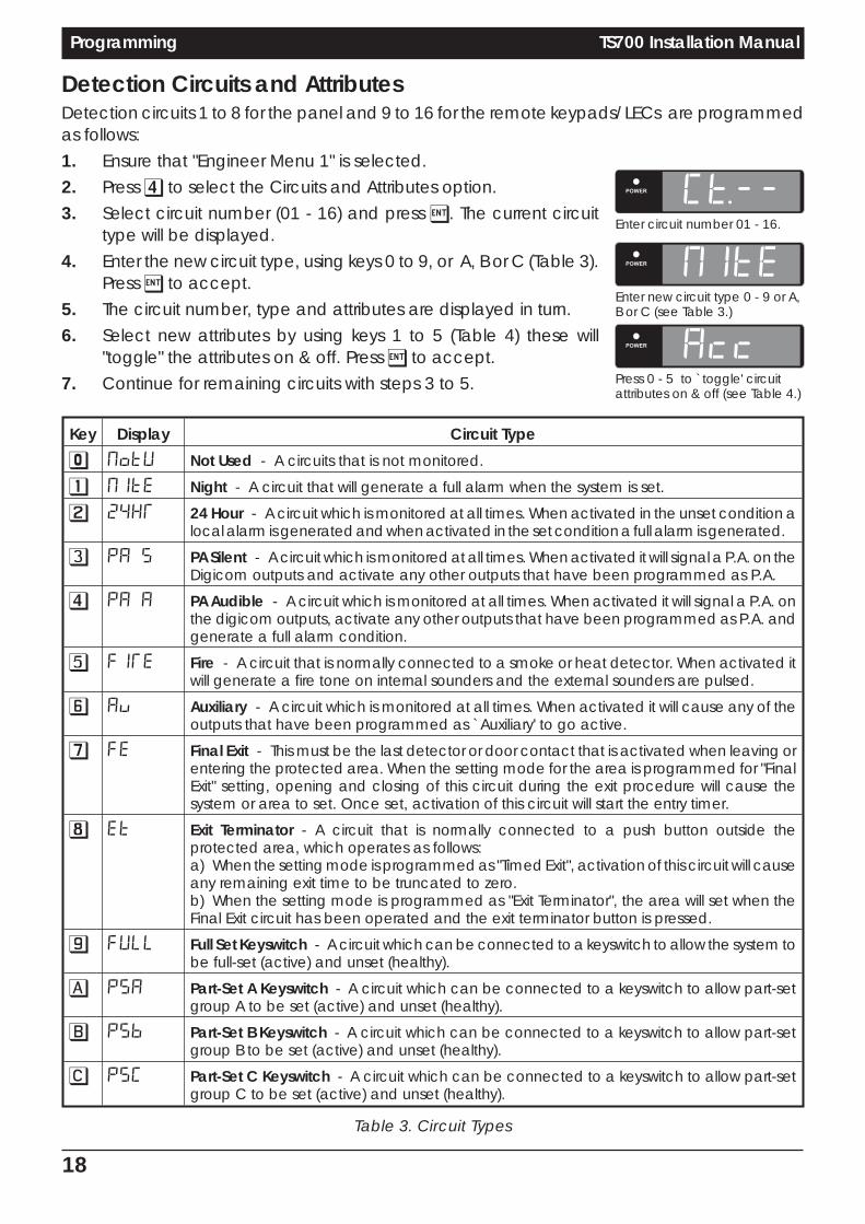
Detection Circuits and AttributesDetection circuits 1 to 8 for the panel and 9 to 16 for the remote keypads/ LECs are programmedas follows:
1. Ensure that "Engineer Menu 1" is selected.
2. Press 4 to select the Circuits and Attributes option.
3. Select circuit number (01 - 16) and press [. The current circuittype will be displayed.
4. Enter the new circuit type, using keys 0 to 9, or A, B or C (Table 3).Press [ to accept.
5. The circuit number, type and attributes are displayed in turn.
6. Select new attributes by using keys 1 to 5 (Table 4) these will"toggle" the attributes on & off. Press [ to accept.
7. Continue for remaining circuits with steps 3 to 5.
Key Display Circuit Type
0 NoTU Not Used - A circuits that is not monitored.
1 NITE Night - A circuit that will generate a full alarm when the system is set.
2 24HR 24 Hour - A circuit which is monitored at all times. When activated in the unset condition alocal alarm is generated and when activated in the set condition a full alarm is generated.
3 PA S PA Silent - A circuit which is monitored at all times. When activated it will signal a P.A. on theDigicom outputs and activate any other outputs that have been programmed as P.A.
4 PA A PA Audible - A circuit which is monitored at all times. When activated it will signal a P.A. onthe digicom outputs, activate any other outputs that have been programmed as P.A. andgenerate a full alarm condition.
5 FIRE Fire - A circuit that is normally connected to a smoke or heat detector. When activated itwill generate a fire tone on internal sounders and the external sounders are pulsed.
6 Au Auxiliary - A circuit which is monitored at all times. When activated it will cause any of theoutputs that have been programmed as `Auxiliary' to go active.
7 FE Final Exit - This must be the last detector or door contact that is activated when leaving orentering the protected area. When the setting mode for the area is programmed for "FinalExit" setting, opening and closing of this circuit during the exit procedure will cause thesystem or area to set. Once set, activation of this circuit will start the entry timer.
8 ET Exit Terminator - A circuit that is normally connected to a push button outside theprotected area, which operates as follows:a) When the setting mode is programmed as "Timed Exit", activation of this circuit will causeany remaining exit time to be truncated to zero.b) When the setting mode is programmed as "Exit Terminator", the area will set when theFinal Exit circuit has been operated and the exit terminator button is pressed.
9 FULL Full Set Keyswitch - A circuit which can be connected to a keyswitch to allow the system tobe full-set (active) and unset (healthy).
A PSA Part-Set A Keyswitch - A circuit which can be connected to a keyswitch to allow part-setgroup A to be set (active) and unset (healthy).
B PSB Part-Set B Keyswitch - A circuit which can be connected to a keyswitch to allow part-setgroup B to be set (active) and unset (healthy).
C PSC Part-Set C Keyswitch - A circuit which can be connected to a keyswitch to allow part-setgroup C to be set (active) and unset (healthy).
Table 3. Circuit Types
18
Programming TS700 Installation Manual
POWER CT.--Enter circuit number 01 - 16.
POWER NITEEnter new circuit type 0 - 9 or A,B or C (see Table 3.)
POWER AccPress 0 - 5 to `toggle' circuitattributes on & off (see Table 4.)

Key Display Attribute Type1 Acc Access - Circuits programmed with this attribute are automatically isolated during the
entry procedure to allow a "walk through" route for the user to access the remote keypad.When the system is part set activation of a circuit with the "Access" attribute will start the entrytimer. The Access attribute may only be assigned to Night circuit types.
2 2AcT Double Knock - Circuits programmed with this attribute will only cause an alarm if:a) The circuit is activated twice within the Double Knock window (this time may be set in theSystem Timers menu).b) The circuit remains active for the whole duration of the Double Knock window.The Double Knock attribute may only be assigned to Night, 24hr and Auxiliary circuit types.
3 TEST Test - Circuits with this attribute will be disabled from the system for the period set by the"Test Time" (see System Timers). If the circuit is activated during this period the activation willbe logged and the user is informed of the circuit failure when trying to set the system. Thetest fail message may only be cleared with the engineer's passcode. If at the end of the testperiod no activations have occurred the circuit is automatically removed from test andbehaves as normal. The test period is initiated by entering the engineer's passcode. The testattribute may only be assigned to Night, 24hr, PA Silent, PA Audible, Fire and Auxiliary circuittypes.
4 ISOL Isolate - Circuits with this attribute are allowed to be omitted by the user when setting thesystem. The isolate attribute may only be assigned to Night, 24hr and Auxiliary circuit types.
5 RST Reset - This attribute is normally assigned to a circuit that is connected to a Vibration orSmoke detector, so that during the "Detector Reset" period the circuit is not monitored. TheReset attribute may only be assigned to Night, 24hr, Fire and Auxiliary circuit types.
Table 4. Circuit Attributes
System TimersThere are ten separate system timers which are shown in Table 5a and 5b.
1. Ensure that "Engineer Menu 1" is selected.
2. Press 5 to select the System Timers option.
3. The display will show: Tir.-
4. Enter the required timer number 0 to 9.
5. The display will show the current timer setting.
6. Enter the new timer value and press [.
7. The display will return to step 3. Repeat steps 4 to 7 for theremaining outputs.
8. Press ] to return to "Engineer Menu 1".
Key Timer Range Function
0 ACPO Delay 0-199 sec For ACPO requirements this timer is normally set to 90 seconds. If during theentry procedure the user deviates from the entry route and causes analarm, the communication of the alarm signal to the central station isdelayed by this timer.
1 Re-Arms 0-199 At the end of the bell duration time the system re-arms all circuits that arehealthy. Circuits that are still in an alarm are isolated until they change to ahealthy condition. This timer controls the number of times that a circuit willre-arm before it is locked out of the system.
Table 5a. System Timers
19
TS700 Installation Manual Programming
POWER Tir.-Enter timer number 0 - 9. (seeTable 5a & 5b)
POWER 030Enter timer value 000 -199. (seeTable 5a & 5b)

2 Settling Time 0-199 sec When setting the system by "Final Exit" or "Exit Terminator", detectors that areon the exit route sometimes take 3-4 seconds to settle after activation. Thedelay programmed in this timer is used to allow these detectors to settlebefore the system or area is set.
3 Digicom Delay 0-199 sec When the system is part-set the communication of an alarm signal to thecentral station may be delayed by the value set in this timer.
4 Exit Time 0-199 sec This timer sets the delay between the user initiating the exit procedure andthe system (or area) actually Setting. If during the exit time an Exit Terminatorcircuit is activated the exit time is cancelled and the system setsimmediately.
5 Entry Time 0-199 sec The time allowed for entering the protected premises via the entry routewhen the system is (Part) Set . The time is allocated to two entry periods. Awarning is given if the first is exceeded and a full alarm occurs if the secondis exceeded.
6 Bell Duration 0-199 min The duration time of the bell and sounders when an alarm occurs.
7 Bell Delay 0-199 min This timer delays the activation of the bell output and internal sounders.
8 Double Knock 0-199 sec This is the Double Knock time window in which either:Two circuit activation must occur within this time to generate an alarmcondition. Or the circuit must remain active for the whole duration of thistime to generate an alarm condition. This will only apply to circuits with theDouble Knock attribute
9 Test Time 0-30 days This timer varies the number of days that Test attribute may be applied to acircuit. If the time is set to 000 then circuits will remain on test until the "Test"attribute is removed.
Table 5b. System Timers
Setting ModesThe system may be set by one of the following modes:
Final Exit - The system or area will set when the "Final Exit" circuit is activated and afterthe "Settle Time" has expired.
Exit Terminator - The system or area will set when the "Final Exit" circuit is activated, the "ExitTerminator" button is pressed and after the "Settle Time" has expired.
Timed Exit - The system or area will set when the "Exit Time" has expired or if the "ExitTerminator" button is pressed.
The setting mode for full-set, part-set groups A, B and C are programmed as follows:
1. Ensure that "Engineer Menu 1" is selected.
2. Press 6 to select the Setting Modes option.
3. The display will show: S.BY-
4. Select setting group by pressing:
0 for full-set
A for part-set group A
B for part-set group B
C for part-set group C
5. The display will show the current setting mode.
20
Programming TS700 Installation Manual
POWER S.BY-Enter setting group 0,A,B or C.
POWER F-FEEnter setting mode 1,2,3 or 0.

6. Select new setting mode by pressing:
1 for Final Exit
2 for Exit Terminator
3 for Timed Exit
0 to `toggle' between all three options
7. When the display shows the required setting press [ to accept.The display will return to step 3. Repeat steps 4 to 7 for theremaining setting groups.
8. Press ] to return to "Engineer Menu 1".
+ When using part set codes to set areas, the first area that is set will follow the setting modedefined by that area. Any subsequent areas will always use the timed exit method.
System PrintA print-out of all system parameters may be obtained so that a permanent record of the systemprogram details may be kept.
1. Ensure that "Engineer Menu 1" is selected.
2. Press 7 to select the System Print option.
3. The display will show the line that is being printed (Ln01).
4. Press ] to stop printing and return to "Engineer Menu 1".
Remote Reset AlgorithmWhen the system requires an Engineer Reset this may be over ridden by using the Remote Resetfacility. To provide additional security the way in which the "Reset Code" is generated can beselected to be one of 199 algorithms (default=004).
1. Ensure that "Engineer Menu 1" is selected.
2. Press 8 to select the Reset Algorithm option.
3. The display will show the current setting.
4. Enter the new number and press [ to accept.
System ConfigurationThere are ten system configuration options which are shown in Table 6.
1. Ensure that "Engineer Menu 1" is selected.
2. Press 9 to select the System Configuration option.
3. The display will show: con.-
4. Enter the required configuration number 0 to 9.
5. The display will show the current setting. Press 0 to "toggle"between YES and NO. Press [ to accept.
6. The display will return to step 3. Repeat steps 4 to 6 for theremaining system configuration options.
7. Press ] to return to "Engineer Menu 1".
21
TS700 Installation Manual Programming
POWER Ln01Press ESC to cancel printing.
POWER 004Enter new number 000 - 199.
POWER con.-Enter configuration number 0- 9(see Table 6).
POWER YESPress 0 to `toggle' the optionbetween YES or NO.(see Table 6).

Key YES NO
0 Bell output is set for SAB Bell output is set for SCB
1 Disable Master User from menu 2 options 4-9 Master user has access to all options in menu 2
2 Fire Signalled when Unset/Part Set/Full Set Fire signalled only when full Set
3 24hour circuits silent when Unset 24hour circuits audible when Unset
4 Bell is instant when Part Set Bell is delayed when Part Set (30 secs)
5 Alarm output (05) cleared when system is unset Alarm output cleared when system is reset
6 Setting inhibited with line fault/no mains power Setting allowed with line fault/no mains power
7 System reset by User or Engineer System reset by Engineer or Remote Reset
8 Continuous Entry and Exit tones Rising Entry and Exit tones
9 Engr & Remote Reset code to gain access to E1/E2 Engr code gains access to E1 and E2 menus
Table 6. System Configuration options
Engineer's Menu 2This menu is selected by pressing the [ENT] key whilst "Engineers menu 1" is selected. There are tenprogramming options within this menu, which can be selected in any order. The engineer canleave this menu and return to "Engineers Menu 1" by pressing the [ESC] key.
View CircuitsThis option allows the engineer to view the status of each detection circuit. The circuit statusconditions are H=Healthy, A=Active, S=Shorted or T=Tamper.
1. Ensure that "Engineer Menu 2" is selected.
2. Press 1 to select the View Circuits option.
3. The circuit status will be displayed.
4. Select circuits either by entering the number or by pressing [ toscroll through the circuits.
5. Press ] to abandon and return to "Engineer Menu 2".
Change TimeThe system clock may be changed using 24 hour clock format.
1. Ensure that "Engineer Menu 2" is selected.
2. Press 2 to select the Change Time option.
3. Enter the time in 24 hour notation (e.g., 1805).
4. Press [ to accept.
22
Programming TS700 Installation Manual
POWER 03-HCircuit 03 is Healthy.
POWER 03-ACircuit 03 is Active.
POWER ----Enter time in 24 hour format.
POWER 1805Time entered 1805 (6:05 pm.)

Change DateThe system calendar may be changed by entering the date as four digits representing the dayand month e.g., 0207 is the 2nd July.
1. Ensure that "Engineer Menu 2" is selected.
2. Press 3 to select the Change Date option.
3. Enter the date as four digits.
4. Press [ to accept.
Change Engineer's PasscodeThe factory default engineer's passcode is set to 1234, but the installation engineer should changethis to their own personal four-digit passcode, as follows:
1. Ensure that "Engineer Menu 2" is selected.
2. Press 4 to select the Change Engineer's Passcode option.
3. Enter the new passcode then press [ to accept.
4. A high tone will indicate acceptance. A low tone sound willindicate that the passcode is not available.
Configure Chime CircuitsThis option is used to select the circuits that will chime.
1. Ensure that "Engineer Menu 2" is selected.
2. Press 5 to select the Chime Circuits option.
3. Circuits will be displayed as Y(Yes) to chime or N(No) not tochime. Change status by pressing 0 ("toggle" action).
4. Press [ to accept (high tone) and go to next circuit. Circuits maybe selected by number. Press ] to quit.
Configure 24 Hour Omit GroupThis option allows the engineer to select the 24 hour circuits that will be omitted when the 24 houromit option is selected in "User Menu 1" option 6.
1. Ensure that "Engineer Menu 2" is selected.
2. Press 6 to select the 24hour Omit Group option.
3. Circuits will be displayed as O(Omitted) or A(Armed). Press 0 tochange ("toggle" action).
4. Press [ to accept (high note) and go to next circuit. A low toneindicates that the circuit cannot be omitted.
5. Circuits may be selected by number. Press ] to quit.
23
TS700 Installation Manual Programming
POWER 01-NCircuit 01 will not chime.Press 0 to change.
POWER 01-YCircuit 01 will chime.Press ENT to accept.
POWER 02-ACircuit 02 will remain Armed.Press 0 to change.
POWER 02-OCircuit 02 will be Omitted.Press ENT to accept.
POWER ----Enter new engineer passcode.
POWER 2804New passcode 2804 entered.Press ENT to accept.
POWER ----Enter date (day & month).
POWER 0207Date entered 0207 (02 July).

Print System LogA printer may be connected to produce a print-out of the last 200 system events.
1. Ensure that "Engineer Menu 2" is selected.
2. Press 7 to select the Print Log option.
3. Enter the number of events to be printed.
4. Press [ to start printing. To stop printing select the menu againand enter 000 as the number of events to be printed.
Configure Part-Set GroupsWhen the system is part-set certain circuits are omitted. This option allows the engineer to selectthose circuits to be omitted when part-set A or B or C is selected.
1. Ensure that "Engineer Menu 2" is selected.
2. Press 8 to select the Part-Set Groups option.
3. Select the part-set group A or B or C.
4. Circuits will be displayed as O(Omitted) or A(Armed). Press 0 tochange ("toggle" action).
5. Press [ to accept displayed status (high tone) and go to nextcircuit. Circuits may be selected by number.
6. Press ] to return to step 3 and ] again to return to "EngineerMenu 2".
View System LogThe time, date and nature of the last 200 events on the system may be viewed starting with themost recent event.
1. Ensure that "Engineer Menu 2" is selected.
2. Press 9 to select the View Log option.
3. The most recent event will be displayed (see Table 7)
4. Press A to scroll back and C to scroll forward. Press B to show thetime of the event (first press), the date (second press) the time inminutes and seconds (third press).
5. Press ] to abandon.
Reset Master User 1This option allows the engineer to reset the master user passcode back to the factory default code`5678'. This feature is useful when the master user has forgotten their passcode or has inadvertentlychanged it.
1. Ensure that "Engineer Menu 2" is selected.
2. Press 0 to Reset User 1.
24
Programming TS700 Installation Manual
POWER CA.01Log event showing `CircuitAlarm 01'. Press A to scroll backor C to scroll forward. Press B toview time and date.
POWER 01-ACircuit 01 will remain Armed.Press 0 to change.
POWER 01-OCircuit 01 will be Omitted.Press ENT to accept.
POWER PS -Enter part-set group A, B or C.
POWER ---Enter the number of events tobe printed. Press ENT to start.

AA Action Alarm (Alarm output activated) LT Lid Tamper or SAB tamper
Ac** Access Passcode (User code **enteredwith the last two digits reversed)
OP System Open (unset)
AD.** Alarm Delayed (the system is part set andcircuit ** was activated)
Or Omits Removed
Au.** Auxi l iary Alarm (ci rcui t number**activated)
PA.** PA Alarm (from circuit number **)
BF Battery Fault (battery voltage below 10.5V) PF Power Failure (remote power LED flashes)
BT Bell Test Pr Power Restored
CA.** Circuit Alarm (from circuit number **) PS.* Part Set (area *)
cc Communication Complete (Plug-on only) PT.** Code Tamper (from remote keypad **)
cF Communication Failed (plug-on only) rA System re-armed
CI Circuits Isolated (24 hour circuits) rc System reset by REMOTE CODE RESET
CO.** Circui ts Omit ted (ci rcui t number**omitted)
rr.** Remote Keypad ** removed
Dc Date Changed rT.** Remote Keypad ** case tamper
DF Default User code 1 to 5678 SF System Failed to Set
Du.** Duress Alarm (from User code **) Sr System on-site reset (LK1 open on powerup)
EA.** Entry Alarm (from circuit number **) ST.* Area * Set (using area setting codes)
En.** Entry (from circuit number **) So.** Part set keyswitch ** operated
FA.** Fire Alarm (from circuit number **) TA.** Tamper Alarm (from circuit number **)
FB.** Fuse Blown (fuse number **) Tc Time Changed
Fn.** First Knock (from circuit number **) TF.** Circuit ** failed test
Fr Factory Reset (LK1 closed on power up) To All Test circuits removed from test
FS Full Set Un.* Area * unset (using area setting codes)
LB Low Battery Ur.** User Code ** entered
LF Telephone line fault -- No event
Lr Telephone line restored
Table 7. Event Log Codes
25
TS700 Installation Manual Programming

Appendices
Domestic Part-Set Application ExampleThe TS700 control panel can be configured so that only part of the system is armed. The followingexample illustrates how the TS700 alarm system is configured so that it protects different areas of athree bedroom detached house. Figure 11 shows the layout of the house and position of thedetection circuits and remote keypad.
26
Appendices TS700 Installation Manual
P
P
P
P
P
RK
C
C
C
S
C
C
CP
CP
RK
Key:
10
9
8
7
6
2
1
3
5
4
Bedroom 1
Bedroom 2Bathroom
Landing
Bedroom 3
Lounge
Garage
KitchenDining Room
Hall
Passive Infra-Red Detector
Magnetic Contact
Remote Keypad
Control Panel
RK
P
S Smoke detector
Figure 11. A typical three bedroom house.
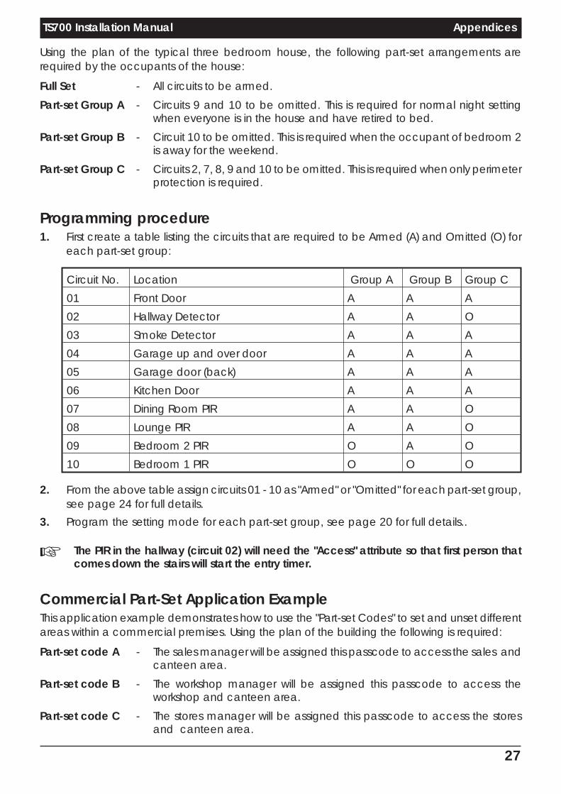
Using the plan of the typical three bedroom house, the following part-set arrangements arerequired by the occupants of the house:
Full Set - All circuits to be armed.
Part-set Group A - Circuits 9 and 10 to be omitted. This is required for normal night settingwhen everyone is in the house and have retired to bed.
Part-set Group B - Circuit 10 to be omitted. This is required when the occupant of bedroom 2is away for the weekend.
Part-set Group C - Circuits 2, 7, 8, 9 and 10 to be omitted. This is required when only perimeterprotection is required.
Programming procedure1. First create a table listing the circuits that are required to be Armed (A) and Omitted (O) for
each part-set group:
Circuit No. Location Group A Group B Group C
01 Front Door A A A
02 Hallway Detector A A O
03 Smoke Detector A A A
04 Garage up and over door A A A
05 Garage door (back) A A A
06 Kitchen Door A A A
07 Dining Room PIR A A O
08 Lounge PIR A A O
09 Bedroom 2 PIR O A O
10 Bedroom 1 PIR O O O
2. From the above table assign circuits 01 - 10 as "Armed" or "Omitted" for each part-set group,see page 24 for full details.
3. Program the setting mode for each part-set group, see page 20 for full details..
+ The PIR in the hallway (circuit 02) will need the "Access" attribute so that first person thatcomes down the stairs will start the entry timer.
Commercial Part-Set Application ExampleThis application example demonstrates how to use the "Part-set Codes" to set and unset differentareas within a commercial premises. Using the plan of the building the following is required:
Part-set code A - The sales manager will be assigned this passcode to access the sales andcanteen area.
Part-set code B - The workshop manager will be assigned this passcode to access theworkshop and canteen area.
Part-set code C - The stores manager will be assigned this passcode to access the storesand canteen area.
27
TS700 Installation Manual Appendices

The "Part-set Codes" A, B and C only affect the circuits assigned in their respective "Part-set Group'"i.e., "Part-set Code A" will set and unset the circuits assigned as "Omitted" in "Part-set Group A".
When configuring the TS700 system to use "Part-set Codes", it is important to think of the systemfrom the full-set state. When a part-set code is entered the circuits that have been assigned as"Omitted" for that "Part-set Group" will be unset. On re-entry of the "Part-set Code" the exitprocedure is started and at the end of the exit procedure the circuits that were "Omitted" arearmed again.
28
Appendices TS700 Installation Manual
Sales
Stores
P
C
Passive Infra-Red detector
Magnetic Contact
KEY:
RKRemote Keypad
CP Control Panel
P
Office
RKRK
RK
CanteenWorkshop
P
P
PP
P
P
CC
C C
C
CC
10812
11
1
2
34
5
6
13
14
7
9
CP
Figure 12. Commercial Premises

Programming procedure1. First, imagine the system is fully set. When "Part-set Code A" is entered certain circuits are
required to be "Omitted" whilst others remain "Armed". Create a table listing the circuits thatare to be "Omitted" (O) when "Part-set Code A" is entered. The circuits that will not be omittedmust therefore remain "Armed" (A). Then imagine the system is fully set again and repeat for"Part-set Codes" B and C.
Circuit No. Location Group A Group B Group C
01 Workshop PIR (1) A O A
02 Workshop Internal Door A O A
03 Workshop PIR (2) A O A
04 Sales Internal Door O A A
05 Canteen Door O O O
06 Canteen PIR O O O
07 Stores Internal Door A A O
08 Sales PIR O A A
09 Sales Office PIR O A A
10 Sales Entrance Door O A A
11 Workshop Entrance Door A O A
12 Workshop PIR (3) A O A
13 Stores Entrance Door A A O
14 Stores PIR A A O
2. From the above table assign circuits 01 - 14 as "Armed" or "Omitted" for each "Part-setGroup", see page 24 for full details.
3. Program the setting mode for each "Part-set Group", see page 20 for full details.
4. Program each "Part-set Code" with a four digit passcode, refer to the "User OperatingInstructions".
+ If a circuit is "Omitted" in more than one "Part-set Group" (circuits 05 and 06 in our example) itwill only be armed when all "Part-set Groups" are set. Using our example, if the system isunset and "Part-set Code A" is entered, the exit procedure is started and at the end of theexit procedure circuits 04, 08, 09 and 10 will be armed. The canteen detection circuits 05and 06 will remain unarmed until "Part-set Group" B and C are set (system full-set).
29
TS700 Installation Manual Appendices

Installation Record
Circuit Programming
No Location Type Access D-Knock Test Omit Reset PS A PS B PSC 24hr01
02
03
04
05
06
07
08
09
10
11
12
13
14
15
16
OutputsOutput 1 2 3 4 5 6 7 8
Panel & remotes
Digicom outputs
Digicom Channel
System TimersRe-arms: Settling: Digi Delay: Exit Time: Entry Time:
Bell Dur: Bell Delay: D-Knock: Test Time: ACPO:
Setting ModesFull-set Part-set A Part-set B Part-set C
System Configuration1: Yes / No 2: Yes / No 3: Yes / No 4: Yes / No 5: Yes / No
6: Yes / No 7: Yes / No 8: Yes / No 9: Yes / No 0: Yes / No
OtherAlgorithm No Remote Reset Tel No: Engineer:
Installation Company: Date:
Tel No:
30
Installation Record TS700 Installation Manual
18755 Drg No. 33:0779:00 Issue 07 Doc. 01 May 971 PA
N.-
2 DI
G.-
3 Dc
3.-
4 CT
.--
5 Ti
r.-
6 S.B
Y-
7 Ln
01
8
00
4
9 co
n.-
E1
-
Quic
kR
efe
rence
Guid
e
1 01
-H
2 --
--
3 --
--
4 --
--
5 01
-N
6 01
-A
7
--
-
8 PS
.-
9 Ur
.00
[
E2
-
0 E2
-
] E1
-
En
gin
ee
rM
en
u2
En
gin
ee
rM
en
u1
RE
TU
RN
ING
TO
UN
SE
T
1.
Fro
mE
1-
pre
ss
].
2.
The
dis
pla
yw
illshow
`EN
G.
ON
SI
TE
'.
3.
This
message
iscle
are
dby
ente
ring
avalid
user
passcode.
SE
LE
CT
ING
US
ER
ME
NU
1
1.
Fro
mE
1-
pre
ss
0.
2.
The
dis
pla
yw
illshow
`1-
'.
3.
Refe
rto
`User
Opera
ting
Instr
uctions'fo
rfu
lldeta
ils.

MENVIERSECURITY
Menvier Security Ltd.Kenn Road, Clevedon, Bristol BS21 6LHTel: 01275 870078; Fax: 01275 343453
http//:www.menviersecurity.co.uk


