Page 1
Intrusion Detection System For
Wireless Sensor Network
Deependra Bapna
Department of Computer Science and Engineering
National Institute of Technology Rourkela
Rourkela-769 008, Odisha, India
Page 2
Intrusion Detection System For
Wireless Sensor Network
Thesis submitted in partial fulfilment of the requirements for the degree of
Master of Technology
in
Computer Science and Engineering(Specialization: Information Security)
by
Deependra Bapna(Roll No. 212CS2104 )
under the supervision of
Prof. Suchismita Chinara
Department of Computer Science and Engineering
National Institute of Technology Rourkela
Rourkela, Odisha, 769 008, India
June 2014
Page 3
Department of Computer Science and EngineeringNational Institute of Technology RourkelaRourkela-769 008, Odisha, India.
Certificate
This is to certify that the work in the thesis entitled Intrusion Detetcion Sys-
tem for Wireless Sensor Network by Deependra Bapna is a record of an
original research work carried out by her under my supervision and guidance in
partial fulfillment of the requirements for the award of the degree of Master of
Technology with the specialization of Information Security in the department of
Computer Science and Engineering, National Institute of Technology Rourkela.
Neither this thesis nor any part of it has been submitted for any degree or aca-
demic award elsewhere.
Place: NIT Rourkela Dr. Suchismita ChinaraDate: May 24, 2014 Assistant Professor, CSE Department
NIT Rourkela, Odisha
Page 4
Acknowledgment
I am grateful to numerous local and global peers who have contributed towards
shaping this thesis. At the outset, I would like to express my sincere thanks to
Prof. Suchismita Chinara for her advice during my thesis work. As my supervi-
sor, she has constantly encouraged me to remain focused on achieving my goal.
Her observations and comments helped me to establish the overall direction of
the research and to move forward with investigation in depth. She has helped me
greatly and been a source of knowledge.
I extend my thanks to our HOD, Prof. S.K. Rath for his valuable advices and
encouragement.
I am really thankful to my all friends. My sincere thanks to everyone who has
provided me with kind words, a welcome ear, new ideas, useful criticism, or their
invaluable time, I am truly indebted.
I must acknowledge the academic resources that I have got from NIT Rourkela. I
would like to thank administrative and technical staff members of the Department
who have been kind enough to advise and help in their respective roles.
Deependra Bapna
Roll: 212CS2104
Page 5
Abstract
A Wireless Sensor Network (WSN) is a group of sensor nodes, they monitor
a certain environmental information (sound, temperature, motion, pressure, light,
etc.), and transmit the information to the base station. Its important to protect
the data while information transmitted into the wireless environment. Data can be
protected by using cryptographic scheme. a number of attacks can be possible on
WSN because of its broadcasting nature, resource restrictions, and remote area
of deployment. cryptograpic security can secure network from outside attacks,
but fails to protect from inside attack. so we need a second line of defence like
Intrusion Detection System.
The goal of this thesis is to design and build a group of WSN nodes and to
program its microcontroller. These nodes can send collected data to the base
station (Arduino Uno Board) which is connected to the computer using USB.
These nodes are communicating by using nRF24l01+ RF module. These nodes
are heterogeneous sensor nodes. These sensor modules are PIR motion sensor,
temperature sensor, and light detection senor. These sensors are designed and
programmed to collect the information from the environment and send it to base
station. From attacking side a node is functioned to do malicious activity into the
network. Malicious node tries to compromise a working node and getting access
of the base station. The functioning of these nodes is to provide a basic home
security from intruder. And for securing the data of these nodes an IDS system is
programmed on each node. An alert message is generate whenever the IDS found
malicious activity into the network. Arduino 1.0.5 sketch is used to program the
Attiny85 microcontroller and the base station Arduino Uno board. Four nodes
were built and tested.
This goal is achieved. PIR motion sensor transmits a signal to base station and
the base station trigger an alert message whenever an intruder found into the
room. Temperature sensor sends a signal whenever the temperature of room is
cross a certain threshold. And light sensor sends a signal whenever intensity of
Page 6
light is cross certain threshold. The attacker node is used to attack on nodes. If
IDS found the malicious activity which is done by attacker node, it generates an
alert message with the victim nodes information. So we can change the nodes
information. As base station is connected to the computer so WSN nodes can be
controlled by computer.
Keywords: WSN; nRF24L01+; IDS; Home Security; Attiny85;
Page 7
Contents
Certificate i
Acknowledgement ii
Abstract iii
List of Figures vii
1 Introduction 2
1.1 Introduction . . . . . . . . . . . . . . . . . . . . . . . . . . . . . . . 2
1.2 Home security system . . . . . . . . . . . . . . . . . . . . . . . . . 3
1.3 Intrusion detection system . . . . . . . . . . . . . . . . . . . . . . . 3
1.4 Organisation of thesis . . . . . . . . . . . . . . . . . . . . . . . . . . 3
2 Literature Review 6
2.1 Implementation of Wireless Sensor Network . . . . . . . . . . . . . 6
2.2 Implementation of Intrusion Detection System . . . . . . . . . . . . 8
2.3 Motivation . . . . . . . . . . . . . . . . . . . . . . . . . . . . . . . . 10
2.4 Objective . . . . . . . . . . . . . . . . . . . . . . . . . . . . . . . . 11
3 Hardware Design 14
3.1 Hardware Design Overview . . . . . . . . . . . . . . . . . . . . . . 14
3.1.1 Sensor Nodes . . . . . . . . . . . . . . . . . . . . . . . . . . 15
3.1.2 The Power Supply Branch . . . . . . . . . . . . . . . . . . . 15
3.1.3 The nRF24l01+ Radio Module . . . . . . . . . . . . . . . . 15
3.1.4 SPI Interface . . . . . . . . . . . . . . . . . . . . . . . . . . 15
3.1.5 Arduino Programmer and USB Link . . . . . . . . . . . . . 16
3.2 Components . . . . . . . . . . . . . . . . . . . . . . . . . . . . . . . 16
3.2.1 Microcontrollers . . . . . . . . . . . . . . . . . . . . . . . . . 16
v
Page 8
3.2.2 The Nrf24L01+ Module . . . . . . . . . . . . . . . . . . . . 20
3.2.3 Temperature Sensor: LM35 . . . . . . . . . . . . . . . . . . 20
3.2.4 PIR Motion Sensor . . . . . . . . . . . . . . . . . . . . . . . 22
3.2.5 Light Dependent Resister (LDR) . . . . . . . . . . . . . . . 23
4 Construction and Working 25
4.1 Construction of Hardware . . . . . . . . . . . . . . . . . . . . . . . 25
4.2 Working . . . . . . . . . . . . . . . . . . . . . . . . . . . . . . . . . 26
4.2.1 Base station . . . . . . . . . . . . . . . . . . . . . . . . . . . 26
4.2.2 PIR Motion sensor . . . . . . . . . . . . . . . . . . . . . . . 27
4.2.3 Light sensor . . . . . . . . . . . . . . . . . . . . . . . . . . . 27
5 Software Development 29
5.1 PIN Configuration . . . . . . . . . . . . . . . . . . . . . . . . . . . 30
5.2 SPI Configuration . . . . . . . . . . . . . . . . . . . . . . . . . . . . 30
5.3 nRF24L01+ Transmitter and Receiver configuration . . . . . . . . . 31
5.4 Intrusion Detection System . . . . . . . . . . . . . . . . . . . . . . 31
5.4.1 Architecture . . . . . . . . . . . . . . . . . . . . . . . . . . . 32
5.4.2 Detection Algorithm . . . . . . . . . . . . . . . . . . . . . . 32
6 Implementation and Result 36
6.1 Implementation . . . . . . . . . . . . . . . . . . . . . . . . . . . . . 36
6.2 Result . . . . . . . . . . . . . . . . . . . . . . . . . . . . . . . . . . 38
7 Conclusion and Future Work 40
Bibliography 41
Page 9
List of Figures
3.1 Hardware Design Block Diagram . . . . . . . . . . . . . . . . . . . 14
3.2 Start condition detector logic diagram . . . . . . . . . . . . . . . . 18
3.3 ATtiny85 connection diagram . . . . . . . . . . . . . . . . . . . . . 18
3.4 Arduino Uno SMD . . . . . . . . . . . . . . . . . . . . . . . . . . . 19
3.5 Basic Centigrade Temperature Sensor (+2C to +150C) . . . . . . . 21
3.6 Working of PIR . . . . . . . . . . . . . . . . . . . . . . . . . . . . 22
5.1 SPI read timings . . . . . . . . . . . . . . . . . . . . . . . . . . . . 30
5.2 HELLO packet . . . . . . . . . . . . . . . . . . . . . . . . . . . . . 32
6.1 PIR Motion Sensor . . . . . . . . . . . . . . . . . . . . . . . . . . . 36
6.2 Temprature Sensor . . . . . . . . . . . . . . . . . . . . . . . . . . . 37
6.3 Light Detection Sensor . . . . . . . . . . . . . . . . . . . . . . . . . 37
vii
Page 11
Chapter 1
Introduction
1.1 Introduction
In the field of wireless communication research is devoted towards wireless sen-
sor networks (WSN). Wireless sensor networks are wireless networks consisting
of sensor nodes which cooperatively monitor environmental condition. [1] These
nodes are developed by using microcontroller, transceiver, embedded sensors etc.
Sensor nodes are deployed in the environment for monitoring certain environment
and forwarding information to base station. Sensor nodes are resource restricted
like low power, storage, communication and computational capability. [3] Data
collected by nodes are transmitted to the base station by unsecure channel. Se-
curing the transmitted data from attacker is challenging task. This is due to
broadcasting nature of wireless communication, limited resources and remote area
of deployment. Security can be provided by authentication, cryptography or key
management. But these method are requires high mathematical computations
and memory. Some basic features of sensor networks are:
� Self-organization
� Short-range broadcast communication and multi-hop routing
� Dense deployment and cooperative sensors
� Frequently changing topology, due to fading and node failures
� Limitations in computational resources, such as energy and memory
2
Page 12
1.4 Organisation of thesis
1.2 Home security system
Wireless devices for home security comprise a PIR motion sensor which is used to
detect motion into the house [2]. It is controlled by gateway and the gateway is
connected to the computer. Using web-based application we can turn on/off the
PIR motion sensor. It will turn off when user is at home. And when user went
out it turn on. So if in the absence of user any unauthorized person enters into
the house PIR sensor detect the motion and send a message to the user via web
application or telnet.
The Light sensor is used to turn off and on light when intensity of light into the
home is below a certain threshold. We will turn off the light sensor in the absence
of user so we can save the battery of the sensor node.
1.3 Intrusion detection system
Wireless sensor nodes collect the information from the environment and send it to
the base station. Information needs security from the attackers. Cryptographic
security is not enough as it can protect the network from outsider attacks only.
So we need a second line of defence like intrusion detection system (IDS). IDS
monitor the traffic of the network and if any malicious activity found by any node
then send an alert message to base station with the node information.
The IDS is deployed on each node which can access the information of the node
and neighbour table. When a packet is transmitted by the node, the IDS monitor
the packet.
Attacker can attack on a node and can transmit fake packet into network to reduce
the battery life of the nodes. IDS monitor each node and check is if all the nodes
are transmitting packet within the fixed time period.
1.4 Organisation of thesis
The thesis is organized as follows: Chapter 2 describes the literature review done
for this thesis. Chapter 3 discusses the Hardware Design and component required
3
Page 13
1.4 Organisation of thesis
for this project. Chapter 4 describe the construction and working of the the
wireless sensor nodes. Chapter 5 this section describe about programming and
fuctioning of microcontroller. Chapter ?? describe the IDS architecture and im-
plementation. Chapter 6 implementation and the final result of hardware sensor
node and IDS.
4
Page 14
Literature Review
Page 15
Chapter 2
Literature Review
2.1 Implementation of Wireless Sensor Network
Wireless sensor network is an embedded system which has a microcontroller, a RF
module and a sensor module. On the basis of WSNs application we choose micro-
controller and RF module. Lots of research work is done in the area of wireless
sensor network. Major research focus is on how to minimize energy consumption
of sensor network, size of sensor nodes, security and accuracy of data.
WSNs have found their way into a wide variety of applications and systems with
vastly varying requirements and characteristics, the following questions should be
addressed before starting to implement a WSN [3]:
1. What are the challenges and design requirements involved in implementing
wireless sensor network for the respective application?
2. What are the hardware requirements to support the application? Are ex-
isting systems sufficient or additional research and development should be
done?
3. What software tools are needed? (Operating system, programming tools,
etc)
In [4] hardware platform used for designing smart home energy management sys-
tem includes Zigbee and various sensor nodes. Using Zigbee module a mesh topol-
ogy is designed between various sensor nodes. They are wirelessly connected to
base station. Each sensor can be controlled by using base station. The sensor
6
Page 16
2.1 Implementation of Wireless Sensor Network
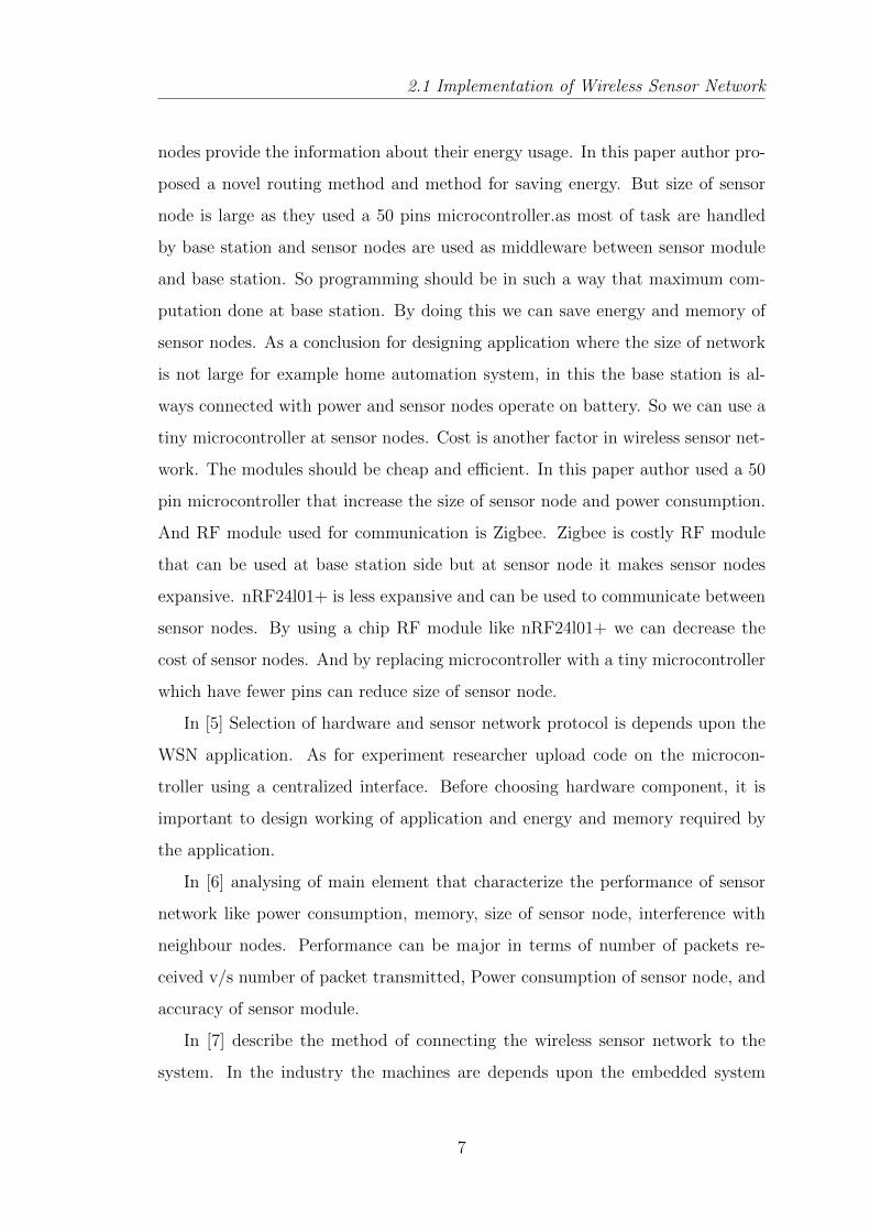
nodes provide the information about their energy usage. In this paper author pro-
posed a novel routing method and method for saving energy. But size of sensor
node is large as they used a 50 pins microcontroller.as most of task are handled
by base station and sensor nodes are used as middleware between sensor module
and base station. So programming should be in such a way that maximum com-
putation done at base station. By doing this we can save energy and memory of
sensor nodes. As a conclusion for designing application where the size of network
is not large for example home automation system, in this the base station is al-
ways connected with power and sensor nodes operate on battery. So we can use a
tiny microcontroller at sensor nodes. Cost is another factor in wireless sensor net-
work. The modules should be cheap and efficient. In this paper author used a 50
pin microcontroller that increase the size of sensor node and power consumption.
And RF module used for communication is Zigbee. Zigbee is costly RF module
that can be used at base station side but at sensor node it makes sensor nodes
expansive. nRF24l01+ is less expansive and can be used to communicate between
sensor nodes. By using a chip RF module like nRF24l01+ we can decrease the
cost of sensor nodes. And by replacing microcontroller with a tiny microcontroller
which have fewer pins can reduce size of sensor node.
In [5] Selection of hardware and sensor network protocol is depends upon the
WSN application. As for experiment researcher upload code on the microcon-
troller using a centralized interface. Before choosing hardware component, it is
important to design working of application and energy and memory required by
the application.
In [6] analysing of main element that characterize the performance of sensor
network like power consumption, memory, size of sensor node, interference with
neighbour nodes. Performance can be major in terms of number of packets re-
ceived v/s number of packet transmitted, Power consumption of sensor node, and
accuracy of sensor module.
In [7] describe the method of connecting the wireless sensor network to the
system. In the industry the machines are depends upon the embedded system
7
Page 17
2.2 Implementation of Intrusion Detection System
to operate. For example the temperature sensor detects the temperature into
the environment and sends a message to the machine or system to operate. The
functionality is designed by user on the machine or system.
2.2 Implementation of Intrusion Detection Sys-
tem
With the growth in wireless technology, the danger of attacks is also increase.
For making wireless technology secure cryptographic methods can be used. But
cryptographic methods can defence outside attacks. Intrusion detection system
monitors traffic of the sensor nodes and detect abnormal behaviour of the nodes.
The major approaches that an Intrusion Detection System can used to specify
attacks are [8]:
1. Anomaly Detection: this approach checks whether the behaviour of the
nodes can be consider normal or not. The approach first describes the fea-
ture of the normal node. After that any activity that is not describe into
the feature behaviour of node is consider as anomalous. Advantage of this
method is that it can detect novel attacks. And the disadvantage of this
method is false alarm rate is high.
2. Misuse Detection: this is rule-based method, rules are define on the basis
of the signature of known attacks. The behaviour of nodes is compare with
known attacks. and if behaviour match with predefined rules then attack
detected. this method work efficiently if the attack is known, but fails if the
attack is novel attack.
3. Specification-based Detection: this method is combination of anomaly de-
tection and misuse detection. This method focus on discovering deviation
from normal behaviours. In this mechanism the behaviour that can be con-
sider normal is defined manually by human. Drawback of this approach is
manually defining the all specification.
The major attacks that can be possible on a Wireless sensor network are [9]:
8
Page 18
2.2 Implementation of Intrusion Detection System
1. HELLO flood attacks: Wireless sensor network has broadcasting nature. To
discover neighbour nodes they broadcast HELLO packets. These packets can
be used to attack on a sensor node. Sensor nodes which receive these packets
assume that the packets are coming from authorized node and process them.
By this node energy is consume. This attack can be detected by bidirectional
verification.
2. Selective forward attacks: this attack can be possible in multi-path routing.
Sensor node assume that the intermediate node will forward the receive
packet to the base station. In this attack the intermediate node which is
malicious node forward packets but selective sensible packets are dropped
by the malicious node. Possible solution of this attack is by monitoring the
transmitted packets by neighbour nodes.
3. Wormhole attacks [10]: in this attack, an attacker record packet at one
place and tunnels it to another location. This attack can be done without
compromising any node. Because in this the attacker node offer less hop-
count to the base station. So the sensor node forwards the packet by the
attacker path.
4. Sybil attacks: the malicious node can pretend more than one node at a time.
By doing this attacker attract all the packets towards malicious node. The
malicious node can target the data aggregation, and routing mechanisms.
5. Denial of Service attacks: malicious activity by attacker that targets the sen-
sor nodes resources. The hardware of the sensor nodes are very constraints
and attacker tries to overload them.
Various IDS techniques are introduce to detect the attacks in WSNs [11] but most
of them can prevent from few of the WSN attacks. The most effective method
for detecting is clustering based approach. In which each node belong to a single
cluster and instead of transferring data to base station they transfer it to the
cluster head.
9
Page 19
2.3 Motivation
2.3 Motivation
Wireless sensor networks are group of hundreds to thousands of inexpensive
sensor nodes over an area for the monitoring certain phenomena. Designing and
programming these nodes is another challenging task as there are number of pa-
rameter effect nodes. These parameters are size, energy consumption, security of
data, memory of sensor node, communication power and data rate.
[4] With growth of wireless communications the application of Wireless sensor
networks (WSNs) is also come out. WSNs are generally used for wide area like
military use, forest-fire, parking system, tracking system, mines, healthcare, traffic
control application, nuclear plants, underwater, and industrial plants. These are
the applications in which sensors are deployed in remote area where an attacker
can easily harm wireless sensor network. Apart from that sensors are also used in
home applications which are also another challenging task. Provide user low cost,
long life and secure wireless sensor system is not that much easy as compared to
wired applications.
One of the wireless sensor networks applications is home security automation [5] .
In which sensor are deployed into the home to collect the information from envi-
ronment and send it to the user. A user interface application through which user
can control the WSN system. By these sensor nodes user is always updated with
the home environment. User can turn on or off any sensor by internet. But in
this case restrictions are more increases on wireless sensor networks like it should
be small enough so no one can identify it, must be secure from physical harm,
more accurate, reliable communication. Attacker can get the signal and break the
security system. So making more reliable wireless sensor network we required to
provide such a security which can identify the attacker and notify the user.
For data security cryptography is a solution [12] . But it can protect network from
outside attacks only. Intrusion detection system (IDS) can secure sensor network
from inside attacks. It monitors the traffic of the network and on the basis of rules
it filters the data packets.
The main research focus was to develop a sensor network which can provide home
10
Page 20
2.4 Objective
security from intruder and send a message when any intruder found. The IDS is
used to prevent the system from external attacker which increase the reliability of
the system.
2.4 Objective
Our objective is to designing and program sensor nodes that can provide home
security, light controlling and temperature control system [13]. The home au-
tomation system should be reliable, efficient (low false alarm rate) as sensors are
sensitive and can give you false alarm with a small variation in environment. And
most important it should not be expensive. Microcontroller used for designing
nodes is Attiny85 (8-pin microcontroller). Attiny85 is small in size and operate at
low power. Arduino board will be used as base station. Communication between
nodes will be established by using nRF24l01+ RF module. nRF24l01+ is low
cost transceiver. Each node will have a nRF24l01+ connected to microcontroller.
Microcontroller will be programmed in CPP language using Arduino sketch and
its library. Functionality of Wireless Sensor Network:
� Embedded sensor in the node will collect the information from the environ-
ment and forward it to base station using nRF24l01+.
� Communication between nRF24l01+ module and microcontroller will be
done by using SPI (Serial Peripheral Interface) interface. Its implemented
by using SPI both side.
� The board will have led to indicate the data transmit and received.
� Base station will connected to the computer through a USB port.
� Each sensor will have a 5v power battery.
� Each node will maintain a table of its neighbours which will be update within
a fixed time period.
� PIR motion sensor will send a message to base station whenever it detect
intruder in the house.
11
Page 21
2.4 Objective
� Light control system will control the light of the house. According to the
light intensity and human presence it will turn on/off the light.
� Light control system will control the light of the house. According to the
light intensity and human presence it will turn on/off the light.
� Temperature sensor will send a message to user whenever the temperature
of house is cross the certain threshold.
� Each node will be identify by its physical address (in the programming each
node is assigned with an physical address).
� An Intrusion detection system will be programmed on each microcontroller.
� IDS will send an alert message to base station whenever it found any mali-
cious activity into the network.
Zigbee module can be used as RF module but it is expensive and consume
more power as compare to nRF24l01+. For small wireless sensor networks the
RF module should be less expensive and energy efficient. and size of Zigbee is
bigger then the nRF24l0+ module. we can use nRF24l0+ with just 7 pins. but
Zigbee requires minimum 16 pins. so in case of Zigbee the microcontroller should
be atleast 16 pin and that increase the size of sensor node.
Our objective is to design a home security system which is cheap and energy
efficient. the nodes will be programmed and functioned as that if they found any
malicious activity into the network they will report to base staion.
12
Page 23
Chapter 3
Hardware Design
This section gives an insight into Wireless Sensor Networks and nRF24l01+. Hard-
ware design requires basic knowledge of hardware component and programming
knowledge. To program microcontroller, it is required to have programming knowl-
edge and some experience on hardware components.
3.1 Hardware Design Overview
Figure 4.1 represents the system in a simplified way:
Figure 3.1: Hardware Design Block Diagram
14
Page 24
3.1 Hardware Design Overview
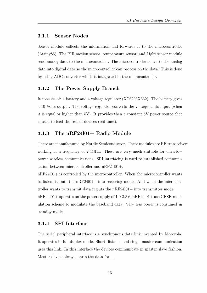
3.1.1 Sensor Nodes
Sensor module collects the information and forwards it to the microcontroller
(Attiny85). The PIR motion sensor, temperature sensor, and Light sensor module
send analog data to the microcontroller. The microcontroller converts the analog
data into digital data so the microcontroller can process on the data. This is done
by using ADC converter which is integrated in the microcontroller.
3.1.2 The Power Supply Branch
It consists of: a battery and a voltage regulator (XC6203X332). The battery gives
a 10 Volts output. The voltage regulator converts the voltage at its input (when
it is equal or higher than 5V). It provides then a constant 5V power source that
is used to feed the rest of devices (red lines).
3.1.3 The nRF24l01+ Radio Module
These are manufactured by Nordic Semiconductor. These modules are RF transceivers
working at a frequency of 2.4GHz. These are very much suitable for ultra-low
power wireless communications. SPI interfacing is used to established communi-
cation between microcontroller and nRF24l01+.
nRF24l01+ is controlled by the microcontroller. When the microcontroller wants
to listen, it puts the nRF24l01+ into receiving mode. And when the microcon-
troller wants to transmit data it puts the nRF24l01+ into transmitter mode.
nRF24l01+ operates on the power supply of 1.9-3.3V. nRF24l01+ use GFSK mod-
ulation scheme to modulate the baseband data. Very less power is consumed in
standby mode.
3.1.4 SPI Interface
The serial peripheral interface is a synchronous data link invented by Motorola.
It operates in full duplex mode. Short distance and single master communication
uses this link. In this interface the devices communicate in master slave fashion.
Master device always starts the data frame.
15
Page 25
3.2 Components
Although there can be multiple slaves and one master device but in this project
we are using only one mater and one slave configuration. SPI is also called a four
wire serial bus. SPI is also named as Synchronous Serial Interface often.
3.1.5 Arduino Programmer and USB Link
At the receiver side which is also the base station an Arduino Uno device is being
used. This also works as the programmer for the ATtiny85 microcontrollers. The
programming of microcontrollers is done with the help of ISP connections.
This module also has USB connectivity to PC. With the help of USB connection
the data received from nRF24l01+ can be sent to PC for display purpose. Also
we can send commands or data to microcontroller from PC. The USB connection
enables us to perform following tasks:
� A command word can be sent from PC to microcontroller. That command
word can either be meant for microcontroller or to nRF24l01+ module. If
command is for microcontroller it will be processed there or for the second
case it will be transferred to nRF24l01+ and will be processed there.
� Data from sensors can be received by PC and it will be used for display
purpose or controlling.
3.2 Components
This section of the thesis covers the basic description about each component which
is used to design the sensor nodes and base station as well. It also explains the
selection criteria if there was a possibility of choosing between different devices.
For each component a connection diagram is also given.
3.2.1 Microcontrollers
two microcontrollers of same family are used for the development of the sensor
nodes. Both microcontrollers are of 8-bit but have different pin counts and size. At
sensor nodes Attiny85 microcontroller is used and at base station side ATmega328
microcontroller is used.
16
Page 26
3.2 Components
1. ATtiny85 microcontroller
Power management:
� Very low power consumption.
� Active mode: 1MHz, 1.8V, 300A
� Power down Mode: 0.1 A @ 1.8 V
� A power reduction register gives a method to reduce power consump-
tion.
� Three different sleep modes: idle mode, ADC noise reduction mode,
power down mode.
� Idle mode: it enables microcontroller to wake up due to external inter-
rupts and internal interrupts as well.
� ADC noise reduction mode: it improves ADCs noise environment and
enables higher resolution for measurements.
� Power down mode: this mode stops all generated clocks and it will
allow only asynchronous module operations.
Universal serial Interface (USI) features:
� Synchronous data transfer via two wires.
� Synchronous data transfer via three wires.
� Interrupt on data reception.
� In two wire mode it can wake up from all sleep modes.
� It has start condition detector in two wire mode and with interrupt
detection.
Peripheral Features:
� Two PWM channels
� 8 bit timer/counter along with prescaler
� 8-bit high speed timer/counter with separate prescaler
17
Page 27
3.2 Components
� Output compare registers which are double buffered
� Phase correct pulse width modulator which is glitch free
� Three (TOV0, OCF0A, and OCF0B) independent interrupt source
� Auto reload on compare match (clear time)
� PWM period is variable.
� A programmable watchdog timer/counter with internal oscillator.
Figure 3.2: Start condition detector logic diagram
Connection Diagram
This connection is recommended in ATtiny85 datasheet. Also this is con-
nection for In-system-programming of microcontroller through ISP.
The remaining connections which includes the pins (I/O) and peripherals
are described in other sections of this thesis.
Figure 3.3: ATtiny85 connection diagram
18
Page 28
3.2 Components
2. Arduino Board with ATmega328 microcontroller
Arduino Uno board is based on ATmega328 microcontroller. It consists of
14 digital I/O pins out of which 6 can be used as PWM channels. It has 16
MHz ceramic oscillator, an ICSP header, a power jack, USB connection, and
a reset button. It has everything that is needed to support a microcontroller.
Its feature summary is given as following:
� Operating voltage is 5 V.
� DC current per I/O pin is 40mA.
� DC current for 3.3.V pin is 50mA.
� ATmega328 has 32KB of flash memory out of which
� .5KB will be used by boot loader.
� 2 KB of SRAM.
� 1KB of EEPROM.
� Recommended input voltage is 7-12V.
� USB Overcurrent protection for more than 500mA.
Figure 3.4: Arduino Uno SMD
19
Page 29
3.2 Components
3.2.2 The Nrf24L01+ Module
Introduction
It is a single 2.4GHz transceiver module. it have an integrated baseband pro-
tocol engine that is also called Enhanced Shockburst. It is suitable for very low
power wireless communication applications. The nrf24l01+ is designed to operate
in ISM frequency band of 2.4 2.4835GHz.
It is a 8-pin RF module which needs a microcontroller and few other passive com-
ponents to design wireless module. A serial peripheral interface (SPI) is needed
to configure and operate nrf24l01+. All configuration registers are contained by
a register map, which can be accessed with the SPI [14]. This register map is
accessible in all operating modes on nrf24l01+ chip.
The Enhanced Shockburst (Embedded Baseband Protocol Engine) relies upon
packet communication. It upkeeps various manual operating modes for advanced
autonomous protocol operations. An even flow of data between radio and micro-
controller is ensured by Internal FIFOs. The system cost is reduced by Enhanced
Shockburst because it handles all the operations that take place at high speed link
layer.
GFSK modulation is used by the transmitter and receiver front end. User config-
urable parameters such as air data rate, output power and frequency channels are
present there.nRF24l01+ supports air data rates of 2Mbps, 1Mbps and 250Kbps.
The two power saving modes combined with high air data rate make the nrf24l01+
to work with ultra-low power wireless communication applications.
A very good power supply rejection ratio (PSRR) is ensured by internal voltage
regulators. Hence it is having wide power supply range.
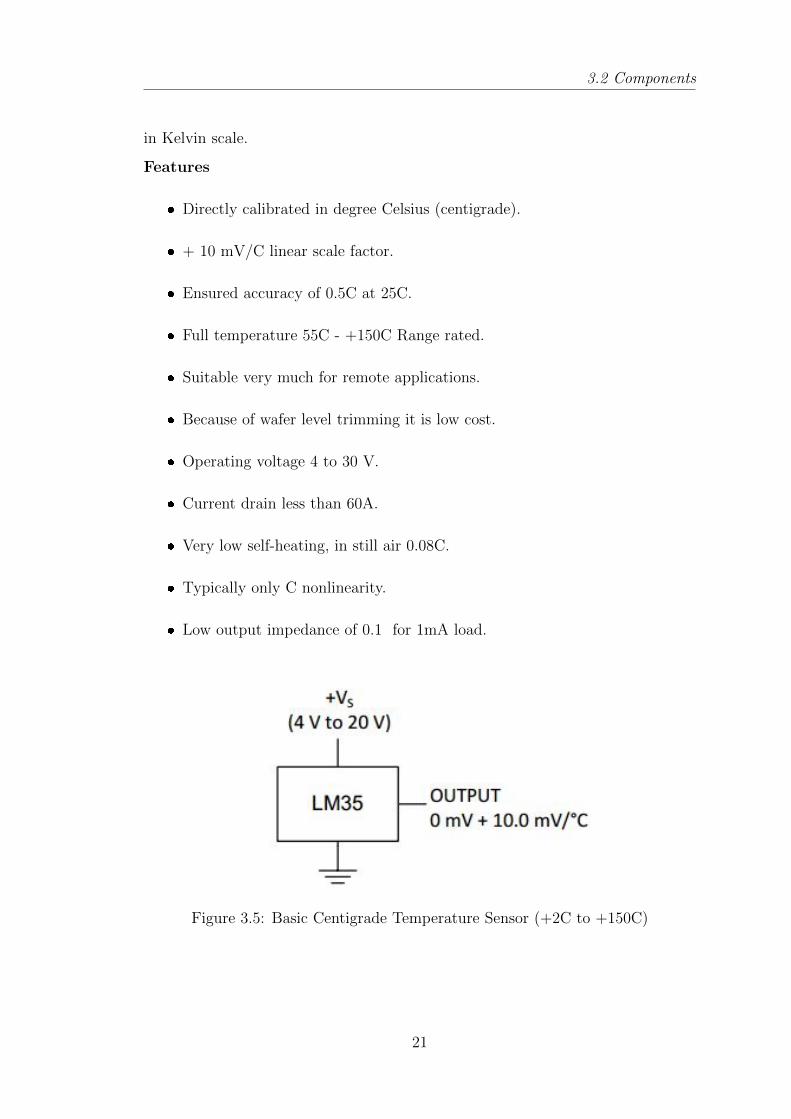
3.2.3 Temperature Sensor: LM35
LM35 series are integrated circuit precision temperature sensors. Its output volt-
age is in linear proportion to centigrade temperature scale. Hence to obtain scaling
in convenient centigrade, user does not need to subtract a big constant value from
the output. Thus these sensors have an advantage over linear sensors calibrated
20
Page 30
3.2 Components
in Kelvin scale.
Features
� Directly calibrated in degree Celsius (centigrade).
� + 10 mV/C linear scale factor.
� Ensured accuracy of 0.5C at 25C.
� Full temperature 55C - +150C Range rated.
� Suitable very much for remote applications.
� Because of wafer level trimming it is low cost.
� Operating voltage 4 to 30 V.
� Current drain less than 60A.
� Very low self-heating, in still air 0.08C.
� Typically only C nonlinearity.
� Low output impedance of 0.1 for 1mA load.
Figure 3.5: Basic Centigrade Temperature Sensor (+2C to +150C)
21
Page 31
3.2 Components
3.2.4 PIR Motion Sensor
PIR sensors [15]are used to sense motion. They are used to sense the human
presence in the sensor range. They dont wear out, low power, easy to use, small
and inexpensive. This is the reason they are mostly found in the applications
we use at homes or businesses. They are often called as IR motion sensors pyro
electric or passive infrared sensors.
Figure 3.6: Working of PIR
Feature
� Rectangular in size.
� Digital high pulse is 3V when motion is detected.
� Sensitivity range is 6 meters (20 feet), detection range is 110 x 70.
� Ideal power supply is 5 V. But work in range of 3-9V.
22
Page 32
3.2 Components
3.2.5 Light Dependent Resister (LDR)
Two photoconductive cells of cadmium sulphide (CdS) with same electrical [16]
responses as human eye forms a light dependent resistor. With the increase in
intensity of light the cell resistance decreases.
Feature
� Wider spectral response
� Having a low cost.
� Wide ambient temperature range.
23
Page 33
Construction and Working
Page 34
Chapter 4
Construction and Working
4.1 Construction of Hardware
When the hardware designing was finished the next stage was to turn up the de-
sign in real world.
The construction of hardware was not that much of a tough task because all the
raw material was available and one had to just mount all the components and
solder them. Three sensor nodes were constructed each controlled by attiny85
microcontrollers for communication nRF24l01+ module is solder with microcon-
troller.
Network topology is used by these node is Tree topology. In which the parent
node is base station. All three nodes are the child node of the base station. The
base station control them by using system. the leaf node transmit the data to
base station whenever they sense the environment.
The actual plan was to construct a receiver with ATmega32 just like sensor nodes
but later it was found out that one can use Arduino Uno as receiver which was
being used as programmer to program attiny85. Also now there was no need for
LCDs because of GUI of Arduino Uno.
The connection of nrf24l01+ with Arduino Uno will remain raw as we can not
solder them with the reusable ports. This will just increase the flexibility of the
project.
25
Page 35
4.2 Working
4.2 Working
The group of four sensor nodes are connected by using tree topology. The func-
tionality of the nodes are programmed to secure the room from intruder entry,
turn on/off light, and temperature parameter. Initially all nodes are in standby
mode, when base station trigger a node then only it activate.
4.2.1 Base station
Base station check whether the entered password is correct or not. The user
will have three attempt and if he failed all three time, then lock is blocked and
can be open by another secret key which is send to the user by telnet when the
all three attempt are finished. If the enter password is correct then the lock
will be unlocked and the PIR Motion sensor will be turn off as now user is into
the room so no need of motion detection. And light sensor will be turn on and
check whether the light intensity into the room is within the threshold or not.
while user enters password do
read password;
if entered password is correct then
Turnoff PIR sensor ;
Turnon Light sensor;
else
attempt++;
show(enter correct password);
if attemp ≥ 3 then
send alert message to use;
end
end
end
Algorithm 1: Base station
26
Page 36
4.2 Working
4.2.2 PIR Motion sensor
When the lock is locked, means no one is into the room that time the sensor is
in ON mode. In this case if any motion is detected then it send an message to
the base station and the base station will forward an alert message to the user
according to the frequency of motion. It will remain in ON condition until an
authorized user enters into the room. When an authorized user enters into the
room the PIR motion sensor goes into OFF mode.
4.2.3 Light sensor
When the lock is locked, means no one is into the room so that time light sensor
is in OFF mode. It will turn on when an authorized user enter into the room.
The light sensor sends the intensity of the light into the room to the base station.
And according to threshold the base station take decision.
27
Page 37
Software Development
Page 38
Chapter 5
Software Development
Arduino Firmware
With the help of Arduino sketches it was needed to program both ATtiny85 and
ATmega328 microcontrollers. Programming was done using ISP interface. The
sketches were needed to perform following tasks:
1. Drive ATtiny85 integrated USI to work as SPI.
2. Drive software SPI to communicate with nrf24 module.
3. Obtain samples of sensor data from A/D convertor.
4. Send the samples to nrf24 module so they can be transmitted.
5. Transfer received data from nrf24 to ATmega328 microcontroller.
6. Display the data at PC GUI.
All the programs have been written in Arduino 1.0.5-r2 in C/C++ language.
Program is then transferred to microcontroller flash using ISP connectors.
The program is divided into these parts:
1. Initialization and configuration of microcontroller integrated modules and
nrf24L01+. This stage basically consists of these steps:
� Pin configuration
� A/D convertor initialization
� SPI configuration
29
Page 39
5.2 SPI Configuration
� nRF24l0+ TX and RX configuration
2. The Main Loop: this part consists of the tasks that are repeated over and
over again
5.1 PIN Configuration
In this part of the program the write register will define the nature of the I/O pin
whether it is going to be input or output. The value of each digital buffer latch
is set or reset whenever it is necessary, if a output constant 1 or 0 is going to be
needed.
Some of the pins can stand different functions that mean they are remap able.
Software will assign these functions. It depends on the pin which is needed, pin
can be able to work as a digital I/O pin , an analog input pin, a reference clock
output, communication port line (SPI, ISP, ) or a PWM output. To provide these
features AVR family uses programmable multiplexers.
Figure 5.1: SPI read timings
5.2 SPI Configuration
It is data and control interface for nrf24. It gives access to nrf24s all features.
This interface contains six digital signals that are 5V tolerant.
� IRQ (Interrupt request)
� CE (chip enable is used to put chip in TX or RX mode).
� CSN (chip select not-SPI signal).
� SCK (Serial Clock- SPI signal).
30
Page 40
5.4 Intrusion Detection System
� MOSI (Master out Slave In - SPI signal).
� MISO (Master in Slave Out - SPI signal).
The SPI used in nrf24 is standard SPI with 10 Mbps of max data rate. To
start a new command there should be a high to low transition on CSN pin.
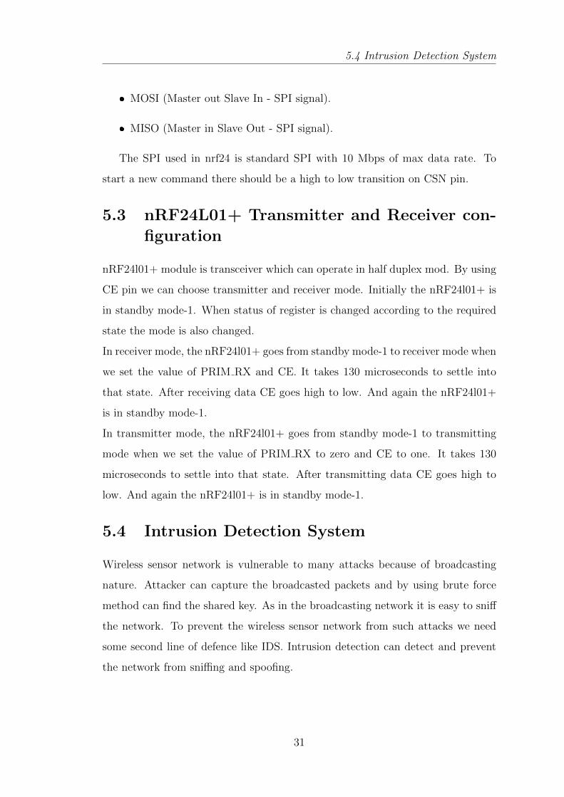
5.3 nRF24L01+ Transmitter and Receiver con-
figuration
nRF24l01+ module is transceiver which can operate in half duplex mod. By using
CE pin we can choose transmitter and receiver mode. Initially the nRF24l01+ is
in standby mode-1. When status of register is changed according to the required
state the mode is also changed.
In receiver mode, the nRF24l01+ goes from standby mode-1 to receiver mode when
we set the value of PRIM RX and CE. It takes 130 microseconds to settle into
that state. After receiving data CE goes high to low. And again the nRF24l01+
is in standby mode-1.
In transmitter mode, the nRF24l01+ goes from standby mode-1 to transmitting
mode when we set the value of PRIM RX to zero and CE to one. It takes 130
microseconds to settle into that state. After transmitting data CE goes high to
low. And again the nRF24l01+ is in standby mode-1.
5.4 Intrusion Detection System
Wireless sensor network is vulnerable to many attacks because of broadcasting
nature. Attacker can capture the broadcasted packets and by using brute force
method can find the shared key. As in the broadcasting network it is easy to sniff
the network. To prevent the wireless sensor network from such attacks we need
some second line of defence like IDS. Intrusion detection can detect and prevent
the network from sniffing and spoofing.
31
Page 41
5.4 Intrusion Detection System
5.4.1 Architecture
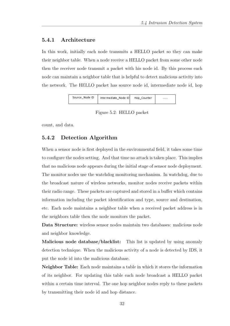
In this work, initially each node transmits a HELLO packet so they can make
their neighbor table. When a node receive a HELLO packet from some other node
then the receiver node transmit a packet with his node id. By this process each
node can maintain a neighbor table that is helpful to detect malicious activity into
the network. The HELLO packet has source node id, intermediate node id, hop
Figure 5.2: HELLO packet
count, and data.
5.4.2 Detection Algorithm
When a sensor node is first deployed in the environmental field, it takes some time
to configure the nodes setting. And that time no attack is taken place. This implies
that no malicious node appears during the initial stage of sensor node deployment.
The monitor nodes use the watchdog monitoring mechanism. In watchdog, due to
the broadcast nature of wireless networks, monitor nodes receive packets within
their radio range. These packets are captured and stored in a buffer which contains
information including the packet identification and type, source and destination,
etc. Each node maintains a neighbor table when a received packet address is in
the neighbors table then the node monitors the packet.
Data Structure: wireless sensor nodes maintain two databases: malicious node
and neighbor knowledge.
Malicious node database/blacklist: This list is updated by using anomaly
detection technique. When the malicious activity of a node is detected by IDS, it
put the node id into the malicious database.
Neighbor Table: Each node maintains a table in which it stores the information
of its neighbor. For updating this table each node broadcast a HELLO packet
within a certain time interval. The one hop neighbor nodes reply to these packets
by transmitting their node id and hop distance.
32
Page 42
5.4 Intrusion Detection System
while listening mode do
if Receive data then
check packets header ;
if ID == destination’s node ID then
drop packet;
else
receive packet;
end
if source and destinations ID is in neighbor table then
global detection();
else
drop packet;
end
end
end
Algorithm 2: Activating monitor node
33
Page 43
5.4 Intrusion Detection System
Pre-defined routing rules: Initially there is no entry in the malicious node
database, except for some predefined rules. IDS monitor the traffic on the basis
of following rule:
� Interval rule: each node transmits a packet within a fixed time interval. If
IDS found any anomaly then an alert message generated.
� Integrity rule: the payload of the packet must be same along the transmission
path.
� Delay rule: the delay between two transmissions if fixed, if the delay between
two node is more than defined then generate an alert message.
� Radio transmission range rule: each node received packets must be trans-
mitted by its own neighbor. It can be estimated by average receive power
(dBm).
The Intrusion Detection System has two modules:
1. Local detection: In this each node monitors their own node packet. The
traffic on the node is filter by using set of rules defined into the nodes
database. The set of rules are defined by the user and saved into the each
nodes database. The local detection() function is called when the packets
source id is in the receiver nodes blacklist then node Drop(packet).
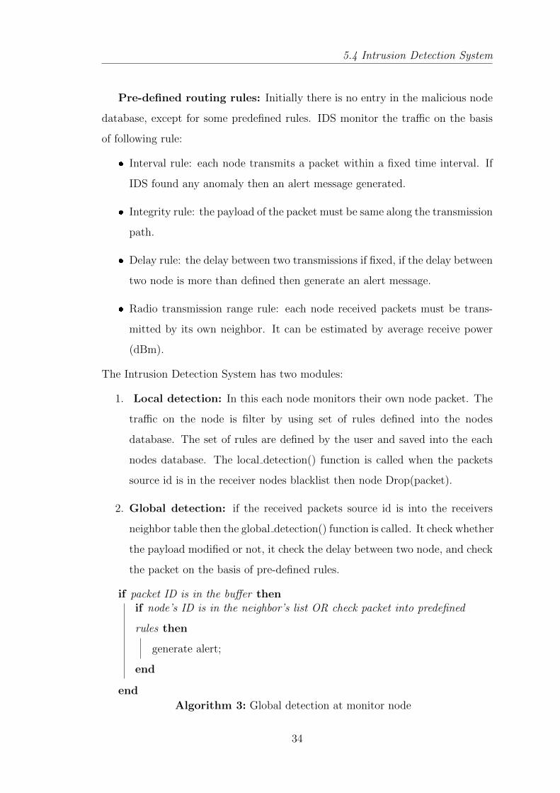
2. Global detection: if the received packets source id is into the receivers
neighbor table then the global detection() function is called. It check whether
the payload modified or not, it check the delay between two node, and check
the packet on the basis of pre-defined rules.
if packet ID is in the buffer thenif node’s ID is in the neighbor’s list OR check packet into predefined
rules then
generate alert;
end
end
Algorithm 3: Global detection at monitor node
34
Page 44
Implementation and Result
Page 45
Chapter 6
Implementation and Result
6.1 Implementation
In this work, the sensor nodes are used for home security and automatic light
controlling. The all three nodes are developed using Attiny85 microcontroller and
nRF24l01+ transceiver. A base station is developed using Arduino Uno board
which is connected to system using USB connection. For security of data, intrusion
detection system is deployed on each node. The IDS monitor the traffic into the
network and generate an alert message whenever malicious activity detected. The
all four node initially exchange their nodes ID and saved it into neighbour table.
By using local detection method node can monitor the packet which belongs to
receiver node. By using global detection method node can monitor data packet of
neighbour nodes. following are the pictures of all three sensor nodes
Figure 6.1: PIR Motion Sensor
36
Page 46
6.1 Implementation
PIR Motion Sensor: PIR module is connected to the microcontroller. when-
ver motion detected it sends some voltage value. and according to the voltage value
decision is taken by microcontroller
Temprature Sensor: Temprature sensor sense the temprature of the room and
Figure 6.2: Temprature Sensor
send the analog value to the base station. base station convert it into the digital
value.
Light Detection Sensor: It sense the intensity of light into the room and
Figure 6.3: Light Detection Sensor
sends voltage to base station. according to the intensity of the light into the room
microcontroller takes decision.
37
Page 47
6.2 Result
6.2 Result
Four nRF24l01+ node prototypes have been developed and they cover the basic
functionality. Each of them is capable of:
� Communicating over the air using the nRF24l01+ module.
� Monitoring its RF module power consumption.
� Sending stored data to other nodes by RF module.
� Receiving data from WSN nodes and processing on those packets.
� Forwarding HELLO packets to prepare neighbor table.
� By using neighbor table monitoring sensor nodes traffic.
� The sensor node can be turn on/off by base station.
All the four nodes are programmed with an intrusion detection system, which
is used to monitor traffic into the network. the local detection method provides
monitoring acket on the basis of predefined rules. the global detection method
used to monitor other nodes data.
38
Page 48
Conclusion and Future Work
Page 49
Chapter 7
Conclusion and Future Work
A group of sensor nodes are designed using nRF24l01+ RF module. Home security
prototype is developed by using PIR motion sensor, Light sensor and temperature
sensor. All these nodes are controlled by base station. The prototype consumption
power is less and cheaper than the existing work. nRF24l01+ can be used for small
network, as it doesnt support true mesh topology. intrusion detection system is
deployed on each node. IDS secure the sensor network from malicious traffic.the
false alarm rate is low.
In the future study, we expect that the our proposed work will be extended to
more number of nodes. furthermore for forwarding data packet suitable routing
protocol will be used.
40
Page 50
Bibliography
[1] A. Abduvaliyev, A.-S. K. Pathan, J. Zhou, R. Roman, and W.-C. Wong, “On
the vital areas of intrusion detection systems in wireless sensor networks,”
IEEE Communications Surveys & Tutorials, vol. 15, no. 3, pp. 1223–1237,
2013.
[2] H. Huang, S. Xiao, X. Meng, and Y. Xiong, “A remote home security system
based on wireless sensor network and gsm technology,” in Networks Security
Wireless Communications and Trusted Computing (NSWCTC), 2010 Second
International Conference on, vol. 1, pp. 535–538, IEEE, 2010.
[3] K. Romer and F. Mattern, “The design space of wireless sensor networks,”
Wireless Communications, IEEE, vol. 11, no. 6, pp. 54–61, 2004.
[4] D.-M. Han and J.-H. Lim, “Design and implementation of smart home en-
ergy management systems based on zigbee,” Consumer Electronics, IEEE
Transactions on, vol. 56, no. 3, pp. 1417–1425, 2010.
[5] P. E. Guerrero, I. Gurov, S. Santini, and A. Buchmann, “On the selection
of testbeds for the evaluation of sensor network protocols and applications,”
in Signal Processing Advances in Wireless Communications (SPAWC), 2013
IEEE 14th Workshop on, pp. 495–499, IEEE, 2013.
[6] G. Anastasi, A. Falchi, A. Passarella, M. Conti, and E. Gregori, “Performance
measurements of motes sensor networks,” in Proceedings of the 7th ACM
international symposium on Modeling, analysis and simulation of wireless
and mobile systems, pp. 174–181, ACM, 2004.
41
Page 51
Bibliography
[7] P. M. Scholl, B. E. Majoub, S. Santini, and K. Van Laerhoven, “Connecting
wireless sensor networks to the robot operating system,” Procedia Computer
Science, vol. 19, pp. 1121–1128, 2013.
[8] I. Krontiris, T. Dimitriou, T. Giannetsos, and M. Mpasoukos, “Intrusion
detection of sinkhole attacks in wireless sensor networks,” in Algorithmic
Aspects of Wireless Sensor Networks, pp. 150–161, Springer, 2008.
[9] I. Onat and A. Miri, “An intrusion detection system for wireless sensor
networks,” in Wireless And Mobile Computing, Networking And Commu-
nications, 2005.(WiMob’2005), IEEE International Conference on, vol. 3,
pp. 253–259, IEEE, 2005.
[10] S. Shin, T. Kwon, G.-Y. Jo, Y. Park, and H. Rhy, “An experimental study
of hierarchical intrusion detection for wireless industrial sensor networks,”
Industrial Informatics, IEEE Transactions on, vol. 6, no. 4, pp. 744–757,
2010.
[11] D. R. Raymond and S. F. Midkiff, “Denial-of-service in wireless sensor net-
works: Attacks and defenses,” Pervasive Computing, IEEE, vol. 7, no. 1,
pp. 74–81, 2008.
[12] R. Roman, J. Zhou, and J. Lopez, “Applying intrusion detection systems
to wireless sensor networks,” in Consumer Communications and Networking
Conference, vol. 1, pp. 640–644, 2006.
[13] J. A. Gutierrez, E. H. Callaway, and R. L. Barrett, Low-rate wireless per-
sonal area networks: enabling wireless sensors with IEEE 802.15. 4. IEEE
Standards Association, 2004.
[14] S. Marinkovic, C. Spagnol, and E. Popovici, “Energy-efficient tdma-based
mac protocol for wireless body area networks,” in Sensor Technologies and
Applications, 2009. SENSORCOMM’09. Third International Conference on,
pp. 604–609, IEEE, 2009.
42
Page 52
Bibliography
[15] H. Alemdar and C. Ersoy, “Wireless sensor networks for healthcare: A sur-
vey,” Computer Networks, vol. 54, no. 15, pp. 2688–2710, 2010.
[16] Y. Liu, Y. He, M. Li, J. Wang, K. Liu, and X. Li, “Does wireless sensor
network scale? a measurement study on greenorbs,” Parallel and Distributed
Systems, IEEE Transactions on, vol. 24, no. 10, pp. 1983–1993, 2013.
43