56
Edition: 28.03.12 Invacare ® Orion SERVICE MANUAL

Edition: 28.03.12
Invacare ® Orion SERVICE MANUAL
SERVICE MANUAL Invacare ® - Orion
2
These instructions contain information about:
Testing work
Repair Instructions
This manual is part of the instructions for use.
Service addresses
Invacare Austria GmbH
Herzog Odilostrasse 101
A-5310 Mondsee
Austria
(: +43 6232 5 53 50
Fax: +43 6232 5 53 54
WWW: www.invacare.at
Invacare n.v.
Autobaan 22
B-8210 Loppem (Brugge)
Belgium
(: +32 (0)50 83 10 10
Fax: +32 (0)50 83 10 11
WWW: www.invacare.be
Invacare AG
Benkenstraße 260
CH-4108 Witterswil
Switzerland
(: +41 (0)61487 70 80
Fax: +41 (0)61487 70 81
WWW: www.invacare.ch
Invacare Aquatec GmbH
Alemannenstraße 10
88316 Isny
Deutschland
( +49 (0)7562 70 00
Fax +49 (0)7562 7 00 66
WWW: www.invacare-aquatec.de
Invacare A/S
Sdr. Ringvej 37
DK-2605 Brøndby
Danmark
( (Kundeservice): +45 (0)36 90 00 00
Fax (Kundeservice): +45 (0)36 90 00 01
WWW: www.invacare.dk
Invacare® SA
c/ Areny s/n
Polígon Industrial de Celrà
E-17460 Celrà (Girona)
ESPAÑA
(: +34 (0)972 49 32 00
Fax: +34 (0)972 49 32 20
WWW: www.invacare.es
Invacare® Poirier SAS
Route de St Roch
F-37230 Fondettes
France
(: +33 (0)247 62 64 66
Fax: +33 (0)247 42 12 24
WWW: www.invacare.fr
Invacare ® - Orion SERVICE MANUAL
3
Invacare® Ltd
Pencoed Technology Park
Pencoed
Bridgend CF35 5HZ
United Kingdom
( (Customer services): +44 (0)1656 77 62 22
Fax (Customer services): +44 (0)1656 77 62 20
WWW: www.invacare.co.uk
Invacare Mecc San s.r.l.
Via dei Pini, 62
I - 36016 Thiene (VI)
Italia
(: +39 0445 38 00 59
Fax: +39 0445 38 00 34
WWW: www.invacare.it
Invacare Ireland Ltd.
Unit 5 Seatown Business Campus
Seatown Rd, Swords
County Dublin
Ireland
(: +353 18 10 70 84
Fax: +353 18 10 70 85
WWW: www.invacare.ie
Invacare® AS
Grensesvingen 9
Postboks 6230
Etterstad
N-0603 Oslo
Norge
( (Kundeservice): +47 (0)22 57 95 00
Fax (Kundeservice): +47 (0)22 57 95 01
WWW: www.invacare.no
Invacare® B.V.
Celsiusstraat 46
NL-6716 BZ Ede
Nederland
(: +31 (0)318 69 57 57
Fax: +31 (0)318 69 57 58
WWW: www.invacare.nl
Invacare Lda
Rua Estrada Velha, 949
P-4465-784 Leça do Balio
Portugal
(: +351 225 10 59 46
(: +351 225 10 59 47
Fax: +351 225 10 57 39
WWW: www.invacare.pt

SERVICE MANUAL Invacare ® - Orion
4
Återförsäljare:
Invacare® AB
Fagerstagatan 9
S-163 91 Spånga
Sverige
Tillverkare:
Invacare® Deutschland GmbH
Kleiststraße 49
D-32457 Porta Westfalica
Deutschland
( (Kundtjänst): +46 (0)8 761 70 90
Fax (Kundtjänst): +46 (0)8 761 81 08
WWW: www.invacare.se
MÖLNDAL
(┐ +46 (0)31 86 36 00
Fax: +46 (0)31 86 36 06
LANDSKRONA
(: +46 (0)418 2 85 40
Fax: +46 (0)418 1 80 89
OSKARSHAMN
(: +46 (0)491 1 01 40
Fax: +46 (0)491 1 01 80
Eastern european countries
European Distributor Organisation (EDO)
Kleiststraße 49
D-32457 Porta Westfalica
Deutschland
( +49 (0)5731 75 45 40
Fax +49 (0)5731 75 45 41
WWW: www.invacare.de

Invacare ® - Orion SERVICE MANUAL
5
Table of Contents
Chapter Page
1 INTRODUCTION 7
1.1 General information 7
1.2 Notes on transport 7
1.3 Definition and representation of information and safety information in this manual 8
1.4 Hazard symbols and symbols used 9
1.5 Images in this manual 10
2 SAFETY AND FITTING INSTRUCTIONS 11
2.1 Before any inspection or repair work 11
2.2 Personal safety equipment 11
2.3 General safety information and information about fitting / removal 11
3 TIGHTENING TORQUES 13
4 OVERVIEW ELECTRONIC MODULES 14
5 SERVICE PLAN (1X ANNUALLY) 15
6 OPERATIONAL FAULTS 17
6.1 Operational faults 17 6.1.1 Drive fault diagnosis 17
6.2 Error Codes and Diagnostic Codes 18
7 REPAIR WORK 20
7.1 General warning information on installation work 20
7.2 Replacing the drive motor 20
7.3 Replacing wheel suspension 23
7.4 Replacing shock absorber 25
7.5 Replacing front axle 27
7.6 Replacing steering column/fork 3-wheel 28
SERVICE MANUAL Invacare ® - Orion
6
7.7 Replacing brakes 31
7.8 Replacing brake cable 33
7.9 Replacing steering linkage/steering rod 34
7.10 Replacing the seat suspension / spring 36
7.11 Replacing operating console 38
7.12 Replacing bend speed reducer 40
7.13 Replacing the potentiometer 42
7.14 Replacing front headlight (lamp) 44
7.15 Replacing the front direction indicators 46
7.16 Replacing centre brake light 47
7.17 Replacing rear lights/direction indicators 49
7.18 Replacing the electronic module 51
7.19 Updating software 54
Invacare ® - Orion SERVICE MANUAL
7
1 Introduction
1.1 General information
· Service and maintenance work must be carried out taking this service manual into account.
· It is imperative that you observe safety information.
· Information about operation or about general maintenance and care work on the mobility aid should be taken from the operating manual.
· You can find information about ordering spare parts in the spare parts catalogue.
· Only use original Invacare® spare parts. The guarantee will become invalid if other spare parts are used!
· We reserve the right to make any alterations on the grounds of technical improvements.
· The mobility aid may only be maintained and overhauled by qualified personnel.
· The minimum requirement for service technicians is suitable training, such as in the cycle or orthopaedic mechanics fields, or sufficiently long-term job experience. - Experience in the use of electrical measuring equipment (multimeters) is also a requirement. - Special Invacare® training is recommended.
· Alterations to the mobility aid which occur as a result of incorrectly or improperly executed maintenance or overhaul work lead to the exclusion of all liability on the side of INVACARE.
· If you have any problems or questions please contact Invacare® Service.
1.2 Notes on transport
· If the mobility aid has to be shipped back to the manufacturer for major repairs, you should always use the original packaging for transport.
· Please attach a precise description of the fault.

SERVICE MANUAL Invacare ® - Orion
8
1.3 Definition and representation of information and safety information in this manual Different types of information and signal words are used throughout this manual.
HAZARD!
The signal word "HAZARD!" refers to immediate hazards. · The following lines in italics refer to actions which serve to avoid such hazards.
WARNING!
The signal word "WARNING!" refers to possibly-occurring hazards which can lead to death or serious injuries if they are not avoided. · The following lines in italics refer to actions which serve to avoid such hazards.
ATTENTION!
The signal word "ATTENTION!" refers to possibly-occurring hazards which can lead to minor injuries and/or material damage if they are not avoided. · The following lines in italics refer to actions which serve to avoid such hazards.
CAUTION!
The signal word "CAUTION!" refers to hazards which could lead to material damage if they are not avoided. · The following lines in italics refer to actions which serve to avoid such hazards.
Note
The signal word "Note" is used to denote general information which simplifies the handling of your product and refers to special functions.

Invacare ® - Orion SERVICE MANUAL
9
1.4 Hazard symbols and symbols used Different types of hazard symbols and symbols are used throughout this manual.
General hazards
This symbol warns you of general hazards! · Always follow the instructions to avoid injury to the user or damage to the product!
BURN HAZARD!
This symbol warns you of the danger of chemical burns, for example due to the discharge of battery acids! · Always follow the instructions to avoid injury to the user or damage to the product!
DANGER OF CRUSHING!
This symbol warns you of crushing hazards due to inattentive working with heavy components. · Always follow the instructions to avoid injury to the user or damage to the product!
EXPLOSION HAZARD!
This symbol warns you of an explosion hazard, which can be caused by excessive tyre pressure in a pneumatic tyre. · Always follow the instructions to avoid injury to the user or damage to the product!
Wear safety shoes
The symbol refers to the requirement for wearing safety shoes. · Wear standardised safety shoes during all work.
Wear eye protection
This symbol refers to the requirement for wearing eye protection, for example when working with batteries. · Wear eye protection when this symbol is shown.
Wear safety gloves
This symbol refers to the requirement for wearing safety gloves, for example when working with batteries. · Wear safety gloves when this symbol is shown.
Note
This symbol identifies general information which is intended to simplify working with your product and which refers to special functions.
Requirements:
· This symbol identifies a list of various tools, components and items which you will need in order to carry out certain work. Please do not attempt to carry out the work if you do not have the listed tools available.
Always dispose used or damaged batteries correctly The symbol refers to information for the correct disposal of used or damaged batteries.

SERVICE MANUAL Invacare ® - Orion
10
1.5 Images in this manual The detailed images in this manual are given digits to identify various components. Component numbers in text and operational instructions always relate to the image directly above.

Invacare ® - Orion SERVICE MANUAL
11
2 Safety and fitting instructions These safety instructions are intended to prevent accidents at work, and it is imperative that they are observed.
2.1 Before any inspection or repair work
· Read and observe this repair manual and the associated operating manual!
· Observe the minimum requirements for carrying out the work (see chapter entitled „General information)!
2.2 Personal safety equipment
Safety shoes
The mobility device, and some of its components, are very heavy. These parts can result in injuries to the feet if they are allowed to drop. · Wear standardised safety shoes during all work.
Eye protection
It is possible that battery acid can be discharged when working on defective batteries or when handling batteries improperly. · Always wear eye protection when working on any defective or possibly defective batteries.
Safety gloves
It is possible that battery acid can be discharged when working on defective batteries or when handling batteries improperly. · Always wear acid-proof safety gloves when working on any defective or possibly defective
batteries.
2.3 General safety information and information about fitting / removal
WARNING: Danger of crushing!
Various components such as the drive unit, batteries, seat etc are very heavy. This results in injury hazards to your hands! · Please note the high weight of some components! This applies especially to the removal of
drive units, batteries and the seat.
WARNING!
Injury hazard if the vehicle starts moving unintentionally during repair work! · Switch the power supply off (ON/OFF key)! · Engage the drive! · Before raising the vehicle, secure the wheels by blocking them with wedges!
ATTENTION!
Fire and burn hazard due to electrical short-circuit! · The mobility device must be completely switched off before removal of voltage-carrying
components! To do this, remove the batteries. · Avoid short-circuiting the contacts when carrying out measurements on voltage-carrying
components!

SERVICE MANUAL Invacare ® - Orion
12
CAUTION!
Danger of burns from hot surfaces on the motor! · Allow the motors to cool down before commencing work on them.
ATTENTION!
Injury hazard and danger of damage to vehicle due to improper or incomplete maintenance work! · Use only undamaged tools in good condition. · Some moving parts are mounted in sockets with PTFE coating (Teflon™). Never grease
these sockets! · Never use "normal" nuts instead of self-locking nuts. · Always use correctly-dimensioned washers and spacers · When reassembling, always replace any cable ties which were cut during dismantling. · After completing your work / before renewed start-up of the mobility device, check all
connections for tight fitting. · After completing your work / before renewed start-up of the mobility device, check all parts for
correct locking. · Only operate the vehicle with the approved tyre pressures (see technical data). · Check all electrical components for correct function. Please note that incorrect polarity can
result in damage to the electronic. · Always carry out a trial run at the end of your work.
Note
Mark all current settings for the mobility aid (seat, armrests, backrest etc.), and the associated cable connecting plugs, before dismantling. This makes reassembly easier. All plugs are fitted with mechanical safety devices which prevent release of the connecting plugs during operation. To release the connecting plugs the safety devices must be pressed in. When reassembling ensure that these safety devices are correctly engaged.
WARNING!
Any changes to the drive program can affect the driving characteristics and the tipping stability of the vehicle! · Changes to the drive program may only be carried out by trained Invacare® specialist
dealers! · Invacare® supplies all mobility aids with a standard drive program ex-works. Invacare® can
only give a warranty for safe vehicle driving behaviour - especially tipping stability - for this standard drive program!
Invacare ® - Orion SERVICE MANUAL
13
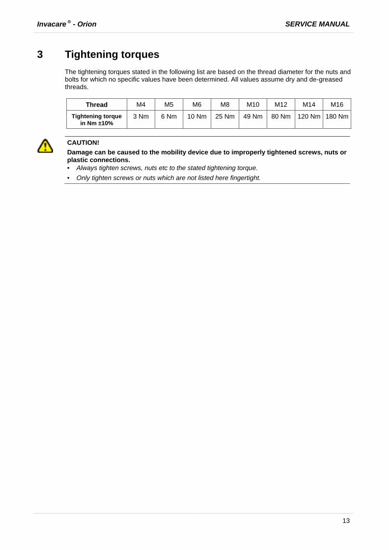
3 Tightening torques The tightening torques stated in the following list are based on the thread diameter for the nuts and bolts for which no specific values have been determined. All values assume dry and de-greased threads.
Thread M4 M5 M6 M8 M10 M12 M14 M16
Tightening torque in Nm ±10%
3 Nm 6 Nm 10 Nm 25 Nm 49 Nm 80 Nm 120 Nm 180 Nm
CAUTION!
Damage can be caused to the mobility device due to improperly tightened screws, nuts or plastic connections. · Always tighten screws, nuts etc to the stated tightening torque. · Only tighten screws or nuts which are not listed here fingertight.

SERVICE MANUAL Invacare ® - Orion
14
4 Overview electronic modules Different electronic modules can be installed in the scooter. These are listed below:
Electronic modules Designation Notes
Rhino1 DS72KB01 DS112KB02
max. current: 70 A 110 A
Rhino2 DS90 DS120
max. current: 90 A 120 A

Invacare ® - Orion SERVICE MANUAL
15
5 Service plan (1x annually)
Component Check Remedy Notes ü Seat: · Welded seams,
fixings and upholstery
· Tighten screws, replace parts if damaged
· Seat suspension · Grease the spring generously, replace parts if damaged
See "Replacing the seat suspension / spring" on page 36
Frames (chassis) / battery mounting
· Check fixings, welded seams and battery mounting
· Check battery fixing straps
· Tighten screws, replace parts if damaged
Wheel suspension and wheels
· Check drive wheels for tight fit
· Tighten hub nuts, replace if necessary
· Check steering wheels for tight fit, float and side play
· Adjust / replace
· Pneumatic tyre · Repair or replace if damaged
See operating manual
· Check tracking and steering linkage.
· Tighten screws · Check tracking
and steering
Brake · Test brake function in pushing mode
· Adjust or replace brake
Shock absorber · Check shock absorber
· Adjust or replace shock absorber
Drive units, coupling mechanism
· Check functions in drive and push modes
· Check clutch mechanism
· Replace motor if necessary
· Tighten screws / nuts, adjust or replace
Lighting · Check function · Check cable/plug
connections
· Replace lightbulbs or cable
Batteries · Check batteries for damage
· Replace batteries See operating manual
· Check battery voltage
· charge batteries See operating manual
· Check contacts and terminals
· Clean contacts and terminals

SERVICE MANUAL Invacare ® - Orion
16
Component Check Remedy Notes ü Drive electronic · Status display
flashing · Fixing · Cable, connecting
plug · Drive lever function · Power supply
· Evaluate blinking code
· Tighten or replace fixing.
· Replace cable, connecting plug.
· Replace drive lever
· Replace cable, connecting plug or console
Drive program · Check drive electronic program version Newer version available?
· Update software
Speed reduction in bends
· Check cable and connecting plug
· Check function
· Adjust or replace sensor on microswitch.

Invacare ® - Orion SERVICE MANUAL
17
6 Operational Faults
6.1 Operational faults Please proceed as follows if you have any problems:
· First assess the possible cause of the problem using the following table. · Check the drive console status display. Evaluate the blink error code. · Carry out the necessary checks and repairs as recommended in the following table.
6.1.1 Drive fault diagnosis
PROBLEM OTHER SYMPTOMS
POSSIBLE CAUSE
SOLUTION Documentation
Scooter will not start
Status display on operating console does not illuminate
Batteries possibly defective
· Replace batteries
See operating manual
Batteries possibly over-discharged
· Pre-charge batteries
See operating manual
Power supply to operating console possibly interrupted
· Check master fuse
See operating instructions for main fuse position
· Check cable between modules for loose connections or damage
See "Replacing the electronic module" on page 51
Operating console possibly defective
· Replace operating console
See "Replacing operating console" on page 38
Operating unit status display blinking
Various causes · Assess error code
See "Error Codes and Diagnostic Codes" on page 18
SERVICE MANUAL Invacare ® - Orion
18
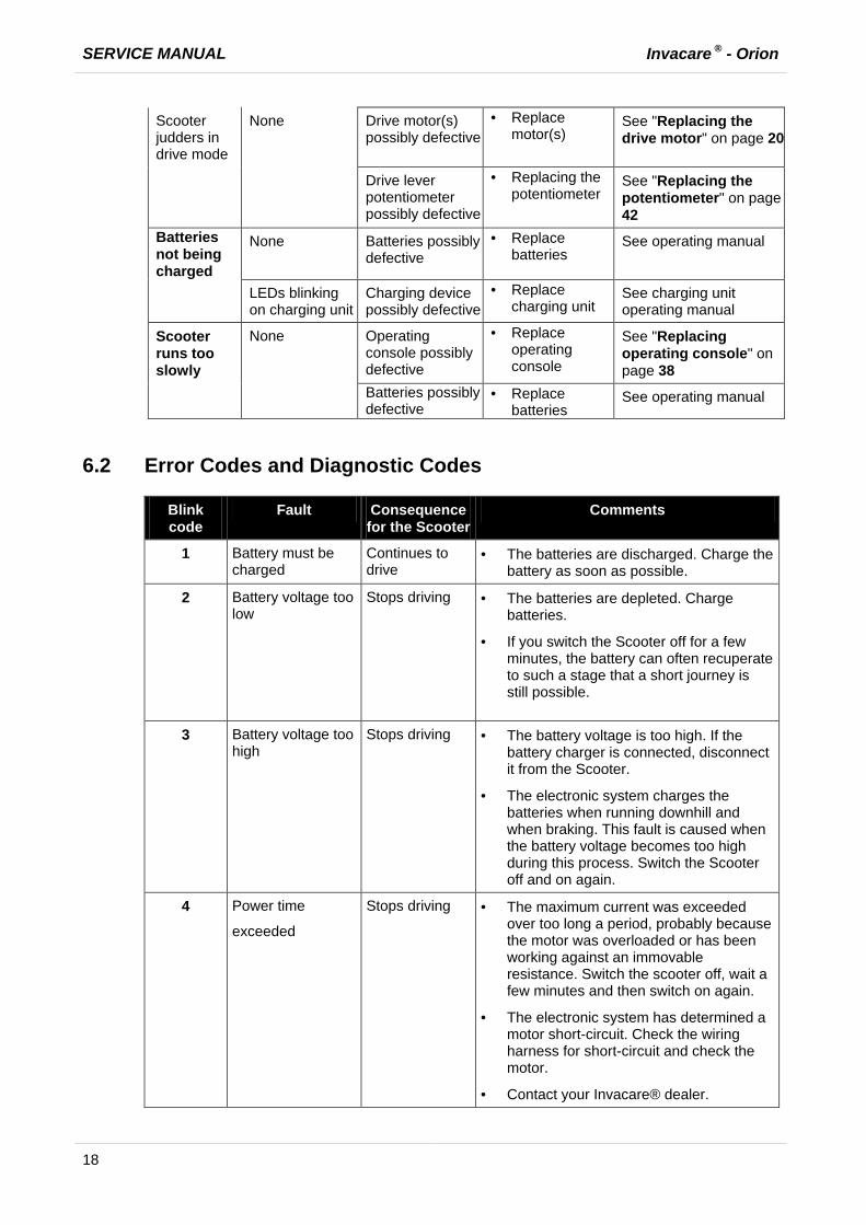
Scooter judders in drive mode
None Drive motor(s) possibly defective
· Replace motor(s)
See "Replacing the drive motor" on page 20
Drive lever potentiometer possibly defective
· Replacing the potentiometer
See "Replacing the potentiometer" on page 42
Batteries not being charged
None Batteries possibly defective
· Replace batteries
See operating manual
LEDs blinking on charging unit
Charging device possibly defective
· Replace charging unit
See charging unit operating manual
Scooter runs too slowly
None Operating console possibly defective
· Replace operating console
See "Replacing operating console" on page 38
Batteries possibly defective
· Replace batteries
See operating manual
6.2 Error Codes and Diagnostic Codes
Blink code
Fault Consequence for the Scooter
Comments
1 Battery must be charged
Continues to drive
· The batteries are discharged. Charge the battery as soon as possible.
2 Battery voltage too low
Stops driving · The batteries are depleted. Charge batteries.
· If you switch the Scooter off for a few minutes, the battery can often recuperate to such a stage that a short journey is still possible.
3 Battery voltage too high
Stops driving · The battery voltage is too high. If the battery charger is connected, disconnect it from the Scooter.
· The electronic system charges the batteries when running downhill and when braking. This fault is caused when the battery voltage becomes too high during this process. Switch the Scooter off and on again.
4 Power time
exceeded
Stops driving · The maximum current was exceeded over too long a period, probably because the motor was overloaded or has been working against an immovable resistance. Switch the scooter off, wait a few minutes and then switch on again.
· The electronic system has determined a motor short-circuit. Check the wiring harness for short-circuit and check the motor.
· Contact your Invacare® dealer.

Invacare ® - Orion SERVICE MANUAL
19
Blink code
Fault Consequence for the Scooter
Comments
5 Brake failure Stops driving · Ensure that the disconnection lever is pressed in.
· There is a defect in the braking coil or in the cabling. Check the magnetic brake and cabling for open or short-circuited circuitry. Contact your Invacare® dealer.
6 No neutral position when switching Scooter on.
Stops driving · Drive lever is not in neutral when the keyswitch was turned. Put the drive lever in neutral, turn the power off and then turn on again.
· It may be necessary to recalibrate the drive lever. Contact your Invacare® dealer.
7 Fault in speed potentiometer
Stops driving · The drive lever electronic could be faulty or incorrectly connected. Check the cabling for open or short-circuited circuitry.
· Potentiometer is not correctly adjusted. Put the potentiometer into the centre position.
8 Motor voltage error Stops driving · The motor or its cabling is defective Check the cabling for open or short-circuited circuitry.
9 Miscellaneous internal fault
Stops driving · Contact your Invacare® dealer.
10 Push/freewheel mode error
Stops driving · The Scooter has exceeded the permissible maximum speed during pushing or freewheeling. Switch the electronic system off and on again.

SERVICE MANUAL Invacare ® - Orion
20
7 Repair Work
7.1 General warning information on installation work
CAUTION!
Risk of damage to the vehicle! Collisions can be caused if shim rings are removed from the drive wheels during installation work! Shim rings are frequently placed between the drive shaft and the wheel hub to compensate tolerances. Collisions can be caused if these shim rings are removed and not re-installed! · Install all shim rings in exactly the same positions they were in before dismantling.
7.2 Replacing the drive motor
ATTENTION! Risk of accident.
When parking the scooter on the scooters support wheels it is no longer slowed by the engine brake. The scooter can roll away out of control. · Place the scooter rear frame on a supporting wooden block before you remove the wheels.
ATTENTION! Risk of accident.
Accidental rolling can lead to accidents. · Secure the scooter against rolling away.
Note:
When disassembling, note the position of small parts such as screws and washers. Put small parts down so that they can be reassembled in the right sequence.
Note:
The plugs on the electronic module cannot be wrongly connected because all plugs have a different size and only fit in one socket.
Requirements:
· Open spanner, 10 mm. · Open spanner, 17 mm. · oblique pliers · Rubber hammer · Phillips screwdriver · Supporting wooden block

Invacare ® - Orion SERVICE MANUAL
21
· Secure the scooter against rolling away.
· Place supporting wooden block under the frames at battery holder height.
· Remove the seat.
· Remove motor cover.
· Disconnect both battery plugs (1).
· From the operating manual:
· Unscrew the rear wheel fixing bolts.
· Remove rear wheels.
· Disconnect plugs from electronic module.
Rhino1: DS72KB01
DS112KB02
Rhino 2: DS90:
DS120:

SERVICE MANUAL Invacare ® - Orion
22
· Remove both screws (2) from the wheel cover (1).
· Remove wheel cover (1).
· Remove both screws (1) from the drive holder (2).
· Remove drive holder (2).
· Remove screws (1) on disengaging lever (2).
· Remove disengaging lever (2).
· Lifted drive out of its holder and take it out of the frames to the side.
· Replace drive unit.
· Reassembly of the drive takes place in reverse order
· Check all functions (trial run).
Invacare ® - Orion SERVICE MANUAL
23
7.3 Replacing wheel suspension
ATTENTION! Risk of accident.
Accidental rolling can lead to accidents. · Secure the scooter against rolling away.
Note:
When disassembling, note the position of small parts such as screws and washers. Put small parts down so that they can be reassembled in the right sequence.
Requirements:
· Open spanner, 10 mm. · Open spanner, 12 mm. · Open spanner, 13 mm. · Open spanner, 32 mm. · Phillips screwdriver · Supporting wooden block
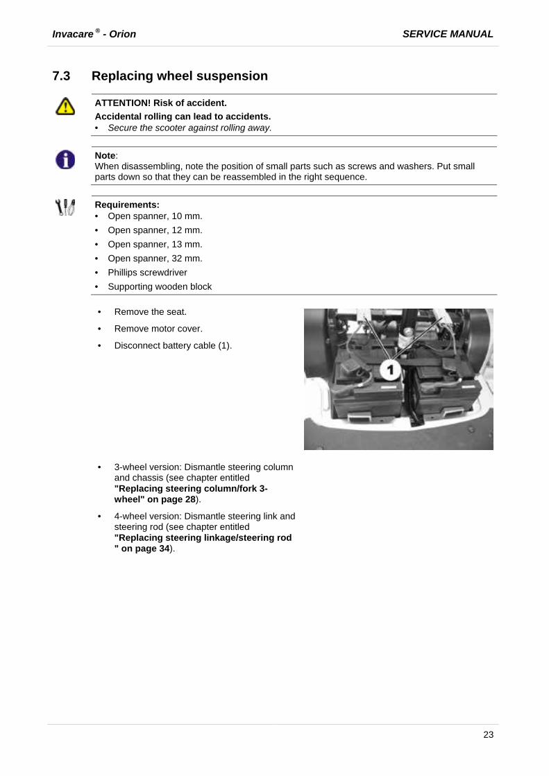
· Remove the seat.
· Remove motor cover.
· Disconnect battery cable (1).
· 3-wheel version: Dismantle steering column and chassis (see chapter entitled "Replacing steering column/fork 3-wheel" on page 28).
· 4-wheel version: Dismantle steering link and steering rod (see chapter entitled "Replacing steering linkage/steering rod " on page 34).

SERVICE MANUAL Invacare ® - Orion
24
· Loosen wheel suspension screw (1).
· Loosen knurled screw (2).
· Replace wheel suspension
· Reassembly takes place in the reverse order.
· Adjust tracking (see chapter entitled "Replacing steering linkage/steering rod " on page 34).
· Check function (trial run).
Invacare ® - Orion SERVICE MANUAL
25
7.4 Replacing shock absorber
ATTENTION! Risk of accident.
When parking the scooter on the scooters support wheels it is no longer slowed by the engine brake. The scooter can roll away out of control. · Place the scooter rear frame on a supporting wooden block before you remove the wheels.
ATTENTION! Risk of accident.
Accidental rolling can lead to accidents. · Secure the scooter against rolling away.
Note:
When disassembling, note the position of small parts such as screws and washers. Put small parts down so that they can be reassembled in the right sequence.
Note:
The drive motor needs to be removed before you can replace the left-hand shock absorber. If the right-hand shock absorber is to be replaced, you do not need to remove the drive motor.
Requirements:
· Open spanner, 10 mm. · Open spanner, 17 mm. · oblique pliers · Rubber hammer · Phillips screwdriver · 2 Allen keys 5m · Supporting wooden block
Left-hand shock absorber
· Remove drive motor (see chapter entitled "Replacing the drive motor" on page 20)
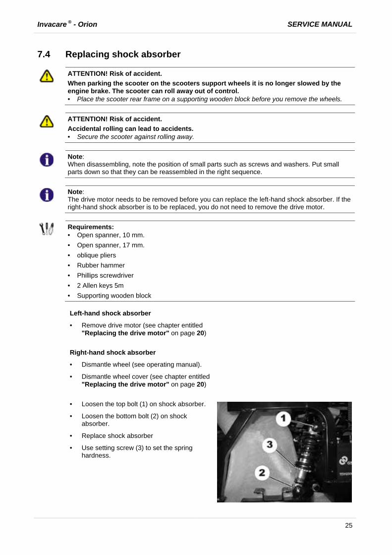
Right-hand shock absorber
· Dismantle wheel (see operating manual).
· Dismantle wheel cover (see chapter entitled "Replacing the drive motor" on page 20)
· Loosen the top bolt (1) on shock absorber.
· Loosen the bottom bolt (2) on shock absorber.
· Replace shock absorber
· Use setting screw (3) to set the spring hardness.

SERVICE MANUAL Invacare ® - Orion
26
· Reassembly of the shock absorber takes
place in reverse order.
· Check function (trial run).
Invacare ® - Orion SERVICE MANUAL
27
7.5 Replacing front axle
ATTENTION! Risk of accident.
Accidental rolling can lead to accidents. · Secure the scooter against rolling away.
Note:
When disassembling, note the position of small parts such as screws and washers. Put small parts down so that they can be reassembled in the right sequence.
Note:
The front axle can only be replaced on the 3-wheel version. The 4-wheel version does not have a replaceable axle.
Requirements:
· Open spanner, 17 mm. · Open spanner, 19 mm. · Supporting wooden block
· Remove the seat.
· Remove motor cover.
· Separate battery cable.
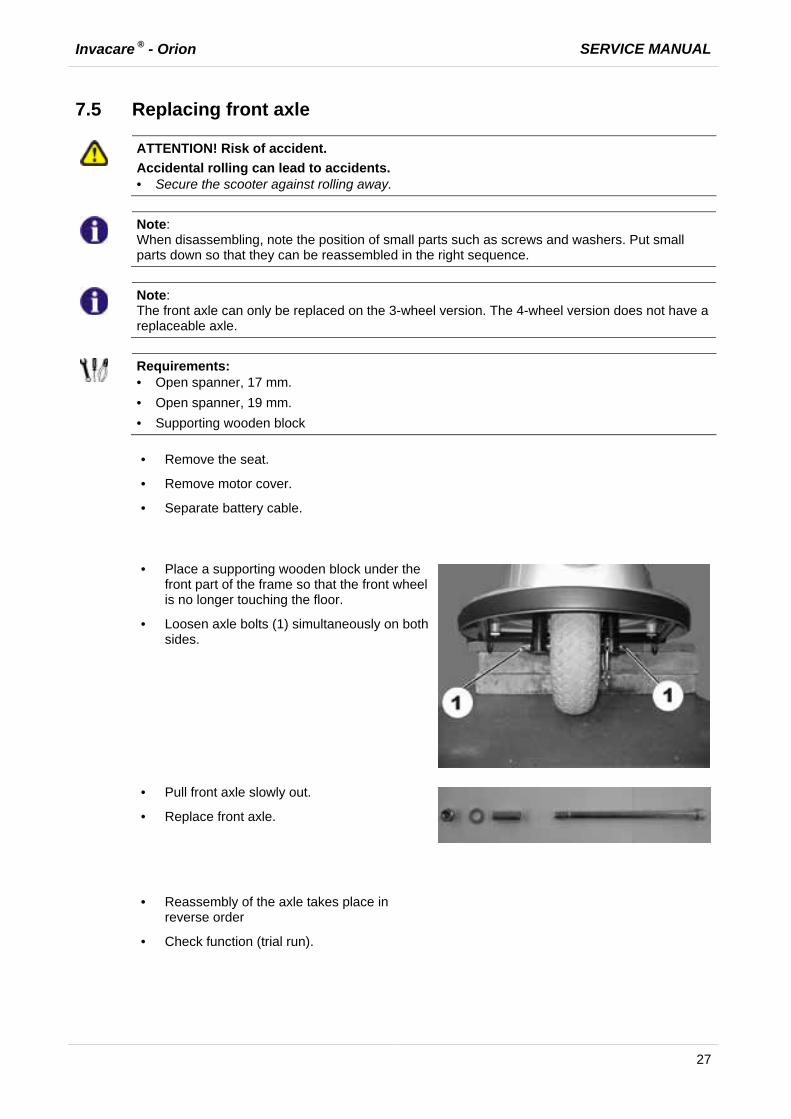
· Place a supporting wooden block under the
front part of the frame so that the front wheel is no longer touching the floor.
· Loosen axle bolts (1) simultaneously on both sides.
· Pull front axle slowly out.
· Replace front axle.
· Reassembly of the axle takes place in
reverse order
· Check function (trial run).
SERVICE MANUAL Invacare ® - Orion
28
7.6 Replacing steering column/fork 3-wheel
ATTENTION! Risk of accident.
Accidental rolling can lead to accidents. · Secure the scooter against rolling away.
Note:
When disassembling, note the position of small parts such as screws and washers. Put small parts down so that they can be reassembled in the right sequence.
Requirements:
· Open spanner, 10 mm. · Open spanner, 17 mm. · Open spanner, 19 mm. · Open spanner, 32 mm. · Phillips screwdriver · Supporting wooden block
· Remove the seat.
· Remove motor cover.
· Disconnect battery cable (1).
· Place a supporting wooden block under the
front part of the frame so that the front wheel is no longer touching the floor.
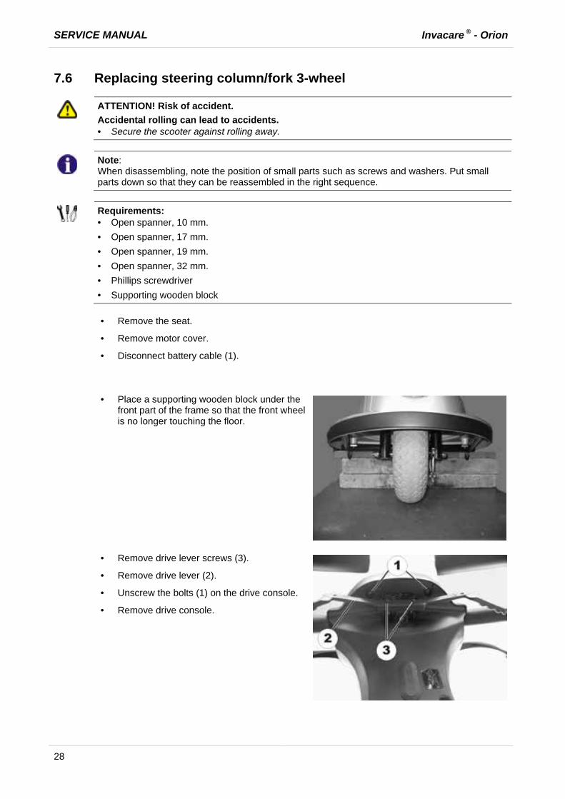
· Remove drive lever screws (3).
· Remove drive lever (2).
· Unscrew the bolts (1) on the drive console.
· Remove drive console.
Invacare ® - Orion SERVICE MANUAL
29
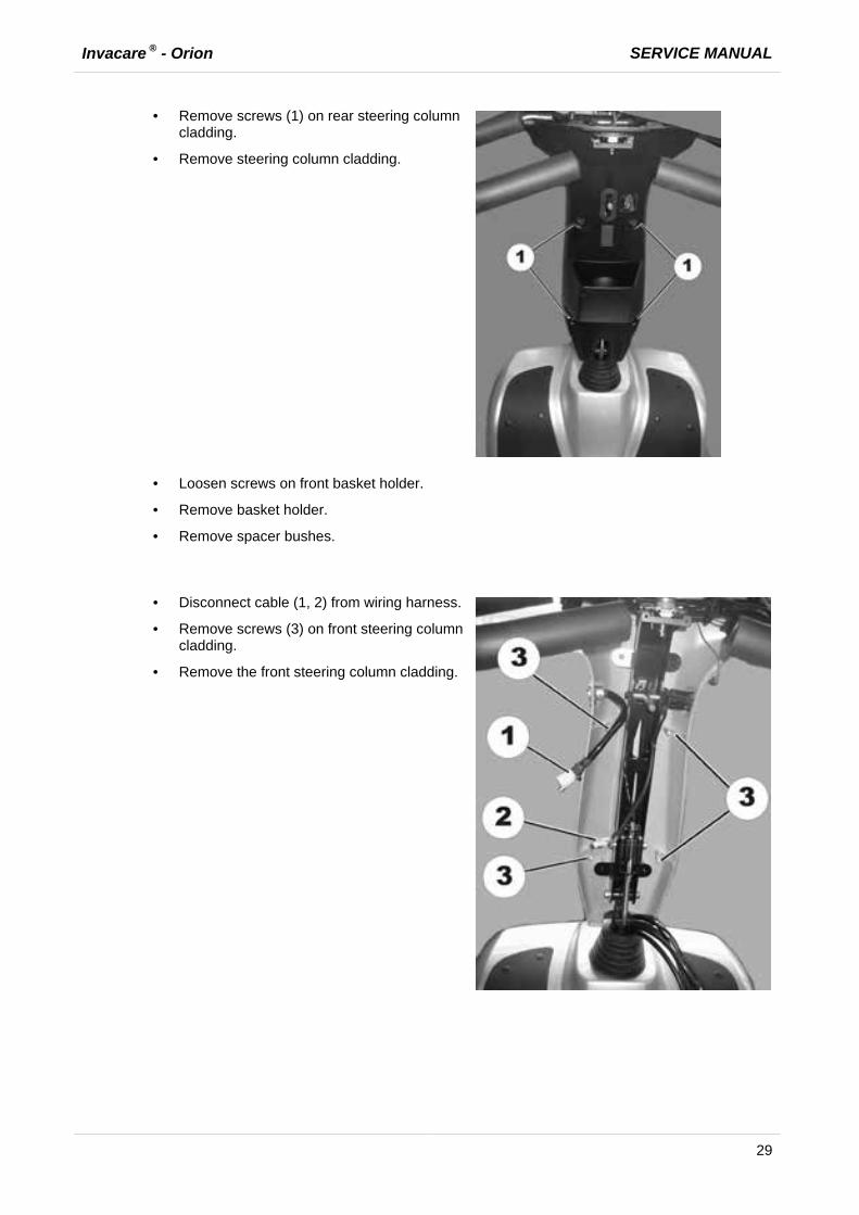
· Remove screws (1) on rear steering column cladding.
· Remove steering column cladding.
· Loosen screws on front basket holder.
· Remove basket holder.
· Remove spacer bushes.
· Disconnect cable (1, 2) from wiring harness.
· Remove screws (3) on front steering column cladding.
· Remove the front steering column cladding.
SERVICE MANUAL Invacare ® - Orion
30
· Release brake cable (see chapter entitled "Replacing brakes" on page 31)
· Unscrew screw at clamp (1).
· Unscrew fixing bolt for steering column and remove.
· Pull steering column out upwards.
Replacing fork 3-wheel:
· Remove rubber mat in foot well.
· Loosen screws in chassis below mat.
· Remove chassis upwards.
· Remove front wheel (see chapter entitled
"Replacing front axle" on page 27)
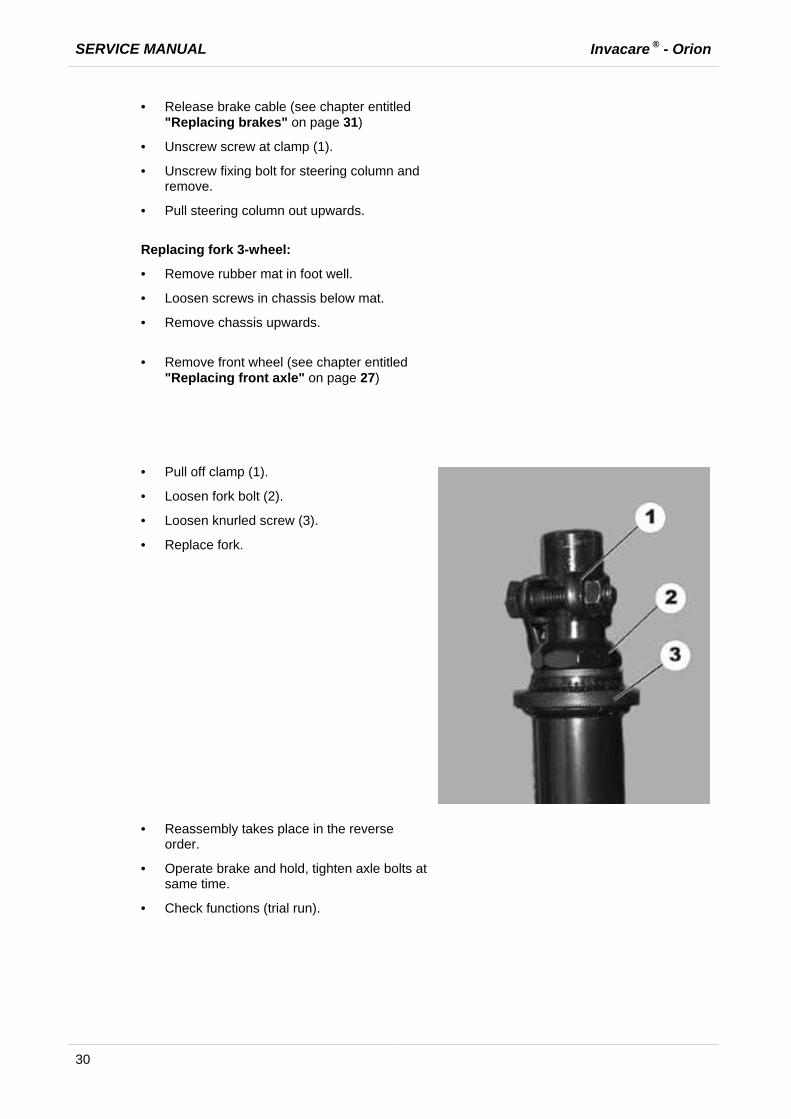
· Pull off clamp (1).
· Loosen fork bolt (2).
· Loosen knurled screw (3).
· Replace fork.
· Reassembly takes place in the reverse order.
· Operate brake and hold, tighten axle bolts at same time.
· Check functions (trial run).

Invacare ® - Orion SERVICE MANUAL
31
7.7 Replacing brakes
ATTENTION! Risk of accident.
Accidental rolling can lead to accidents. · Secure the scooter against rolling away.
Note:
When disassembling, note the position of small parts such as screws and washers. Put small parts down so that they can be reassembled in the right sequence.
Note:
The front axle can only be replaced on the 3-wheel version. The 4-wheel version does not have a replaceable axle.
Requirements:
· Open spanner, 10 mm. · Open spanner, 17 mm. · Open spanner, 19 mm. · Supporting wooden block
· Remove the seat.
· Remove motor cover.
· Separate battery cable.
· Place a supporting wooden block under the
front part of the frame so that the front wheel is no longer touching the floor.
3-wheel version:
· Slacken brake cable (see chapter entitled "Replacing brake cable" on page 33).
· Disconnect brake cable at wheel.
· Loosen axle bolts (1) simultaneously on both sides.
· Pull front axle slowly out.
4-wheel version:
· Slacken both brake cables.
· Disconnect brake cable at affected wheel.
· Loosen wheel bolt.
· Pull wheel and brake off shaft.

SERVICE MANUAL Invacare ® - Orion
32
· Pull brake out of brake drum.
· Replace brake lining or complete brake.
· Reassemble wheel and brake.
· Push wheel and brake onto shaft, or push axle through.
· Operate brake and hold, tighten axle bolts at same time.
· Reassembly of the brake takes place in reverse order
· Adjust braking force on wheel using brake lever setting screw.
· Check braking function while pushing.

Invacare ® - Orion SERVICE MANUAL
33
7.8 Replacing brake cable
ATTENTION! Risk of accident.
Accidental rolling can lead to accidents. · Secure the scooter against rolling away.
Note:
When disassembling, note the position of small parts such as screws and washers. Put small parts down so that they can be reassembled in the right sequence.
Note:
You do NOT need to remove the wheel to replace the brake cable.
Requirements:
· Open spanner, 10 mm. · Phillips screwdriver
· Decrease the brake tension on the wheel
using the setting screw (1).
· Disconnect the brake cable at the wheel (2).
· Disconnect brake cable at steering wheel brake lever.
· Route the brake cable through the cladding.
· Loosen brake lever screw (3) at wheel.
· Replace brake cable.
· Reassembly of the brake cable takes place in reverse order.
· Check braking function while pushing.

SERVICE MANUAL Invacare ® - Orion
34
7.9 Replacing steering linkage/steering rod
ATTENTION! Risk of accident.
Accidental rolling can lead to accidents. · Secure the scooter against rolling away.
Note:
When disassembling, note the position of small parts such as screws and washers. Put small parts down so that they can be reassembled in the right sequence.
Requirements:
· Open spanner, 10 mm. · Open spanner, 12 mm. · Open spanner, 13 mm. · Phillips screwdriver · Circlip pliers · Supporting wooden block
· Remove the seat.
· Remove motor cover.
· Disconnect battery cable (1).
· Dismantle the steering column and the chassis. (See chapter entitled "Replacing steering column/fork 3-wheel" on page 28)

Invacare ® - Orion SERVICE MANUAL
35
Replacing steering link:
· Remove circlip (1) on steering link (2).
· Replace steering link.
· Adjust length of steering link using setting screws (3).
Replacing steering rod:
· Remove circlip (4) on steering rod (5).
· Replace steering rod.
· Adjust tracking by 1° inwards using setting screw (6). (See sketch).
· Reassembly of the steering linkage and/or steering rod takes place in reverse order.
· Check function (trial run).
SERVICE MANUAL Invacare ® - Orion
36
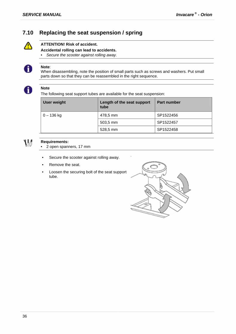
7.10 Replacing the seat suspension / spring
ATTENTION! Risk of accident.
Accidental rolling can lead to accidents. · Secure the scooter against rolling away.
Note:
When disassembling, note the position of small parts such as screws and washers. Put small parts down so that they can be reassembled in the right sequence.
Note
The following seat support tubes are available for the seat suspension:
User weight Length of the seat support tube
Part number
0 – 136 kg 478,5 mm SP1522456
503,5 mm SP1522457
528,5 mm SP1522458
Requirements:
· 2 open spanners, 17 mm
· Secure the scooter against rolling away.
· Remove the seat.
· Loosen the securing bolt of the seat support tube.
Invacare ® - Orion SERVICE MANUAL
37
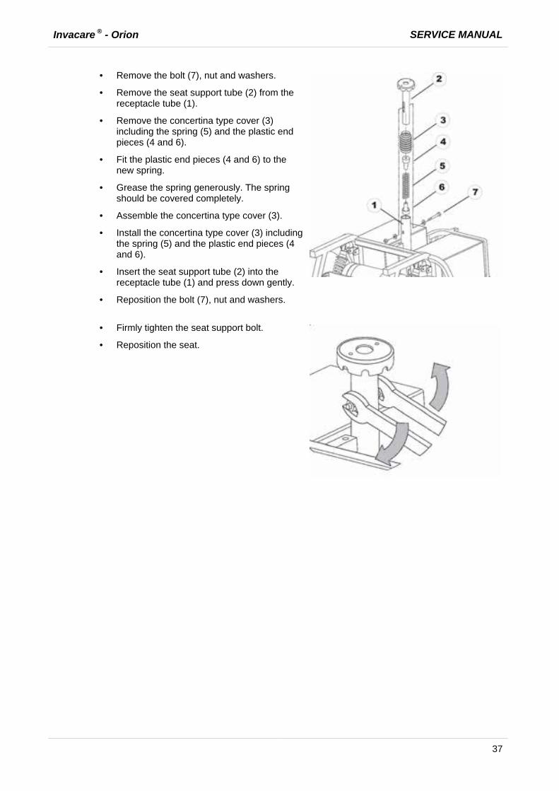
· Remove the bolt (7), nut and washers.
· Remove the seat support tube (2) from the receptacle tube (1).
· Remove the concertina type cover (3) including the spring (5) and the plastic end pieces (4 and 6).
· Fit the plastic end pieces (4 and 6) to the new spring.
· Grease the spring generously. The spring should be covered completely.
· Assemble the concertina type cover (3).
· Install the concertina type cover (3) including the spring (5) and the plastic end pieces (4 and 6).
· Insert the seat support tube (2) into the receptacle tube (1) and press down gently.
· Reposition the bolt (7), nut and washers.
· Firmly tighten the seat support bolt.
· Reposition the seat.

SERVICE MANUAL Invacare ® - Orion
38
7.11 Replacing operating console
ATTENTION!
Burn and scald hazard if power cable is short-circuited! · Turn off the power completely before removing any power supply components of the electric
vehicle! Therefore take out the batteries. · Avoid a bridging of the contacts during measurements on live electrical components!
Note:
The plugs on the operating console cannot be wrongly connected because all plugs have a different size and only fit in one socket.
Requirements:
· Phillips screwdriver
· Remove the seat.
· Remove motor cover.
· Separate battery cable.
· Remove screws (1) below operating console.
· Remove operating console and fold upwards.
· Remove screws (3) on drive lever (2) and remove drive lever.
Invacare ® - Orion SERVICE MANUAL
39
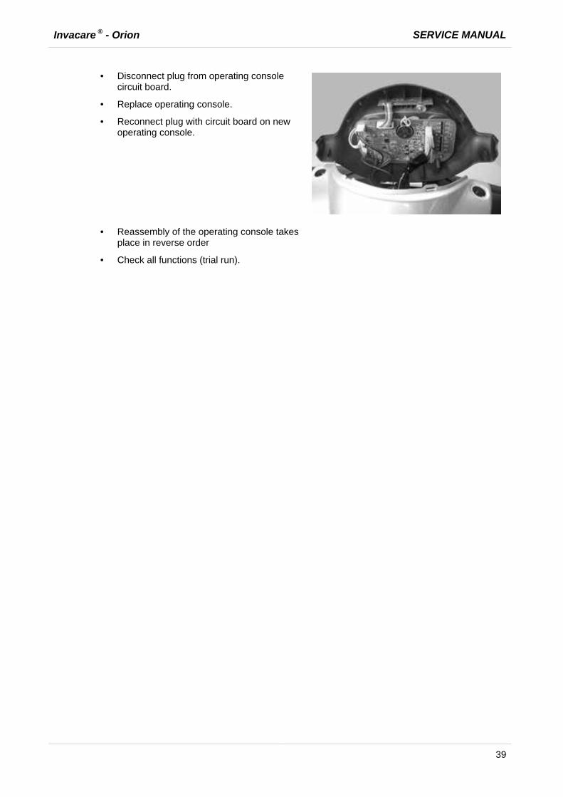
· Disconnect plug from operating console circuit board.
· Replace operating console.
· Reconnect plug with circuit board on new operating console.
· Reassembly of the operating console takes place in reverse order
· Check all functions (trial run).
SERVICE MANUAL Invacare ® - Orion
40
7.12 Replacing bend speed reducer
ATTENTION! Risk of accident.
Accidental rolling can lead to accidents. · Secure the scooter against rolling away.
Note:
When disassembling, note the position of small parts such as screws and washers. Put small parts down so that they can be reassembled in the right sequence.
Requirements:
· Phillips screwdriver · Open spanner, 32 mm.
· Remove the seat.
· Remove motor cover.
· Separate battery cable.
· Remove front and rear steering column
cladding, steering column and housing. (See chapter entitled "Replacing steering column").
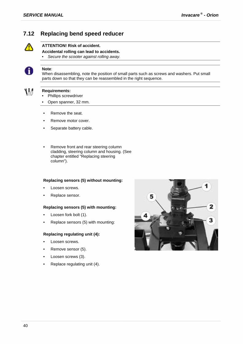
Replacing sensors (5) without mounting:
· Loosen screws.
· Replace sensor.
Replacing sensors (5) with mounting:
· Loosen fork bolt (1).
· Replace sensors (5) with mounting:
Replacing regulating unit (4):
· Loosen screws.
· Remove sensor (5).
· Loosen screws (3).
· Replace regulating unit (4).
Invacare ® - Orion SERVICE MANUAL
41
Adjusting:
· Set steering to straight ahead.
· Align sensor straight using regulating unit.
· Take hold of the sensor and tighten the fork screw.
Check:
· Turn the steering completely to the right and then the left.
· When the steering is turned to its limit, the 3 regulating unit switching knobs should be visible.
· Reassembly takes place in the reverse
order.
· Check functions (trial run).

SERVICE MANUAL Invacare ® - Orion
42
7.13 Replacing the potentiometer
ATTENTION!
Burn and scald hazard if power cable is short-circuited! · Turn off the power completely before removing any power supply components of the electric
vehicle! Therefore take out the batteries. · Avoid a bridging of the contacts during measurements on live electrical components!
ATTENTION! Risk of accident.
Wrong potentiometer setting can result in dangerous driving situations! · Set the new potentiometer to the middle position before inserting.
Requirements:
· Phillips screwdriver · Digital multimeter · Allen key 2m
· Remove the seat.
· Remove motor cover.
· Disconnect battery cable (1).
· Remove screws (1) below operating
console.
· Remove operating console and fold upwards.
· Remove screws (3) on drive lever (2) and remove drive lever.
· Disconnect potentiometer plug (1) from the operating console.

Invacare ® - Orion SERVICE MANUAL
43
· Remove screws (1) on potentiometer.
· Replace potentiometer
· Reconnect potentiometer plug (1) with operating console.
Setting the potentiometer to the middle position:
· Loosen the bolts (1) on the drive lever mounting.
· Twist the potentiometer shaft (2) until the same resistance (approx. 5kOhm) is measured between the central connection cable (3) and both outputs (4).
· Retighten the bolts on the drive lever mounting.
· Check settings and repeat the adjustment if necessary.
· Reassembly of the operating console takes
place in reverse order
· Check all functions (trial run).

SERVICE MANUAL Invacare ® - Orion
44
7.14 Replacing front headlight (lamp)
Requirements:
· Phillips screwdriver
· Remove the seat.
· Remove motor cover.
· Separate battery cable.
3-wheel version
· Remove screw (1) on front headlight under front cladding.
4-wheel version
· Remove screw (1) on front headlight under front cladding.
· Remove headlight.
· Disconnect cable from wiring harness.
· Remove screws (1) on headlight glass.
· Remove headlight glass.
· Replace bulb(s) in headlight.

Invacare ® - Orion SERVICE MANUAL
45
· Reassembly of the headlight takes place in reverse order.
· Check function
SERVICE MANUAL Invacare ® - Orion
46
7.15 Replacing the front direction indicators
Requirements:
· Phillips screwdriver.
· Remove the seat.
· Remove motor cover.
· Separate battery cable.
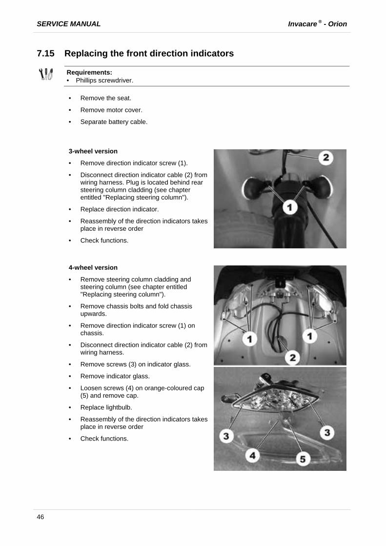
3-wheel version
· Remove direction indicator screw (1).
· Disconnect direction indicator cable (2) from wiring harness. Plug is located behind rear steering column cladding (see chapter entitled "Replacing steering column").
· Replace direction indicator.
· Reassembly of the direction indicators takes place in reverse order
· Check functions.
4-wheel version
· Remove steering column cladding and steering column (see chapter entitled "Replacing steering column").
· Remove chassis bolts and fold chassis upwards.
· Remove direction indicator screw (1) on chassis.
· Disconnect direction indicator cable (2) from wiring harness.
· Remove screws (3) on indicator glass.
· Remove indicator glass.
· Loosen screws (4) on orange-coloured cap (5) and remove cap.
· Replace lightbulb.
· Reassembly of the direction indicators takes place in reverse order
· Check functions.
Invacare ® - Orion SERVICE MANUAL
47
7.16 Replacing centre brake light
ATTENTION!
Burn and scald hazard if power cable is short-circuited! · Turn off the power completely before removing any power supply components of the electric
vehicle! Therefore take out the batteries. · Avoid a bridging of the contacts during measurements on live electrical components!
Note:
When disassembling, note the position of small parts such as screws and washers. Put small parts down so that they can be reassembled in the right sequence.
Requirements:
· Phillips screwdriver
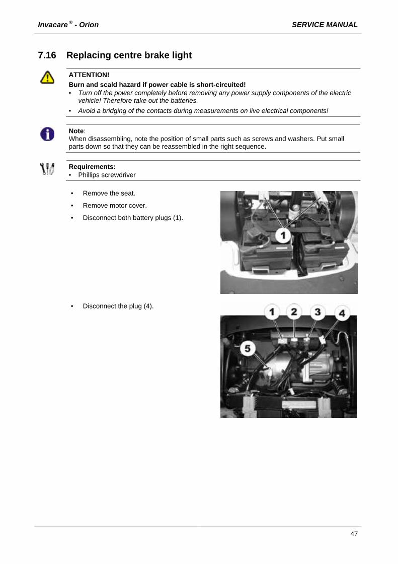
· Remove the seat.
· Remove motor cover.
· Disconnect both battery plugs (1).
· Disconnect the plug (4).

SERVICE MANUAL Invacare ® - Orion
48
· Remove the bolt (1) on the rear panelling.
· Lift the rear panelling upwards.
· Remove screws (1) on brake light.
· Replace brake light.
· Reassembly of the brake light takes place in reverse order.
· Check functions (trial run).
Invacare ® - Orion SERVICE MANUAL
49
7.17 Replacing rear lights/direction indicators
ATTENTION!
Burn and scald hazard if power cable is short-circuited! · Turn off the power completely before removing any power supply components of the electric
vehicle! Therefore take out the batteries. · Avoid a bridging of the contacts during measurements on live electrical components!
Note:
When disassembling, note the position of small parts such as screws and washers. Put small parts down so that they can be reassembled in the right sequence.
Requirements:
· Phillips screwdriver
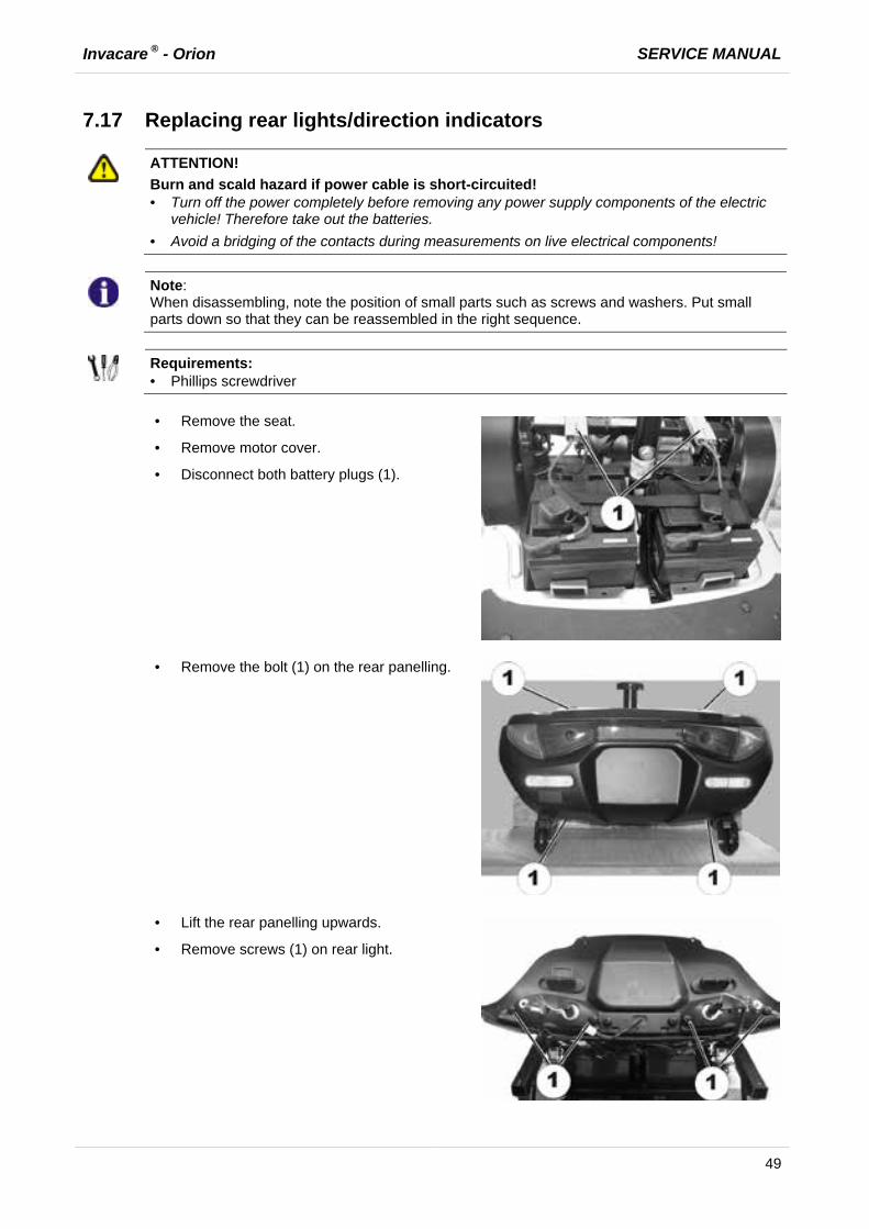
· Remove the seat.
· Remove motor cover.
· Disconnect both battery plugs (1).
· Remove the bolt (1) on the rear panelling.
· Lift the rear panelling upwards.
· Remove screws (1) on rear light.
SERVICE MANUAL Invacare ® - Orion
50
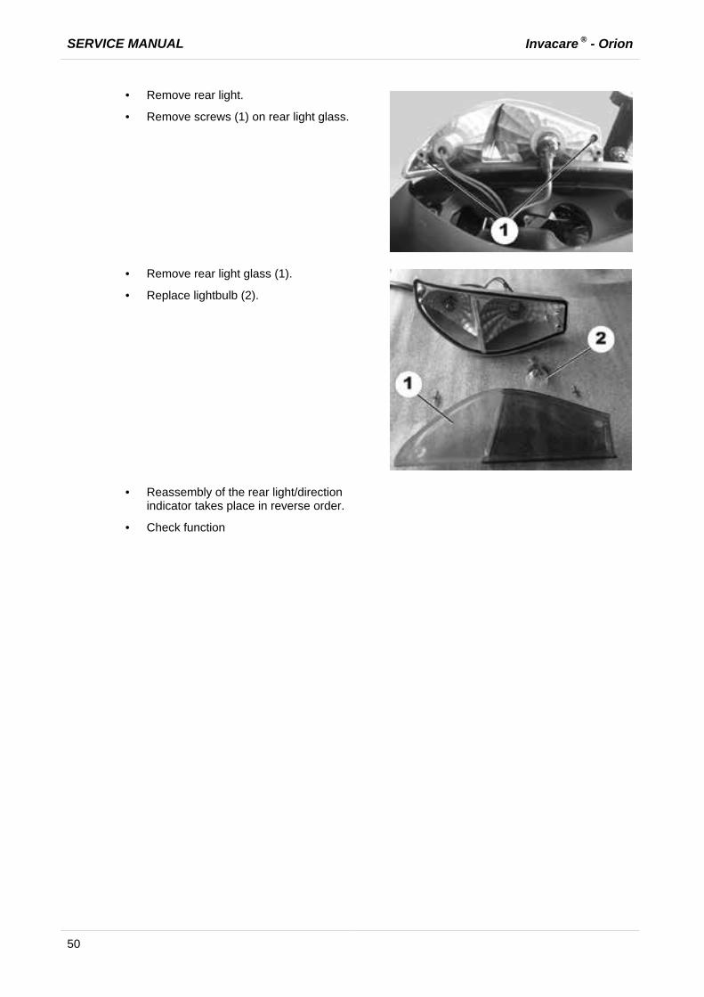
· Remove rear light.
· Remove screws (1) on rear light glass.
· Remove rear light glass (1).
· Replace lightbulb (2).
· Reassembly of the rear light/direction indicator takes place in reverse order.
· Check function

Invacare ® - Orion SERVICE MANUAL
51
7.18 Replacing the electronic module
ATTENTION! Risk of accident.
When parking the scooter on the scooters support wheels it is no longer slowed by the engine brake. The scooter can roll away out of control. · Place the scooter rear frame on a supporting wooden block before you remove the wheels.
ATTENTION!
Burn and scald hazard if power cable is short-circuited! · Turn off the power completely before removing any power supply components of the electric
vehicle! Therefore take out the batteries. · Avoid a bridging of the contacts during measurements on live electrical components!
WARNING!
Any changes to the drive program can affect the driving characteristics and the tipping stability of the mobility aid! · Changes to the drive program may only be carried out by trained Invacare® specialist
dealers! · Invacare® can only give a warranty for safe mobility aid driving behaviour - especially tipping
stability - for unaltered standard drive programs!
ATTENTION! Risk of accident.
Accidental rolling can lead to accidents. · Secure the scooter against rolling away.
Note:
The electronic system is supplied with a standard drive program. If you have carried out customer-specific modifications to the drive program, you will have to make these changes again after installing the new electronic module.
Note:
When disassembling, note the position of small parts such as screws and washers. Put small parts down so that they can be reassembled in the right sequence.
Note:
The plugs on the electronic module cannot be wrongly connected because all plugs have a different size and only fit in one socket.
Requirements:
· Open spanner, 10 mm. · Open spanner, 17 mm. · Rubber hammer · Phillips screwdriver · Supporting wooden block · To adapt the drive program: programming software or hand programming device and
electronic system installation manual, available from Invacare®.
SERVICE MANUAL Invacare ® - Orion
52
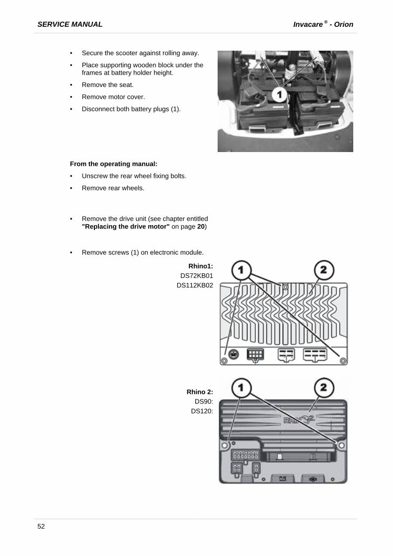
· Secure the scooter against rolling away.
· Place supporting wooden block under the frames at battery holder height.
· Remove the seat.
· Remove motor cover.
· Disconnect both battery plugs (1).
From the operating manual:
· Unscrew the rear wheel fixing bolts.
· Remove rear wheels.
· Remove the drive unit (see chapter entitled
"Replacing the drive motor" on page 20)
· Remove screws (1) on electronic module.
Rhino1: DS72KB01
DS112KB02
Rhino 2: DS90:
DS120:

Invacare ® - Orion SERVICE MANUAL
53
· Remove screws (1) on electronic module.
· Replace electronic module (2).
· Reassembly of the drive and the electronic
module takes place in reverse order.
· Load drive program onto electronic module. See electronic software description.
· Check all functions (trial run).
SERVICE MANUAL Invacare ® - Orion
54
7.19 Updating software Invacare is continuously carrying out further development and improvements to drive programs for electric vehicles. For this reason, you should always check whether the drive program version number is up-to-date when carrying out any repairs or regular maintenance. If a newer version is available, the drive program must be updated. The procedure for updating the drive program is described in the wizard software operating manual.
NOTE:
The electronic system is supplied with a standard drive program. If you have carried out customer-specific modifications to the drive program, you will have to make these changes again after installing the new electronic module.
WARNING!
Any changes to the drive program can affect the driving characteristics and the tipping stability of the mobility aid! · Changes to the drive program may only be carried out by trained Invacare® specialist
dealers! · Invacare® can only give a warranty for safe mobility aid driving behaviour - especially tipping
stability - for unaltered standard drive programs!
Requirements:
· Dynamic® Wizard software · Operating manual for Wizard software · For further information on other requirements - such as the minimum system configuration of
the PC to be used for programming, necessary programming cables - see the user manual of the Wizard software. You find the latest version of the user manual in the download area on http://www.dynamiccontrols.com/.
Invacare ® - Orion SERVICE MANUAL
55
8 Accessories
8.1 Installing the windshield
Requirements:
· 13 mm open-ended wrench · 14 mm open-ended wrench
· Remove the rear view mirror and the
stoppers of the plastic cover on the handlebars.
· Remove the threaded bolts of the rear view mirror holder.
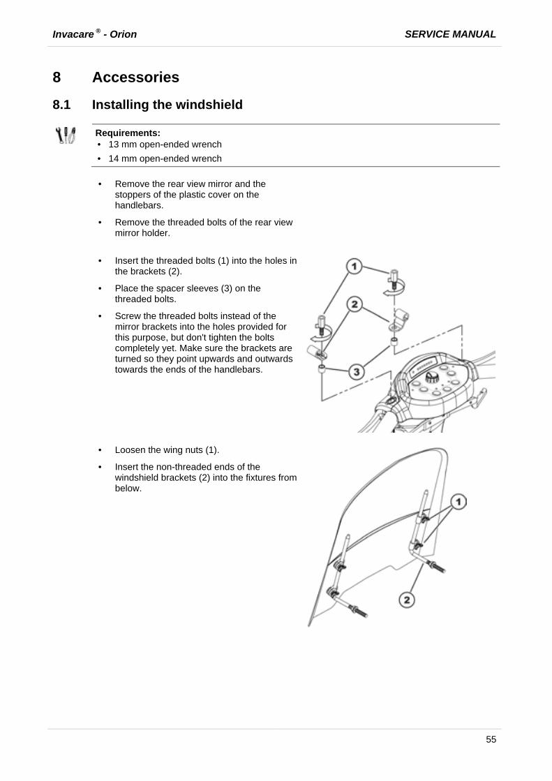
· Insert the threaded bolts (1) into the holes in
the brackets (2).
· Place the spacer sleeves (3) on the threaded bolts.
· Screw the threaded bolts instead of the mirror brackets into the holes provided for this purpose, but don't tighten the bolts completely yet. Make sure the brackets are turned so they point upwards and outwards towards the ends of the handlebars.
· Loosen the wing nuts (1).
· Insert the non-threaded ends of the windshield brackets (2) into the fixtures from below.
SERVICE MANUAL Invacare ® - Orion
56
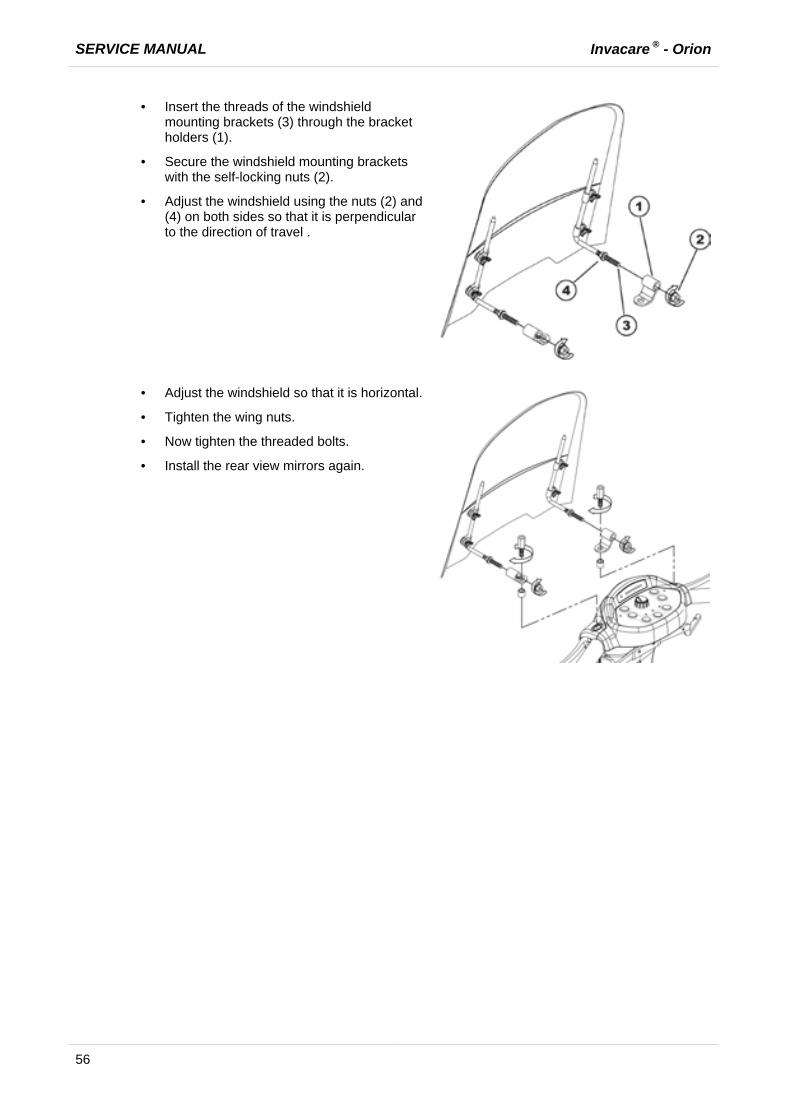
· Insert the threads of the windshield mounting brackets (3) through the bracket holders (1).
· Secure the windshield mounting brackets with the self-locking nuts (2).
· Adjust the windshield using the nuts (2) and (4) on both sides so that it is perpendicular to the direction of travel .
· Adjust the windshield so that it is horizontal.
· Tighten the wing nuts.
· Now tighten the threaded bolts.
· Install the rear view mirrors again.


