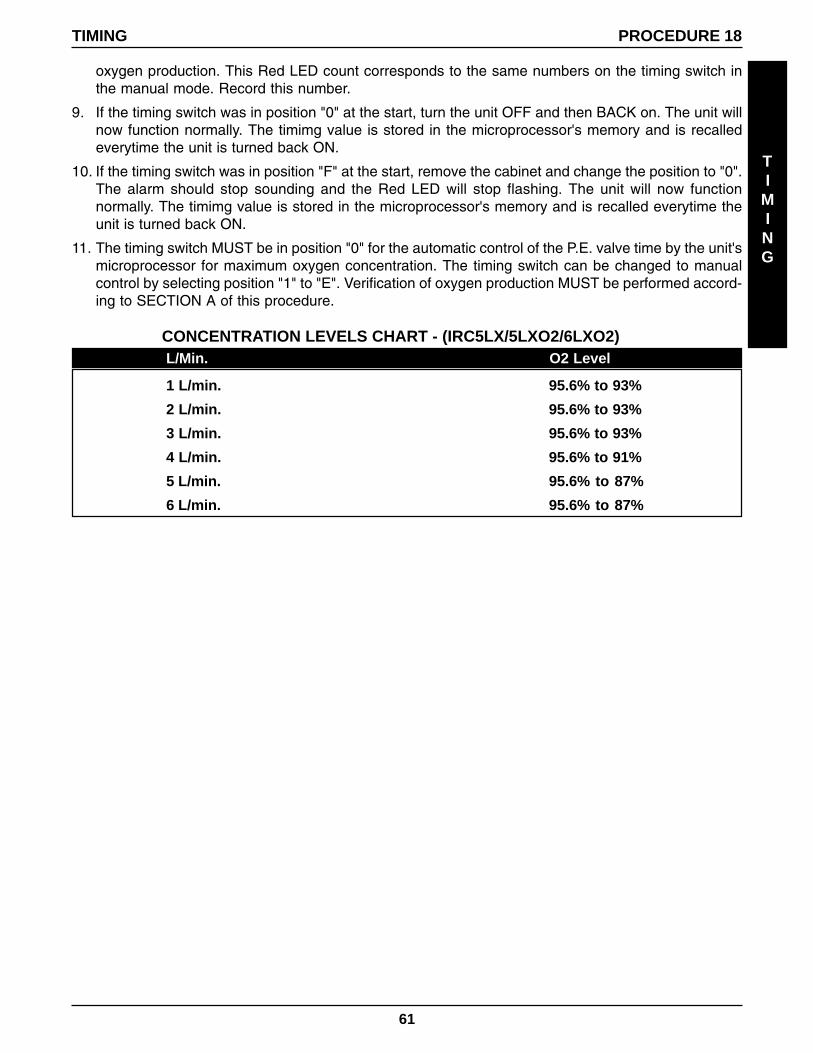
INVACARE OXYGEN CONCENTRATORS INVACARE 5 & 6 Model 5LXO2 with SensO 2 Model 5LXO2T with SensO 2 Model 6LXO2 with SensO 2 Model 6LXO2T with SensO 2 Model 6LXO2H with SensO 2 Model 6LXO2HT with SensO 2 INVACARE 3 & 5 Model 3LX Model 5LX SERVICE MANUAL DEALER: KEEP THIS MANUAL. THE PROCEDURES IN THIS MANUAL MUST BE PERFORMED BY AN AUTHORIZED DEALER ONLY.
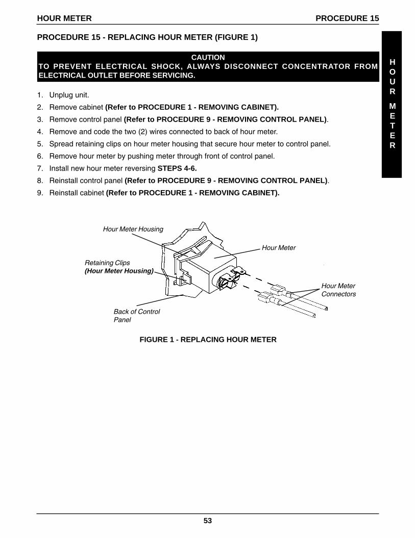
Transcript
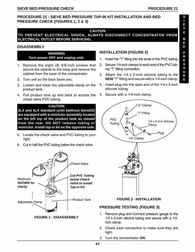
INVACAREOXYGEN CONCENTRATORS
INVACARE 5 & 6Model 5LXO2
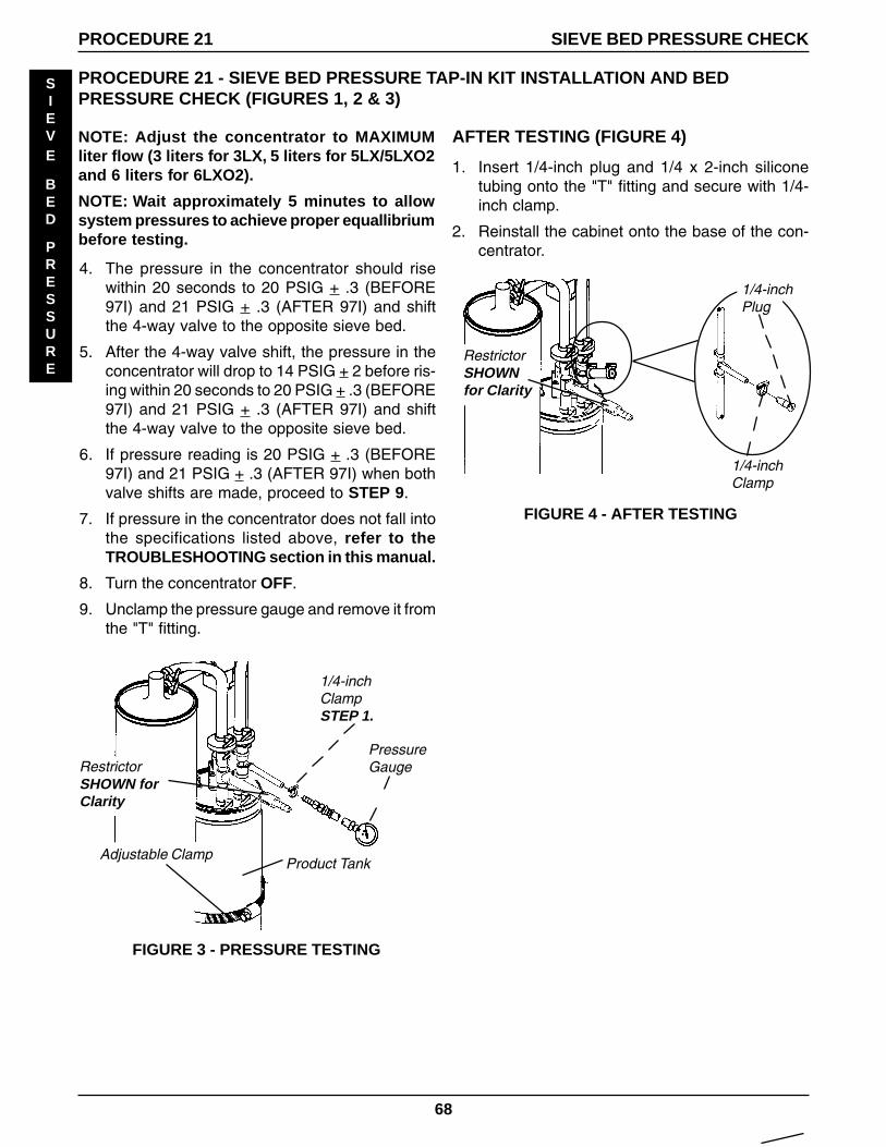
with SensO2
Model 5LXO2T with SensO2
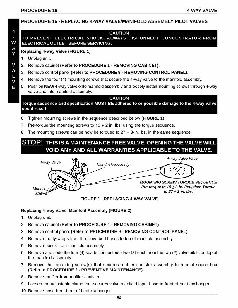
Model 6LXO2 with SensO2
Model 6LXO2T with SensO2
Model 6LXO2H with SensO2
Model 6LXO2HT with SensO2
INVACARE 3 & 5Model 3LXModel 5LX
SERVICE MANUALDEALER: KEEP THIS MANUAL. THE PROCEDURES IN THIS MANUAL MUSTBE PERFORMED BY AN AUTHORIZED DEALER ONLY.
2
SPECIAL NOTES
SPECIAL
NOTES
SPECIAL NOTES
WARNING/CAUTION notices used in this manual apply to hazards or unsafe practiceswhich could result in personal injury or property damage.
NOTICE
THE INFORMATION CONTAINED IN THIS DOCUMENT IS SUBJECT TO CHANGE WITH-OUT NOTICE.
WARNINGDO NOT OPERATE THIS EQUIPMENT WITHOUT FIRST
READING AND UNDERSTANDING THIS MANUAL. IF YOUARE UNABLE TO UNDERSTAND THE WARNINGS AND
INSTRUCTIONS, CONTACT A HEALTHCAREPROFESSIONAL (DOCTOR - THERAPIST) BEFORE
ATTEMPTING TO USE THIS EQUIPMENT - OTHERWISEINJURY OR DAMAGE MAY RESULT.
Compressor Top End Rebuild - 3 LiterRebuilding Thomas Model 2638 or2618.......................................................... 24
Compressor Top End Rebuild - 5 and 6 LiterRebuilding Thomas Model 2639 or2619.......................................................... 29Rebuilding Thomas Model 2650 ................ 33
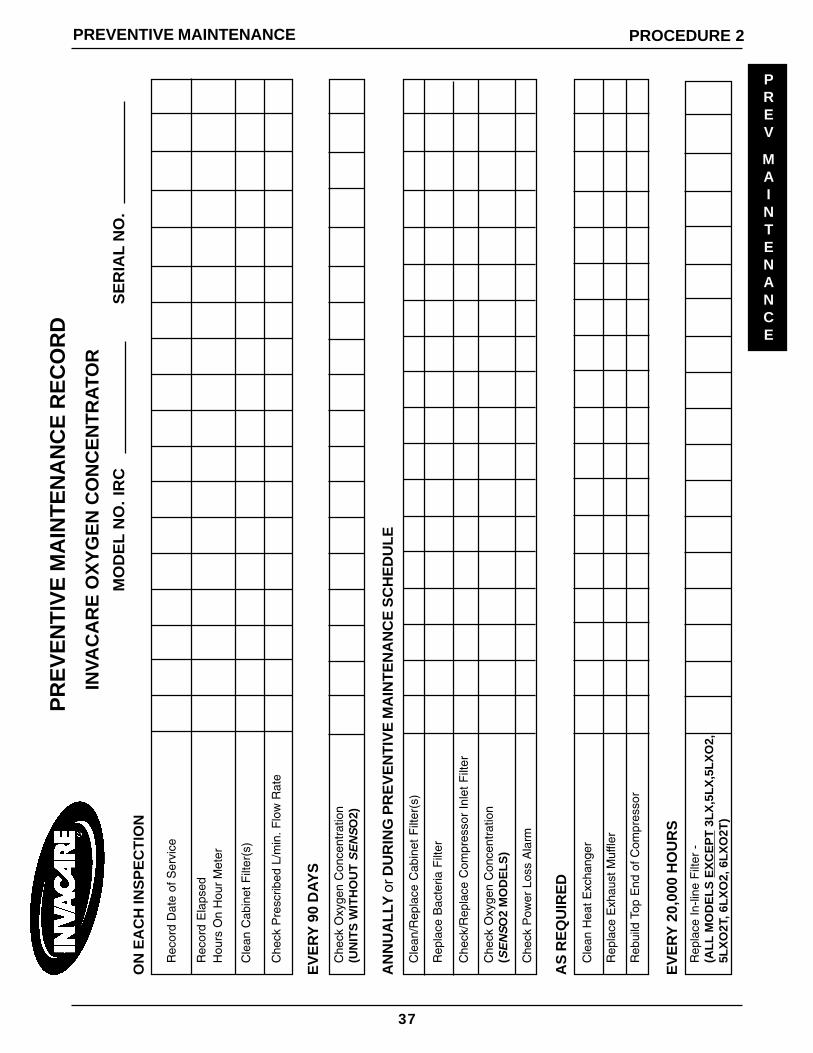
Preventive Maintenance Record .................. 37
WARNINGThe use of oxygen therapy requires that special care be taken to reduce the risk of fire. Anymaterials that will burn in air, and some that will not, are easily ignited and burn rapidly in highconcentrations of oxygen. For safety concerns, it is necessary that all sources of ignition be keptaway from the product and preferably out of the room in which it is being used. NO SMOKINGsigns should be prominently displayed.
A spontaneous and violent ignition may occur if oil, grease or greasy substances come in contactwith oxygen under pressure. These substances MUST be kept away from the oxygen concentra-tor, tubing and connections, and all other oxygen equipment. DO NOT use any lubricants unlessrecommended by Invacare.
For optimum performance, Invacare recommends that each concentrator be on and running fora minimum of 30 minutes at a time. Shorter periods of operation may be harmful for maximumproduct life.
If it has a damaged cord or plug, if it is not working properly, if it has been dropped ordamaged, or dropped into water, call Qualified Service Personnel for examination and repair.
Keep the cord away from HEATED or HOT surfaces.
NEVER drop or insert any object into any opening.
NEVER block the air openings of the product or place it on a soft surface, such as a bed or couch,where the air opening may be blocked. Keep the openings free from lint, hair and the like.
Fill humidifier with water to the level shown by the manufacturer. DO NOT overfill.
Invacare recommends that Crush-Proof oxygen tubing (supplied by Invacare) be used with thisproduct and NOT exceed 50 ft. (15.2m) in length.
READ THE FOLLOWING INFORMATION BEFORE OPERATING THIS PRODUCT.
MAINTENANCE
The Invacare Oxygen Concentrator was specifically designed to minimize routine preventativemaintenance at intervals of once per year. Only professionals of the healthcare field or personsfully conversant with this process such as authorized or factory trained personnel shouldperform preventative maintenance or performance adjustments on the oxygen concentrator.
RADIO FREQUENCY INTERFERENCE
Most electronic equipment is influenced by Radio Frequency Interference (RFI). CAUTION shouldbe exercised with regard to the use of portable communications equipment in the area aroundsuch equipment.
5
SAFETY SUMMARY (Continued)
SAFETY SUMMARY
SAFETY
SUMMARY
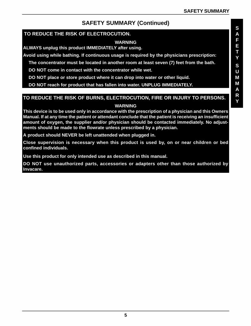
WARNINGALWAYS unplug this product IMMEDIATELY after using.
Avoid using while bathing. If continuous usage is required by the physicians prescription:
The concentrator must be located in another room at least seven (7) feet from the bath.
DO NOT come in contact with the concentrator while wet.
DO NOT place or store product where it can drop into water or other liquid.
DO NOT reach for product that has fallen into water. UNPLUG IMMEDIATELY.
TO REDUCE THE RISK OF ELECTROCUTION.
TO REDUCE THE RISK OF BURNS, ELECTROCUTION, FIRE OR INJURY TO PERSONS.
WARNINGThis device is to be used only in accordance with the prescription of a physician and this OwnersManual. If at any time the patient or attendant conclude that the patient is receiving an insufficientamount of oxygen, the supplier and/or physician should be contacted immediately. No adjust-ments should be made to the flowrate unless prescribed by a physician.
A product should NEVER be left unattended when plugged in.
Close supervision is necessary when this product is used by, on or near children or bedconfined individuals.
Use this product for only intended use as described in this manual.
DO NOT use unauthorized parts, accessories or adapters other than those authorized byInvacare.
6
SAFETY SUMMARY
SAFETY SUMMARY (Continued)SAFETY
SUMMARY
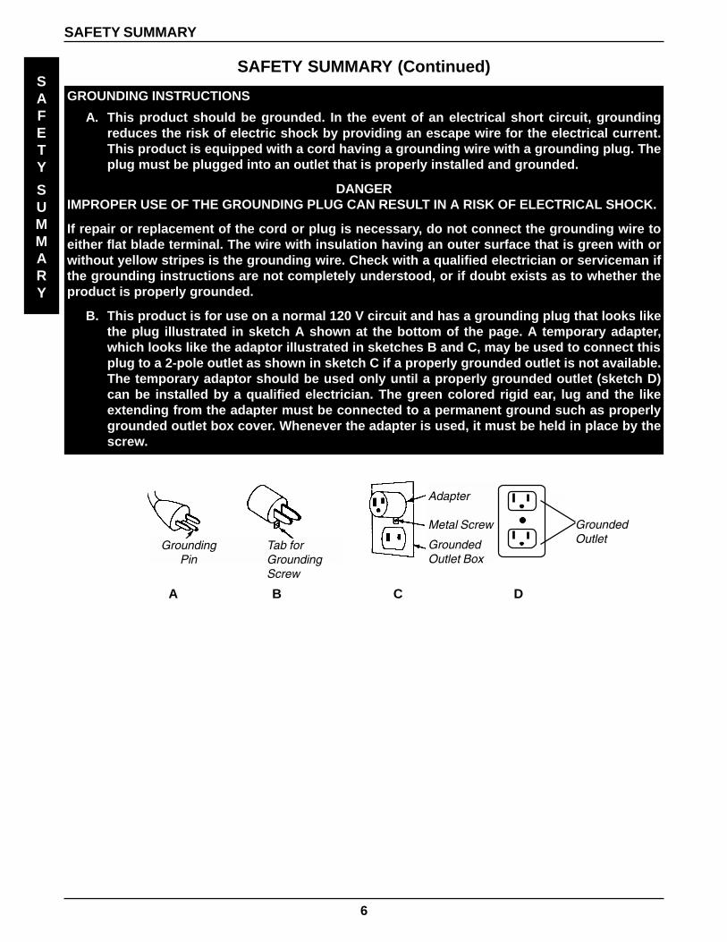
GROUNDING INSTRUCTIONS
A. This product should be grounded. In the event of an electrical short circuit, groundingreduces the risk of electric shock by providing an escape wire for the electrical current.This product is equipped with a cord having a grounding wire with a grounding plug. Theplug must be plugged into an outlet that is properly installed and grounded.
DANGERIMPROPER USE OF THE GROUNDING PLUG CAN RESULT IN A RISK OF ELECTRICAL SHOCK.
If repair or replacement of the cord or plug is necessary, do not connect the grounding wire toeither flat blade terminal. The wire with insulation having an outer surface that is green with orwithout yellow stripes is the grounding wire. Check with a qualified electrician or serviceman ifthe grounding instructions are not completely understood, or if doubt exists as to whether theproduct is properly grounded.
B. This product is for use on a normal 120 V circuit and has a grounding plug that looks likethe plug illustrated in sketch A shown at the bottom of the page. A temporary adapter,which looks like the adaptor illustrated in sketches B and C, may be used to connect thisplug to a 2-pole outlet as shown in sketch C if a properly grounded outlet is not available.The temporary adaptor should be used only until a properly grounded outlet (sketch D)can be installed by a qualified electrician. The green colored rigid ear, lug and the likeextending from the adapter must be connected to a permanent ground such as properlygrounded outlet box cover. Whenever the adapter is used, it must be held in place by thescrew.
GroundingPin
Tab forGroundingScrew
Adapter
Metal Screw
GroundedOutlet Box
GroundedOutlet
A B C D
7
FEATURES
FEATURES
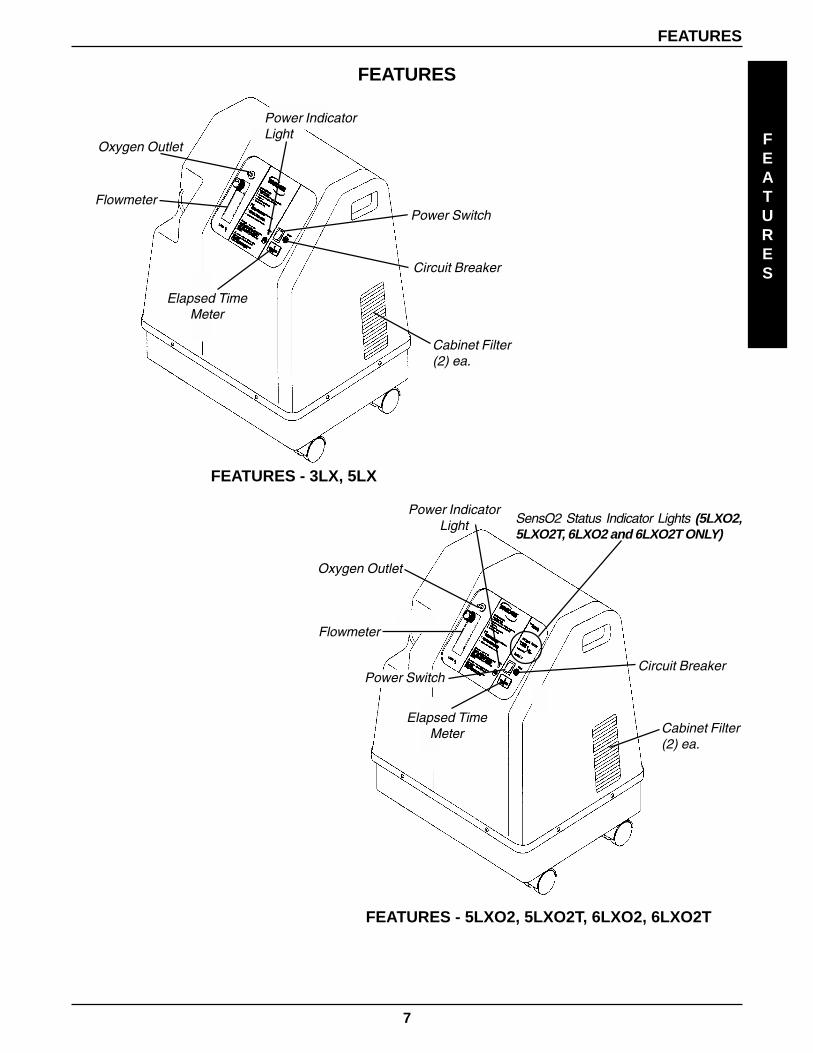
FEATURES
Power Switch
Elapsed TimeMeter Cabinet Filter
(2) ea.
Circuit Breaker
Oxygen Outlet
Flowmeter
Oxygen Outlet
Power IndicatorLight
Power Switch
Cabinet Filter(2) ea.
FEATURES - 3LX, 5LX
Circuit Breaker
Flowmeter
Power IndicatorLight
Elapsed TimeMeter
SensO2 Status Indicator Lights (5LXO2,5LXO2T, 6LXO2 and 6LXO2T ONLY)
FEATURES - 5LXO2, 5LXO2T, 6LXO2, 6LXO2T
8
SPECIFICATIONS
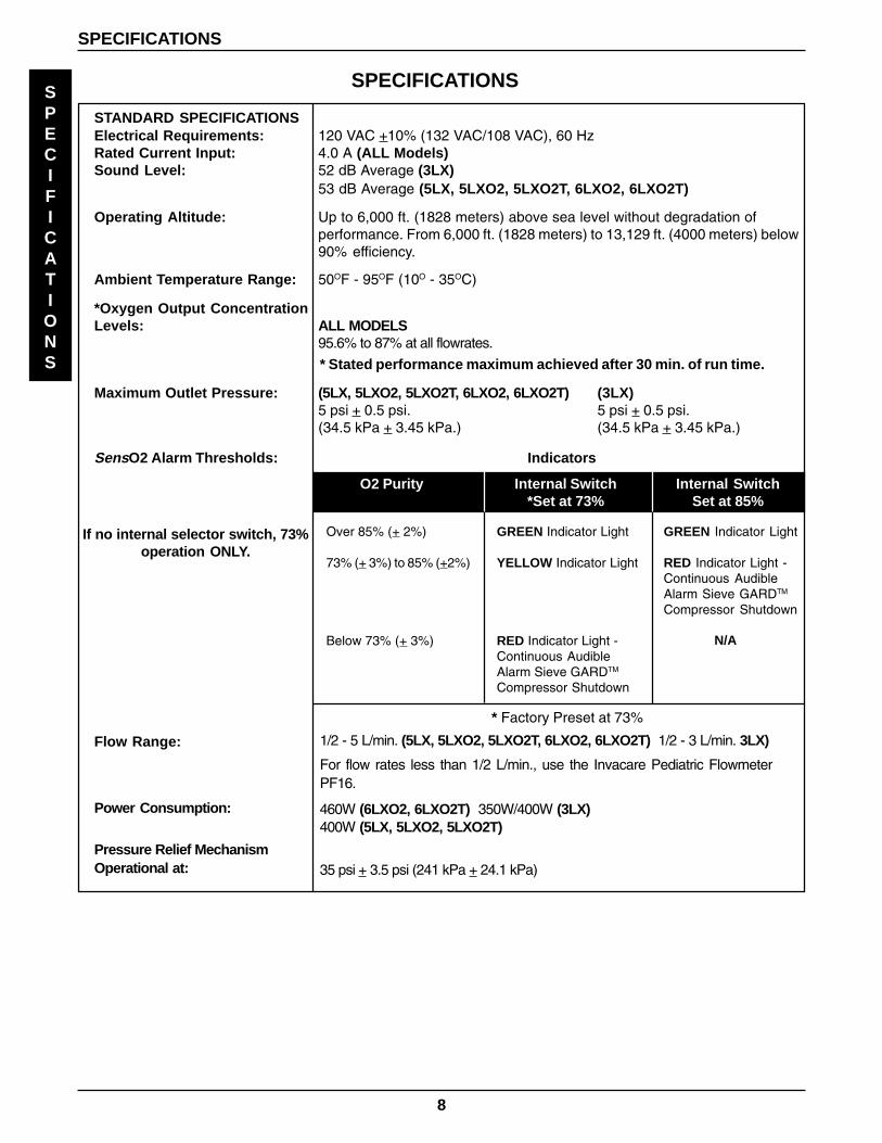
STANDARD SPECIFICATIONSElectrical Requirements: 120 VAC +10% (132 VAC/108 VAC), 60 HzRated Current Input: 4.0 A (ALL Models)Sound Level: 52 dB Average (3LX)
53 dB Average (5LX, 5LXO2, 5LXO2T, 6LXO2, 6LXO2T)
Operating Altitude: Up to 6,000 ft. (1828 meters) above sea level without degradation ofperformance. From 6,000 ft. (1828 meters) to 13,129 ft. (4000 meters) below90% efficiency.
Ambient Temperature Range: 50OF - 95OF (10O - 35OC)
SPECIFICATIONS
SPECIFICATIONS
* Stated performance maximum achieved after 30 min. of run time.
RECOMMENDED END-USER GUIDELINES FOR OPTIMUM PERFORMANCE:
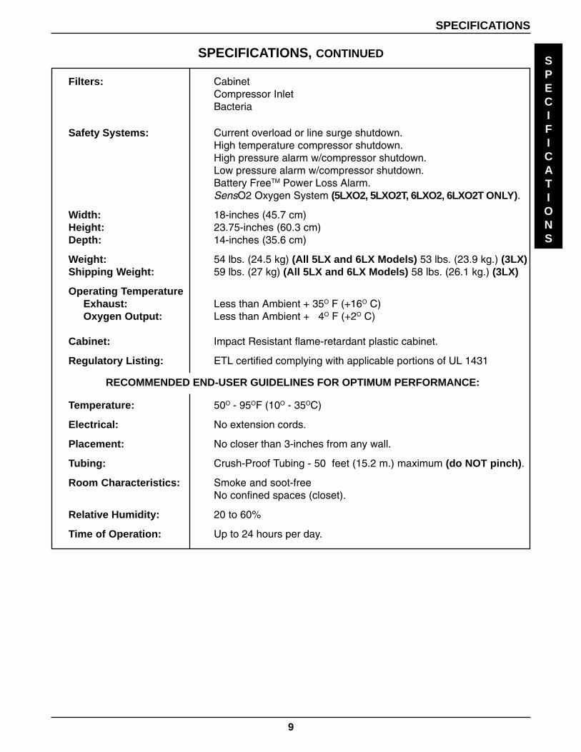
Filters: CabinetCompressor InletBacteria
Safety Systems: Current overload or line surge shutdown.High temperature compressor shutdown.High pressure alarm w/compressor shutdown.Low pressure alarm w/compressor shutdown.Battery FreeTM Power Loss Alarm.SensO2 Oxygen System (5LXO2, 5LXO2T, 6LXO2, 6LXO2T ONLY).
Regulatory Listing: ETL certified complying with applicable portions of UL 1431
Temperature: 50O - 95OF (10O - 35OC)
Electrical: No extension cords.
Placement: No closer than 3-inches from any wall.
Tubing: Crush-Proof Tubing - 50 feet (15.2 m.) maximum (do NOT pinch).
Room Characteristics: Smoke and soot-freeNo confined spaces (closet).
Relative Humidity: 20 to 60%
Time of Operation: Up to 24 hours per day.
10
SHIPPING AND HANDLING INSTRUCTIONSThis Service Manual describes, in detail, the Invacare 3, 5 and 6 Oxygen Concentrators. It has beencarefully written to explain concentrator operation, service and preventative maintenance. Beforeyou install and operate the concentrator, please refer to OWNER'S MANUAL.
SHIPPING AND HANDLING
SHIPPING/HANDLING
The Invacare concentrator should always be kept in the upright position to prevent cabinet damage whilebeing transported. The shipping container has been designed to assure maximum protection of the con-centrator.
If the concentrator is to be reshipped by common carrier, it should be packed in a new carton. Additionalcartons are available from Invacare.
The air compressor suspension system has been engineered to withstand severe motion and orientation.
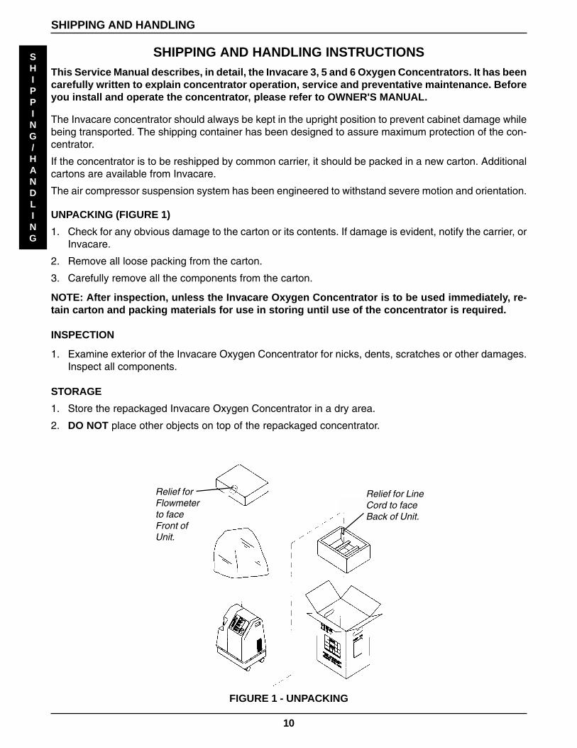
UNPACKING (FIGURE 1)
1. Check for any obvious damage to the carton or its contents. If damage is evident, notify the carrier, orInvacare.
2. Remove all loose packing from the carton.
3. Carefully remove all the components from the carton.
NOTE: After inspection, unless the Invacare Oxygen Concentrator is to be used immediately, re-tain carton and packing materials for use in storing until use of the concentrator is required.
INSPECTION
1. Examine exterior of the Invacare Oxygen Concentrator for nicks, dents, scratches or other damages.Inspect all components.
STORAGE
1. Store the repackaged Invacare Oxygen Concentrator in a dry area.
2. DO NOT place other objects on top of the repackaged concentrator.
FIGURE 1 - UNPACKING
Relief for LineCord to faceBack of Unit.
Relief forFlowmeterto faceFront ofUnit.
11
INSTALLATION
INSTALLATION / SEQUENCE OF OPERATIONMODEL 3LX and MODELS 5LX,5LXO2, 5LXO2T, 6LXO2, 6LXO2T
INSTALLATION / VERIFICATION OF BATTERY FREETM POWER LOSS ALARM
When your new Invacare concentrator arrives, it should be checked for proper operating conditions.
1. If the unit has been in below-freezing temperatures, allow it to warm up to room temperature (approxi-mately 30 minutes) before operating.
2. The concentrator will need to be turned on for 4 to 5 seconds to charge the Battery FreeTM Power Loss Alarm.Connect power cord to outlet and turn the concentrator on. Turn flow control knob counterclockwise and flow willbegin immediately. Set flow rate of the Invacare 3 to 3 L/min., Invacare 5 to 5 L/min. and the Invacare 6 to 6 L/min.Turn unit off.
3. Unplug the power cord and press On/Off switch to the ON position. An intermittent audible alarm willsound. This confirms proper operation of the Battery FreeTM Power Loss Alarm. Turn On/Off switchOFF.
4. Connect cord to outlet and turn on concentrator. Unit will sound 3 BEEPS on startup.
5. Check the oxygen concentration per specifications after 30-40 minutes running time.
SEQUENCE OF OPERATION
Applying 120 VAC via the power switch energizes the compressor motor, hour meter, cooling fan and theprinted circuit (P.C.) board.
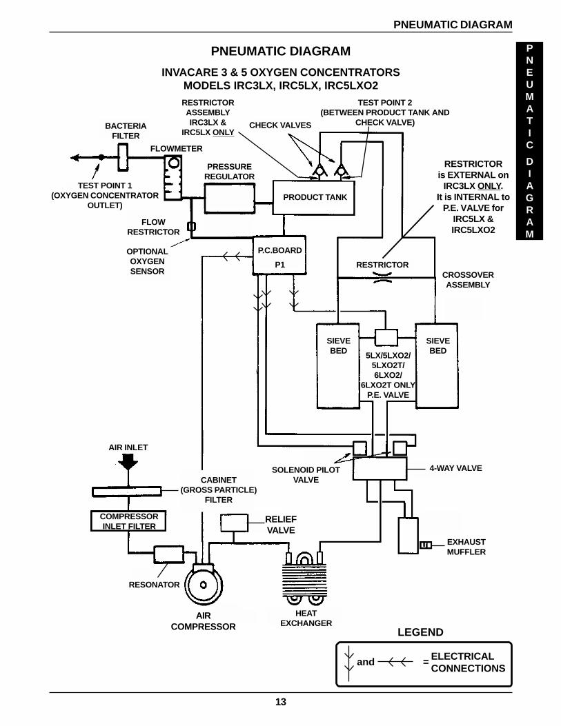
Room air enters the compressor via the cabinet filter, compressor inlet filter, and sound muffler. The air iscompressed by the wobble pistons in the compressor to a pressure of 20 PSI (137.72 kPa) BEFORESerial No. "97K" or 21 PSI (144.79 kPa) AFTER Serial No. "97K".
As increased pressure creates increased temperature, a heat exchanger is utilized to lower the tempera-ture by 20O F (6.7O C) before the air enters the 4-way valve. It is then channeled to a sieve bed containingthe adsorption material. A restrictor downstream of the sieve bed causes pressure to build up inside thesieve bed which is necessary for the adsorption process. A small amount of relatively pure oxygen entersthe top of the second bed with the balance entering a storage tank. The nitrogen removed is exhaustedback from the bed through the four-way valve into room air. A muffler is located at the exhaust end of thevalve to muffle the sound of the exhaust as it exits the concentrator.
The oxygen not being used to exhaust is channeled into the storage tank. The pressurized oxygen isregulated down to 5 PSI (34.4 kPa), enters an accurate flow-measuring device, flows through a bacterialfilter, a check valve and out to the patient.
The electrical activation of the 4-way valve is accomplished every 8 to 21 seconds by the pressure sensorand P.C. board electronics when the pressure set point of 20 + 3 PSI (137.72 + 51.32 kPa) BEFORESerial No. "97K" or 21 + 3 PSI (144.79 + 51.32 kPa) AFTER Serial No. "97K" is reached. The timebetween cycles is dependent on altitude, flow rate and internal environmental factors.
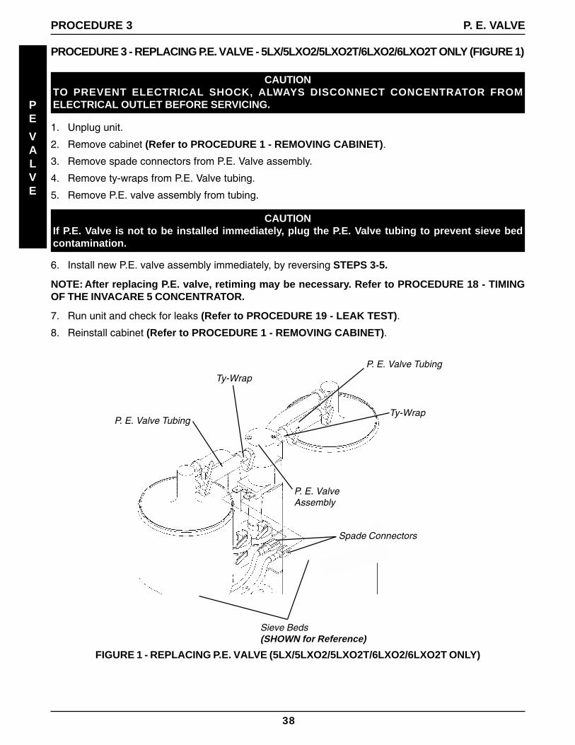
On the 5LX/5LXO2/5LXO2T/6LXO2/6LXO2T, a P.E. or Pressure Equalization valve opens just prior tothe shift of the 4-way valve. This allows highly concentrated oxygen to enter the just exhausted bed fromthe top. This additional pressure allows the bed to start its cycle at a higher pressure. The P.E. valve willclose just after the shift of the 4-way valve.
INSTALLATION/SEQUENCE OF OPERATION
SEQUENCE
OF
OPERATION
12
INSTALLATION / SEQUENCE OF OPERATION, CONTINUEDIf main power is lost, the Battery FreeTM Power Loss Alarm will sound a short "beep", with a long pause,intermittently. All units are equipped with a diagnostic alarm system that signals if the pneumatic pressureor electrical systems malfunction. The Troubleshooting Guide explains the alarm system signals andreasons in detail for your convenience.
The oxygen being produced by the concentrator flows out of the product tank and into the flowmeter.In-line between these components is a tee fitting that directs a small flow of oxygen through a precisionorifice to the oxygen sensor mounted on a printed circuit board.
As the oxygen enters the sensor, it passes through a screen and contacts the sensing disk.
Electric current flowing through a metal film resistor heats the disk in excess of 300O C. Oxygen moleculescontact the electrode of the disk and pick-up extra electrons to become oxygen ions. These oxygen ionsare attracted to the electrode on the bottom of the zirconia disk. Because of the crystal structure of thezirconia, only oxygen ions can pass through. When the oxygen ions reach the bottom electrode, the extraelectrons are released from the oxygen ions and oxygen molecules return to the air. The number ofelectrons is directly related to the oxygen concentration. The electrons travel to the PC board where theyare "counted" and the oxygen concentration "reading" is calculated.
A microprocessor on the P.C. board contains software that interprets the signal being received from thesensor. It compares the signal to clinically acceptable limits that have been selected with the indicatorswitch mounted on the PC board. Signals outside of the clinically acceptable limits generate responses inthe form of lighted LEDs, audible indicators, and/or system shut-down.
Operating Sequence
Once the power switch has been turned ON, the SensO2 circuit will wait 5 minutes for the concentrator tobegin producing clinically acceptable oxygen before activating. No LEDs will illuminate for at least 5minutes.
After 5 minutes, if the oxygen purity exceeds 85% + 2% the GREEN LED will illuminate.
If the oxygen level is not above 85% + 2% after the first 5 minutes, LEDs will remain off. The system willwait for a maximum of 30 minutes from start-up to reach 85% + 2% before activating an alarm. Environ-mental factors such as low voltage, high altitude, or age of the machine will affect the time required toreach 85% + 2%.
If the oxygen level is not above 85% + 2% within the first 30 minutes, the oxygen concentration alarmsequence will activate, depending upon the position of the indicator switch. All units are preset at thefactory at 73% + 3%.
When oxygen concentration is above 85% + 2%, the sensor measures oxygen purity every 10 minutes.If a reading falls below 85% + 2% and the alarm indicator is in the 73% mode or no switch is present, theoxygen sensor measures purity continuously and a yellow LED will illuminate. If the oxygen purity fallsbelow 73% + 3% the RED LED/Alarm/Shut-Down mode will activate. If the selector switch is presentand it is set at 85%, the RED LED/Alarm/Shut-Down mode will activate if the oxygen purity falls below85% + 2%.
NOTE: REFER TO THE REPAIR/REPLACEMENT GUIDE IN THIS MANUAL FOR PROPERREPLACEMENT OR ADJUSTMENT PROCEDURES
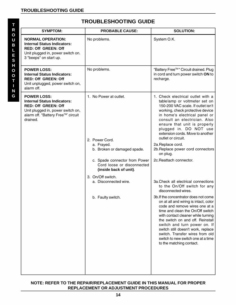
NORMAL OPERATION:Internal Status Indicators:RED: Off GREEN: OffUnit plugged in, power switch on.3 "beeps" on start up.
POWER LOSS:Internal Status Indicators:RED: Off GREEN: OffUnit unplugged, power switch on,alarm off.
No problems.
POWER LOSS:Internal Status Indicators:RED: Off GREEN: OffUnit plugged in, power switch on,alarm off. "Battery FreeTM" circuitdrained.
1. No Power at outlet.
2. Power Cord.a. Frayed.b. Broken or damaged spade.
c. Spade connector from PowerCord loose or disconnected(inside back of unit).
3. On/Off switch.a. Disconnected wire.
b. Faulty switch.
1. Check electrical outlet with atable lamp or voltmeter set on150-200 VAC scale. If outlet isn'tworking, check protective devicein home's electrical panel orconsult an electrician. Alsoensure that unit is properlyplugged in. DO NOT useextension cords. Move to anotheroutlet or circuit.
2a.Replace cord.2b.Replace power cord connectors
on plug.
2c.Reattach connector.
3a.Check all electrical connectionsto the On/Off switch for anydisconnected wires.
3b.If the concentrator does not comeon at all and wiring is intact, colorcode and remove wires one at atime and clean the On/Off switchwith contact cleaner while turningthe switch on and off. Reinstallswitch and turn power on. Ifswitch still doesn't work, replaceswitch. Transfer wires from oldswitch to new switch one at a timeto the matching contact.
No problems. System O.K.
TROUBLESHOOTING GUIDE
TROUBLESHOOTING GUIDE
"Battery FreeTM " Circuit drained. Plugin cord and turn power switch ON torecharge.
15
TROUBLESHOOTING
TROUBLESHOOTING GUIDE
TROUBLESHOOTING GUIDE
SYMPTOM: PROBABLE CAUSE: SOLUTION:
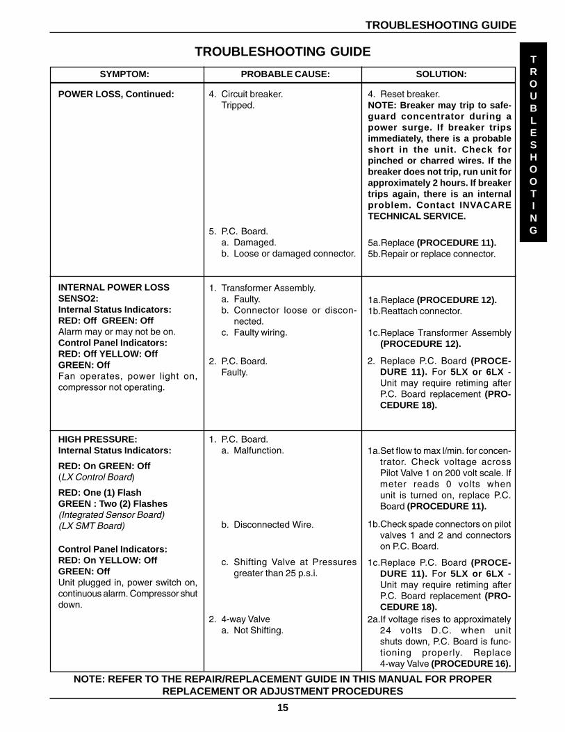
4. Circuit breaker.Tripped.
POWER LOSS, Continued:
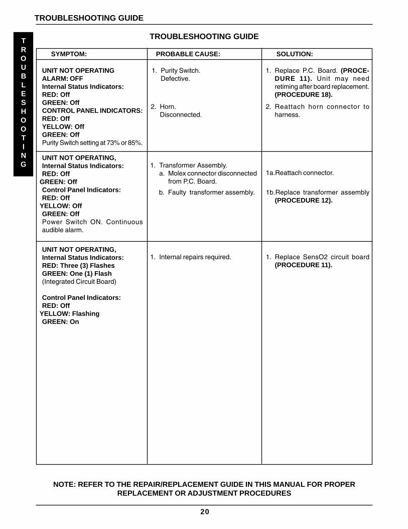
1. Transformer Assembly.a. Faulty.b. Connector loose or discon-
nected.c. Faulty wiring.
2. P.C. Board.Faulty.
INTERNAL POWER LOSSSENSO2:Internal Status Indicators:RED: Off GREEN: OffAlarm may or may not be on.Control Panel Indicators:RED: Off YELLOW: OffGREEN: OffFan operates, power light on,compressor not operating.
1c.Replace Transformer Assembly(PROCEDURE 12).
HIGH PRESSURE:Internal Status Indicators:
RED: On GREEN: Off(LX Control Board)
RED: One (1) FlashGREEN : Two (2) Flashes(Integrated Sensor Board)(LX SMT Board)
Control Panel Indicators:RED: On YELLOW: OffGREEN: OffUnit plugged in, power switch on,continuous alarm. Compressor shutdown.
1. P.C. Board.a. Malfunction. 1a.Set flow to max l/min. for concen-
trator. Check voltage acrossPilot Valve 1 on 200 volt scale. Ifmeter reads 0 volts whenunit is turned on, replace P.C.Board (PROCEDURE 11).
b. Disconnected Wire.
2. 4-way Valvea. Not Shifting.
NOTE: REFER TO THE REPAIR/REPLACEMENT GUIDE IN THIS MANUAL FOR PROPERREPLACEMENT OR ADJUSTMENT PROCEDURES
4. Reset breaker.NOTE: Breaker may trip to safe-guard concentrator during apower surge. If breaker tripsimmediately, there is a probableshort in the unit. Check forpinched or charred wires. If thebreaker does not trip, run unit forapproximately 2 hours. If breakertrips again, there is an internalproblem. Contact INVACARETECHNICAL SERVICE.
5. P.C. Board.a. Damaged.b. Loose or damaged connector.
5a.Replace (PROCEDURE 11).5b.Repair or replace connector.
1a.Replace (PROCEDURE 12).1b.Reattach connector.
2. Replace P.C. Board (PROCE-DURE 11). For 5LX or 6LX -Unit may require retiming afterP.C. Board replacement (PRO-CEDURE 18).
1b.Check spade connectors on pilotvalves 1 and 2 and connectorson P.C. Board.
1c.Replace P.C. Board (PROCE-DURE 11). For 5LX or 6LX -Unit may require retiming afterP.C. Board replacement (PRO-CEDURE 18).
c. Shifting Valve at Pressuresgreater than 25 p.s.i.
2a.If voltage rises to approximately24 volts D.C. when unitshuts down, P.C. Board is func-tioning properly. Replace4-way Valve (PROCEDURE 16).
16
TROUBLESHOOTING GUIDE
SYMPTOM: PROBABLE CAUSE: SOLUTION:
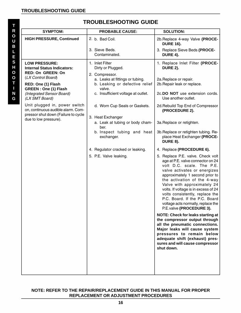
HIGH PRESSURE, Continued
TROUBLESHOOTING
TROUBLESHOOTING GUIDE
2.
NOTE: REFER TO THE REPAIR/REPLACEMENT GUIDE IN THIS MANUAL FOR PROPERREPLACEMENT OR ADJUSTMENT PROCEDURES
2b.Replace 4-way Valve (PROCE-DURE 16).
b. Bad Coil.
3. Replace Sieve Beds (PROCE-DURE 4).
3. Sieve Beds.Contaminated.
1. Inlet FilterDirty or Plugged.
2. Compressor.a. Leaks at fittings or tubing.b. Leaking or defective relief
valve.c. Insufficient voltage at outlet.
d. Worn Cup Seals or Gaskets.
1. Replace Inlet Filter (PROCE-DURE 2).
2a.Replace or repair.2b.Repair leak or replace.
2c.DO NOT use extension cords.Use another outlet.
2d.Rebuild Top End of Compressor(PROCEDURE 2).
3. Heat Exchangera. Leak at tubing or body cham-
ber.b. Inspect tubing and heat
exchanger.
3a.Replace or retighten.
3b.Replace or retighten tubing. Re-place Heat Exchanger (PROCE-DURE 8).
LOW PRESSURE:Internal Status Indicators:RED: On GREEN: On(LX Control Board)
RED: One (1) FlashGREEN : One (1) Flash(Integrated Sensor Board)(LX SMT Board)
Unit plugged in, power switchon, continuous audible alarm. Com-pressor shut down (Failure to cycledue to low pressure).
4. Replace (PROCEDURE 6).4. Regulator cracked or leaking.
5. P.E. Valve leaking. 5. Replace P.E. valve. Check voltage at P.E. valve connector on 24volt D.C. scale. The P.E.valve activates or energizesapproximately 1 second prior tothe activation of the 4-wayValve with approximately 24volts. If voltage is in excess of 24volts consistently, replace theP.C. Board. If the P.C. Boardvoltage acts normally, replace theP.E.valve (PROCEDURE 3).
NOTE: Check for leaks starting atthe compressor output throughall the pneumatic connections.Major leaks will cause systempressures to remain belowadequate shift (exhaust) pres-sures and will cause compressorshut down.
17
TROUBLESHOOTING GUIDE
SYMPTOM: PROBABLE CAUSE: SOLUTION:TROUBLESHOOTING
TROUBLESHOOTING GUIDE
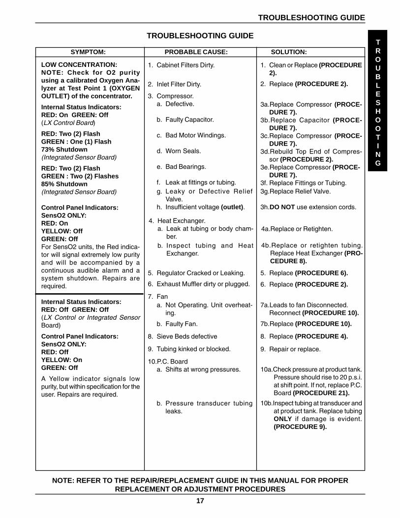
LOW CONCENTRATION:NOTE: Check for O2 purityusing a calibrated Oxygen Ana-lyzer at Test Point 1 (OXYGENOUTLET) of the concentrator.
Internal Status Indicators:RED: On GREEN: Off(LX Control Board)
RED: Two (2) FlashGREEN : One (1) Flash73% Shutdown(Integrated Sensor Board)
RED: Two (2) FlashGREEN : Two (2) Flashes85% Shutdown(Integrated Sensor Board)
Control Panel Indicators:SensO2 ONLY:RED: OnYELLOW: OffGREEN: OffFor SensO2 units, the Red indica-tor will signal extremely low purityand will be accompanied by acontinuous audible alarm and asystem shutdown. Repairs arerequired.
Internal Status Indicators:RED: Off GREEN: Off(LX Control or Integrated SensorBoard)
Control Panel Indicators:SensO2 ONLY:RED: OffYELLOW: OnGREEN: Off
A Yellow indicator signals lowpurity, but within specification for theuser. Repairs are required.
NOTE: REFER TO THE REPAIR/REPLACEMENT GUIDE IN THIS MANUAL FOR PROPERREPLACEMENT OR ADJUSTMENT PROCEDURES
1. Clean or Replace (PROCEDURE2).
2. Replace (PROCEDURE 2).
1. Cabinet Filters Dirty.
3. Compressor.a. Defective.
b. Faulty Capacitor.
c. Bad Motor Windings.
d. Worn Seals.
e. Bad Bearings.
f. Leak at fittings or tubing.
3a.Replace Compressor (PROCE-DURE 7).
3b.Replace Capacitor (PROCE-DURE 7).
3c.Replace Compressor (PROCE-DURE 7).
3d.Rebuild Top End of Compres-sor (PROCEDURE 2).
3e.Replace Compressor (PROCE-DURE 7).
3f. Replace Fittings or Tubing.
2. Inlet Filter Dirty.
4. Heat Exchanger.a. Leak at tubing or body cham-
ber.4a.Replace or Retighten.
4b.Replace or retighten tubing.Replace Heat Exchanger (PRO-CEDURE 8).
b. Inspect tubing and HeatExchanger.
7a.Leads to fan Disconnected.Reconnect (PROCEDURE 10).
7b.Replace (PROCEDURE 10).
8. Replace (PROCEDURE 4).
9. Repair or replace.
10a.Check pressure at product tank.Pressure should rise to 20 p.s.i.at shift point. If not, replace P.C.Board (PROCEDURE 21).
10b.Inspect tubing at transducer andat product tank. Replace tubingONLY if damage is evident.(PROCEDURE 9).
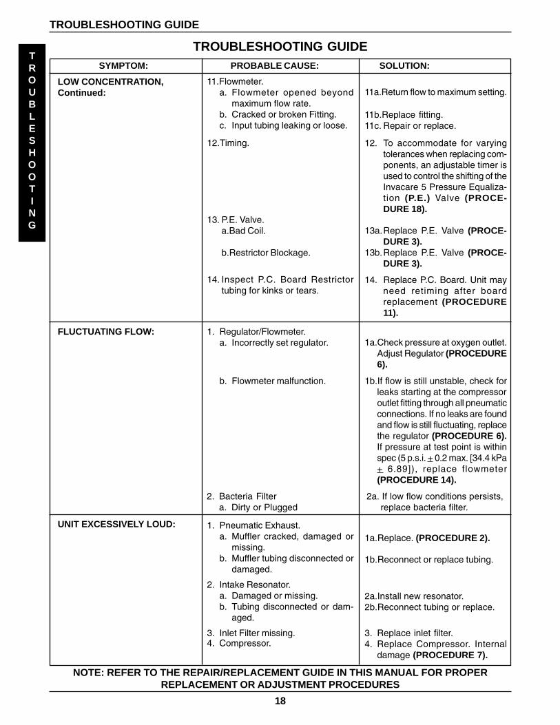
maximum flow rate.b. Cracked or broken Fitting.c. Input tubing leaking or loose.
12.Timing.
TROUBLESHOOTING
TROUBLESHOOTING GUIDE
14. Replace P.C. Board. Unit mayneed retiming after boardreplacement (PROCEDURE11).
13. P.E. Valve.a.Bad Coil.
b.Restrictor Blockage.
14. Inspect P.C. Board Restrictortubing for kinks or tears.
FLUCTUATING FLOW:
NOTE: REFER TO THE REPAIR/REPLACEMENT GUIDE IN THIS MANUAL FOR PROPERREPLACEMENT OR ADJUSTMENT PROCEDURES
1. Regulator/Flowmeter.a. Incorrectly set regulator.
b. Flowmeter malfunction.
UNIT EXCESSIVELY LOUD:
1a.Replace. (PROCEDURE 2).
2a.Install new resonator.2b.Reconnect tubing or replace.
1. Pneumatic Exhaust.a. Muffler cracked, damaged or
missing.b. Muffler tubing disconnected or
damaged.
2. Intake Resonator.a. Damaged or missing.b. Tubing disconnected or dam-
aged.
3. Inlet Filter missing.4. Compressor.
12. To accommodate for varyingtolerances when replacing com-ponents, an adjustable timer isused to control the shifting of theInvacare 5 Pressure Equaliza-tion (P.E.) Valve (PROCE-DURE 18).
13a.Replace P.E. Valve (PROCE-DURE 3).
13b.Replace P.E. Valve (PROCE-DURE 3).
1a.Check pressure at oxygen outlet.Adjust Regulator (PROCEDURE6).
1b.If flow is still unstable, check forleaks starting at the compressoroutlet fitting through all pneumaticconnections. If no leaks are foundand flow is still fluctuating, replacethe regulator (PROCEDURE 6).If pressure at test point is withinspec (5 p.s.i. + 0.2 max. [34.4 kPa+ 6.89]), replace flowmeter(PROCEDURE 14).
2a. If low flow conditions persists, replace bacteria filter.
19
TROUBLESHOOTING GUIDE
SYMPTOM: PROBABLE CAUSE: SOLUTION:
TROUBLESHOOTING
TROUBLESHOOTING GUIDE
NOTE: REFER TO THE REPAIR/REPLACEMENT GUIDE IN THIS MANUAL FOR PROPERREPLACEMENT OR ADJUSTMENT PROCEDURES
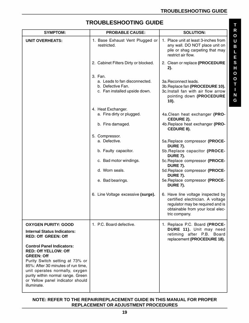
UNIT OVERHEATS: 1. Base Exhaust Vent Plugged orrestricted.
1. Place unit at least 3-inches fromany wall. DO NOT place unit onpile or shag carpeting that mayrestrict air flow.
2. Clean or replace (PROCEDURE2).
2. Cabinet Filters Dirty or blocked.
3a.Reconnect leads.3b.Replace fan (PROCEDURE 10).3c.Install fan with air flow arrow
pointing down (PROCEDURE10).
4a.Clean heat exchanger (PRO-CEDURE 2).
4b.Replace heat exchanger (PRO-CEDURE 8).
3. Fan.a. Leads to fan disconnected.b. Defective Fan.c. Fan installed upside down.
4. Heat Exchanger.a. Fins dirty or plugged.
b. Fins damaged.
5. Compressor.a. Defective.
b. Faulty capacitor.
c. Bad motor windings.
d. Worn seals.
e. Bad bearings.
6. Line Voltage excessive (surge). 6. Have line voltage inspected bycertified electrician. A voltageregulator may be required and isobtainable from your local elec-tric company.
5a.Replace compressor (PROCE-DURE 7).
5b.Replace capacitor (PROCE-DURE 7).
5c.Replace compressor (PROCE-DURE 7).
5d.Replace compressor (PROCE-DURE 7).
5e.Replace compressor (PROCE-DURE 7).
OXYGEN PURITY: GOOD
Internal Status Indicators:RED: Off GREEN: Off
Control Panel Indicators:RED: Off YELLOW: OffGREEN: OffPurity Switch setting at 73% or85%: After 30 minutes of run time,unit operates normally, oxygenpurity within normal range. Greenor Yellow panel indicator shouldilluminate.
1. P.C. Board defective. 1. Replace P.C. Board (PROCE-DURE 11). Unit may needretiming after P.B. Boardreplacement (PROCEDURE 18).
20
TROUBLESHOOTING GUIDETROUBLESHOOTING
UNIT NOT OPERATINGALARM: OFFInternal Status Indicators:RED: OffGREEN: OffCONTROL PANEL INDICATORS:RED: OffYELLOW: OffGREEN: OffPurity Switch setting at 73% or 85%.
TROUBLESHOOTING GUIDE
NOTE: REFER TO THE REPAIR/REPLACEMENT GUIDE IN THIS MANUAL FOR PROPERREPLACEMENT OR ADJUSTMENT PROCEDURES
1. Replace P.C. Board. (PROCE-DURE 11). Unit may needretiming after board replacement.(PROCEDURE 18).
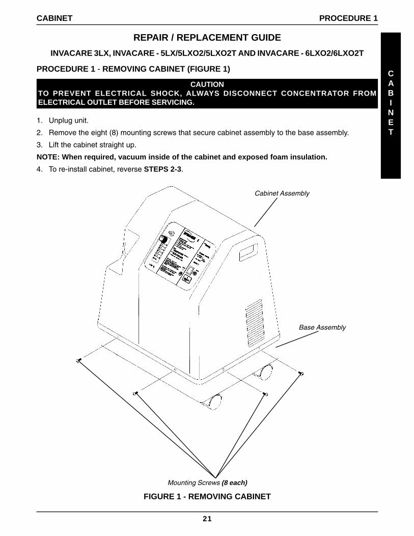
2. Remove the eight (8) mounting screws that secure cabinet assembly to the base assembly.
3. Lift the cabinet straight up.
NOTE: When required, vacuum inside of the cabinet and exposed foam insulation.
4. To re-install cabinet, reverse STEPS 2-3.
Cabinet Assembly
Mounting Screws (8 each)
FIGURE 1 - REMOVING CABINET
CABINET PROCEDURE 1
Base Assembly
22
PROCEDURE 2 - PREVENTIVE MAINTENANCE
PROCEDURE 2 PREVENTIVE MAINTENANCE
CAUTIONTO PREVENT ELECTRICAL SHOCK, ALWAYSDISCONNECT CONCENTRATOR FROM ELEC-TRICAL OUTLET BEFORE SERVICING.
NOTE: The Invacare Concentrators are specifi-cally designed to minimize routine preventivemaintenance at intervals of once per year. Inplaces with high dust or soot levels, mainte-nance may need to be performed more often.The following must be performed at a minimumof one (1) year in service to assure years of ad-ditional reliability (Refer to TROUBLESHOOT-ING GUIDE for plugged filter symptoms). Onlyauthorized or factory-trained personnel shouldperform preventive maintenance on the concen-trator. Power should be disconnected before be-ginning preventive maintenance on the Invacareconcentrator.
Cabinet Filters (FIGURE 1)
1. Clean or replace gross particle (cabinet) filterson both side of the cabinet.
FIGURE 1 - CABINET FILTERS
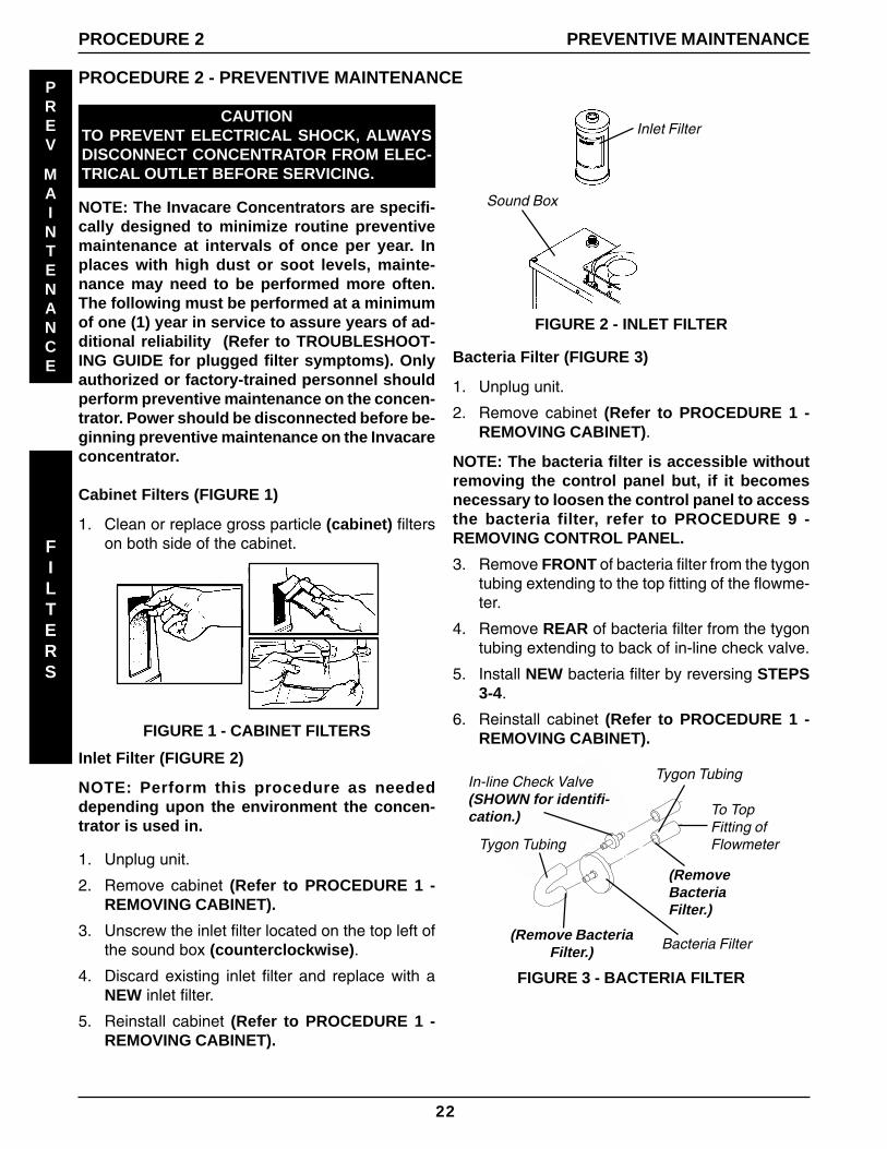
Inlet Filter
Sound Box
Inlet Filter (FIGURE 2)
NOTE: Perform this procedure as neededdepending upon the environment the concen-trator is used in.
1. Unplug unit.
2. Remove cabinet (Refer to PROCEDURE 1 -REMOVING CABINET).
3. Unscrew the inlet filter located on the top left ofthe sound box (counterclockwise).
4. Discard existing inlet filter and replace with aNEW inlet filter.
5. Reinstall cabinet (Refer to PROCEDURE 1 -REMOVING CABINET).
FIGURE 3 - BACTERIA FILTER
Bacteria Filter (FIGURE 3)
1. Unplug unit.
2. Remove cabinet (Refer to PROCEDURE 1 -REMOVING CABINET).
NOTE: The bacteria filter is accessible withoutremoving the control panel but, if it becomesnecessary to loosen the control panel to accessthe bacteria filter, refer to PROCEDURE 9 -REMOVING CONTROL PANEL.
3. Remove FRONT of bacteria filter from the tygontubing extending to the top fitting of the flowme-ter.
4. Remove REAR of bacteria filter from the tygontubing extending to back of in-line check valve.
5. Install NEW bacteria filter by reversing STEPS3-4.
6. Reinstall cabinet (Refer to PROCEDURE 1 -REMOVING CABINET).
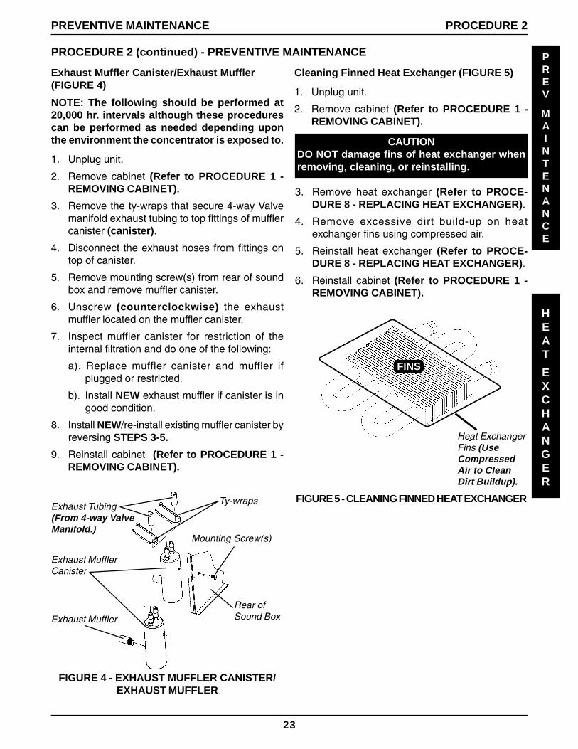
NOTE: The following should be performed at20,000 hr. intervals although these procedurescan be performed as needed depending uponthe environment the concentrator is exposed to.
1. Unplug unit.
2. Remove cabinet (Refer to PROCEDURE 1 -REMOVING CABINET).
3. Remove the ty-wraps that secure 4-way Valvemanifold exhaust tubing to top fittings of mufflercanister (canister).
4. Disconnect the exhaust hoses from fittings ontop of canister.
5. Remove mounting screw(s) from rear of soundbox and remove muffler canister.
6. Unscrew (counterclockwise) the exhaustmuffler located on the muffler canister.
7. Inspect muffler canister for restriction of theinternal filtration and do one of the following:
a). Replace muffler canister and muffler ifplugged or restricted.
b). Install NEW exhaust muffler if canister is ingood condition.
6. Reinstall cabinet (Refer to PROCEDURE 1 -REMOVING CABINET).
FINS
Heat ExchangerFins (UseCompressedAir to CleanDirt Buildup).
FIGURE 5 - CLEANING FINNED HEAT EXCHANGER
24
CAUTIONTO PREVENT ELECTRICAL SHOCK, ALWAYS DIS-CONNECT CONCENTRATOR FROM ELECTRICALOUTLET BEFORE SERVICING.
PREV
MAINTENANCE
3
LTR
COMP
REBUILD
PROCEDURE 2 PREVENTIVE MAINTENANCE
PROCEDURE 2 - PREVENTIVE MAINTENANCE (continued)
*NOTE: This kit is designed for rebuilding the Tho-mas Model 2638 or 2618. These compressors usethis rebuild kit. The serial number is located on thefront of the compressor. If the serial number doesnot begin in this way, this kit will not work.
The 3-Liter Thomas 2638 or 2618 CompressorRebuild Kit contains the following:
1. Two (2) Connecting (Piston) Rod Assemblies.2. Two (2) Connecting Rod Screws.3. Two (2) Aluminum Piston Sleeves.4. Four (4) Valves.5. Two (2) Valve Restraints.6. Two (2) Head Gaskets.7. Two (2) Valve Plate Gasket.8. Two (2) Connecting Rod Screw.9. Twelve (12) Head Mounting Screws.10. Four (4) Valve Screws.11. Four (4) Connector (Crossover) Tube "O" Rings.12. Hernon # 846 Lubricant.13. Hernon # 423 Threadlocker.
Tools Required:
One (1) 1/8 and 5/32-inch Allen Wrench attachment.Inch Pound Scale Torque Wrench.
One (1) Common (Flathead) Screwdriver.One (1) Small Common (Flathead) Screwdriver.One (1) Phillips Head Screwdriver.
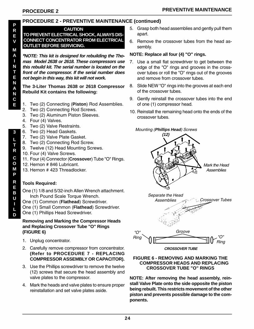
Removing and Marking the Compressor Headsand Replacing Crossover Tube "O" Rings(FIGURE 6)
1. Unplug concentrator.
2. Carefully remove compressor from concentrator.(Refer to PROCEDURE 7 - REPLACINGCOMPRESSOR ASSEMBLY OR CAPACITOR).
3. Use the Phillips screwdriver to remove the twelve(12) screws that secure the head assembly andvalve plates to the compressor.
4. Mark the heads and valve plates to ensure properreinstallation and set valve plates aside.
5. Grasp both head assemblies and gently pull themapart.
6. Remove the crossover tubes from the head as-sembly.
NOTE: Replace all four (4) "O" rings.
7. Use a small flat screwdriver to get between theedge of the "O" rings and grooves in the cross-over tubes or roll the "O" rings out of the groovesand remove from crossover tubes.
8. Slide NEW "O" rings into the grooves at each endof the crossover tubes.
9. Gently reinstall the crossover tubes into the endof one (1) compressor head.
10. Reinstall the remaining head onto the ends of thecrossover tubes.
Mounting (Phillips Head) Screws(12)
Mark the HeadAssemblies
Separate the HeadAssemblies Crossover Tubes
FIGURE 6 - REMOVING AND MARKING THECOMPRESSOR HEADS AND REPLACING
CROSSOVER TUBE "O" RINGS
NOTE: After removing the head assembly, rein-stall Valve Plate onto the side opposite the pistonbeing rebuilt. This restricts movement of the otherpiston and prevents possible damage to the com-ponents.
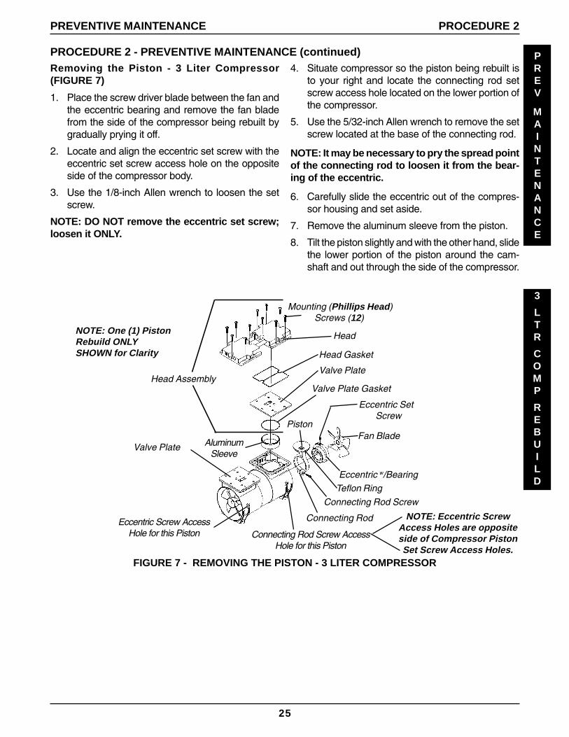
1. Place the screw driver blade between the fan andthe eccentric bearing and remove the fan bladefrom the side of the compressor being rebuilt bygradually prying it off.
2. Locate and align the eccentric set screw with theeccentric set screw access hole on the oppositeside of the compressor body.
3. Use the 1/8-inch Allen wrench to loosen the setscrew.
NOTE: DO NOT remove the eccentric set screw;loosen it ONLY.
4. Situate compressor so the piston being rebuilt isto your right and locate the connecting rod setscrew access hole located on the lower portion ofthe compressor.
5. Use the 5/32-inch Allen wrench to remove the setscrew located at the base of the connecting rod.
NOTE: It may be necessary to pry the spread pointof the connecting rod to loosen it from the bear-ing of the eccentric.
6. Carefully slide the eccentric out of the compres-sor housing and set aside.
7. Remove the aluminum sleeve from the piston.
8. Tilt the piston slightly and with the other hand, slidethe lower portion of the piston around the cam-shaft and out through the side of the compressor.
FIGURE 7 - REMOVING THE PISTON - 3 LITER COMPRESSOR
Head Gasket
Valve Plate
Eccentric SetScrew
Mounting (Phillips Head)Screws (12)
Head
PistonFan Blade
Teflon RingConnecting Rod Screw
Eccentric w/Bearing
Connecting Rod
Valve Plate GasketHead Assembly
AluminumSleeve
Eccentric Screw AccessHole for this Piston
Valve Plate
Connecting Rod Screw AccessHole for this Piston
NOTE: Eccentric ScrewAccess Holes are oppositeside of Compressor PistonSet Screw Access Holes.
NOTE: One (1) PistonRebuild ONLYSHOWN for Clarity
26
PREV
MAINTENANCE
3
LTR
COMP
REBUILD
PROCEDURE 2 PREVENTIVE MAINTENANCE
PROCEDURE 2 - PREVENTIVE MAINTENANCE (continued)Installing the New Piston (FIGURE 8)
WARNINGDO NOT lubricate or use oil on any moving parts.The compressor eccentric uses a precision sealedbearing.
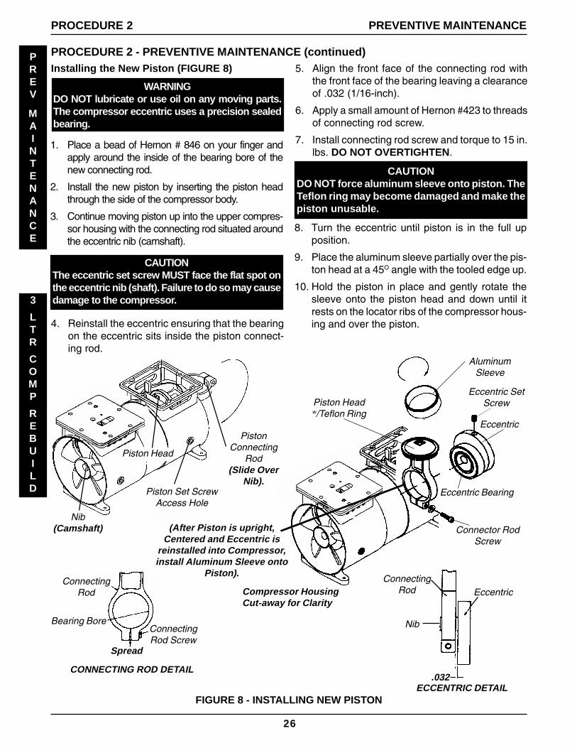
1. Place a bead of Hernon # 846 on your finger andapply around the inside of the bearing bore of thenew connecting rod.
2. Install the new piston by inserting the piston headthrough the side of the compressor body.
3. Continue moving piston up into the upper compres-sor housing with the connecting rod situated aroundthe eccentric nib (camshaft).
CAUTIONThe eccentric set screw MUST face the flat spot onthe eccentric nib (shaft). Failure to do so may causedamage to the compressor.
4. Reinstall the eccentric ensuring that the bearingon the eccentric sits inside the piston connect-ing rod.
5. Align the front face of the connecting rod withthe front face of the bearing leaving a clearanceof .032 (1/16-inch).
6. Apply a small amount of Hernon #423 to threadsof connecting rod screw.
7. Install connecting rod screw and torque to 15 in.lbs. DO NOT OVERTIGHTEN.
CAUTIONDO NOT force aluminum sleeve onto piston. TheTeflon ring may become damaged and make thepiston unusable.
8. Turn the eccentric until piston is in the full upposition.
9. Place the aluminum sleeve partially over the pis-ton head at a 45O angle with the tooled edge up.
10. Hold the piston in place and gently rotate thesleeve onto the piston head and down until itrests on the locator ribs of the compressor hous-ing and over the piston.
Spread
ConnectingRod Screw
Bearing Bore
ConnectingRod
Piston Headw/Teflon Ring
ConnectingRod Eccentric
Nib
.032ECCENTRIC DETAIL
CONNECTING ROD DETAIL
AluminumSleeve
Eccentric SetScrew
Eccentric Bearing
Eccentric
Connector RodScrew
Compressor HousingCut-away for Clarity
FIGURE 8 - INSTALLING NEW PISTON
(After Piston is upright,Centered and Eccentric is
reinstalled into Compressor,install Aluminum Sleeve onto
Piston).
PistonConnecting
Rod(Slide Over
Nib).
Nib(Camshaft)
Piston Set Screw Access Hole
Piston Head
27
PREV
MAINTENANCE
3
LTR
COMP
REBUILD
PROCEDURE 2 - PREVENTIVE MAINTENANCE (continued)
PREVENTIVE MAINTENANCE
Alignment of the Piston (FIGURE 8)
1. Hold sleeve down with one hand and slowly turneccentric with the other.
2. As the piston travels up and down, the connectingrod will rock from front to back in normal opera-tion.
3. If connecting rod rocks side to side, the rod is mis-aligned on the eccentric bearing.
4. If this is evident, loosen set screw and repeatSTEPS 3-8 for INSTALLING THE PISTON.
5. If connecting rod cannot be properly aligned, con-tact Invacare Technical Service.
6. Twist the aluminum sleeve back up onto the pis-ton until sleeve is approximately centered on theteflon ring of the piston.
7. With the aluminum sleeve firmly seated onto lo-cator ribs, set the individual valve plate from thatside of the compressor onto the aluminum sleeveand position it until the six (6) holes in the valveplate line up with the six (6) holes in the top of thecompressor housing. This aligns the piston assem-bly.
8. Securely tighten the connecting rod screw againstthe flat spot on the nib (camshaft) (FIGURE 3).
CAUTIONEnsure that eccentric set screw is aligned withthe flat spot on the cam shaft. Failure to do somay result in damage to compressor or possibleinjury.
9. Reinstall the fan blade securely over the nib infront of the eccentric (FIGURE 3).
10. Temporarily reinstall the valve plate for the pistonjust replaced to simplify installation of the otherpiston.
11. Begin at FIGURE 2 for installation of the new pis-ton on the opposite side of the compressor.
PROCEDURE 2
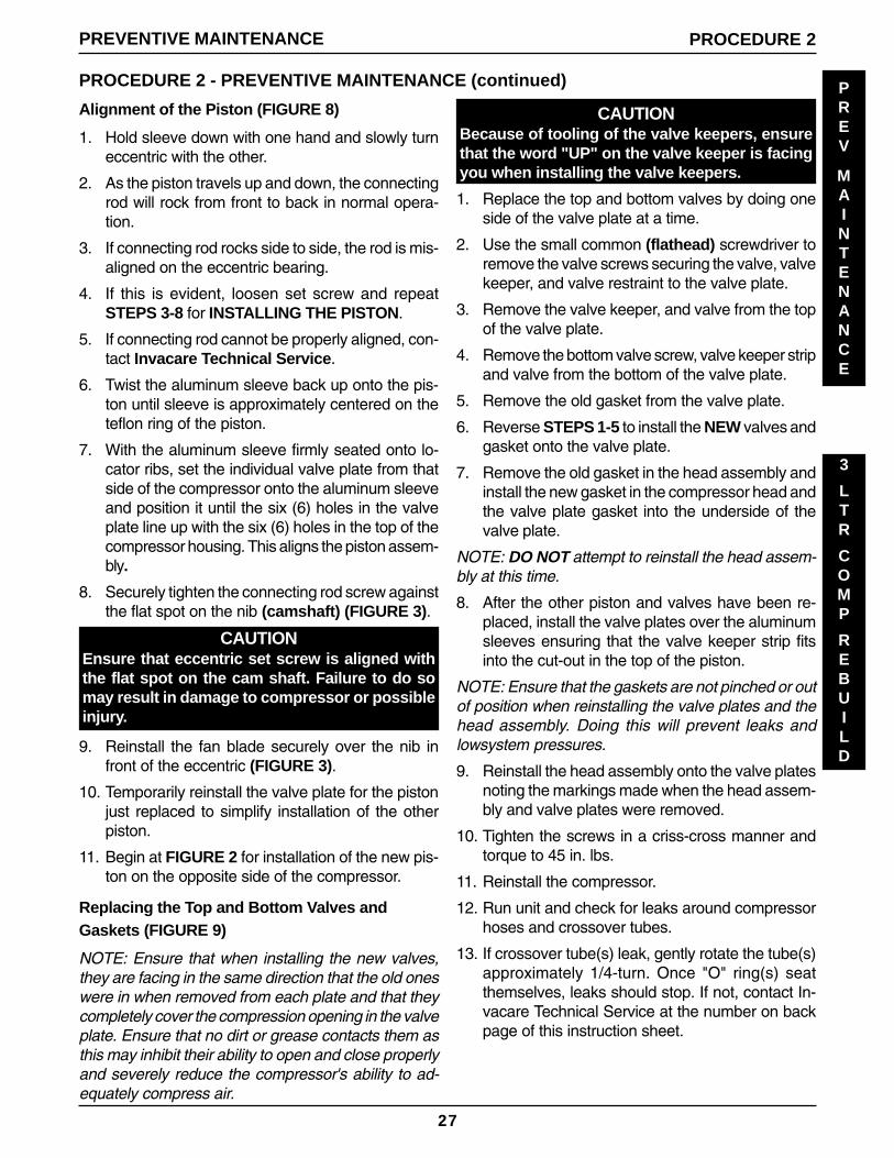
Replacing the Top and Bottom Valves andGaskets (FIGURE 9)
NOTE: Ensure that when installing the new valves,they are facing in the same direction that the old oneswere in when removed from each plate and that theycompletely cover the compression opening in the valveplate. Ensure that no dirt or grease contacts them asthis may inhibit their ability to open and close properlyand severely reduce the compressor's ability to ad-equately compress air.
CAUTIONBecause of tooling of the valve keepers, ensurethat the word "UP" on the valve keeper is facingyou when installing the valve keepers.
1. Replace the top and bottom valves by doing oneside of the valve plate at a time.
2. Use the small common (flathead) screwdriver toremove the valve screws securing the valve, valvekeeper, and valve restraint to the valve plate.
3. Remove the valve keeper, and valve from the topof the valve plate.
4. Remove the bottom valve screw, valve keeper stripand valve from the bottom of the valve plate.
5. Remove the old gasket from the valve plate.
6. Reverse STEPS 1-5 to install the NEW valves andgasket onto the valve plate.
7. Remove the old gasket in the head assembly andinstall the new gasket in the compressor head andthe valve plate gasket into the underside of thevalve plate.
NOTE: DO NOT attempt to reinstall the head assem-bly at this time.
8. After the other piston and valves have been re-placed, install the valve plates over the aluminumsleeves ensuring that the valve keeper strip fitsinto the cut-out in the top of the piston.
NOTE: Ensure that the gaskets are not pinched or outof position when reinstalling the valve plates and thehead assembly. Doing this will prevent leaks andlowsystem pressures.
9. Reinstall the head assembly onto the valve platesnoting the markings made when the head assem-bly and valve plates were removed.
10. Tighten the screws in a criss-cross manner andtorque to 45 in. lbs.
11. Reinstall the compressor.
12. Run unit and check for leaks around compressorhoses and crossover tubes.
13. If crossover tube(s) leak, gently rotate the tube(s)approximately 1/4-turn. Once "O" ring(s) seatthemselves, leaks should stop. If not, contact In-vacare Technical Service at the number on backpage of this instruction sheet.
28
PREV
MAINTENANCE
3
LTR
COMP
REBUILD
PROCEDURE 2 PREVENTIVE MAINTENANCE
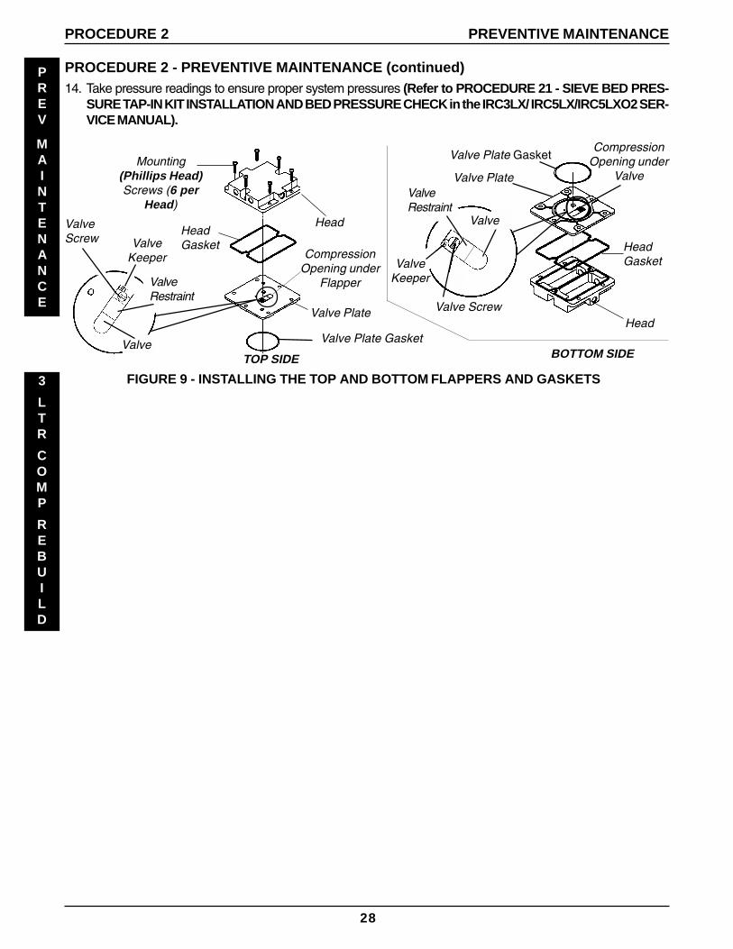
PROCEDURE 2 - PREVENTIVE MAINTENANCE (continued)14. Take pressure readings to ensure proper system pressures (Refer to PROCEDURE 21 - SIEVE BED PRES-
SURE TAP-IN KIT INSTALLATION AND BED PRESSURE CHECK in the IRC3LX/ IRC5LX/IRC5LXO2 SER-VICE MANUAL).
CompressionOpening under
Flapper
Valve Plate
Head
Valve Plate Gasket
Valve Screw
Valve Plate Gasket
BOTTOM SIDE
Valve PlateMounting
(Phillips Head)Screws (6 per
Head)
CompressionOpening under
Valve
ValveKeeper
ValveScrew
ValveTOP SIDE
ValveKeeper
Valve
HeadGasket
Head
FIGURE 9 - INSTALLING THE TOP AND BOTTOM FLAPPERS AND GASKETS
HeadGasket
ValveRestraint
ValveRestraint
29
PREV
MAINTENANCE
5
LTR
COMP
REBUILD
PROCEDURE 2 - PREVENTIVE MAINTENANCE (continued)
PREVENTIVE MAINTENANCE PROCEDURE 2
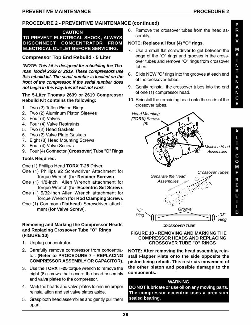
6. Remove the crossover tubes from the head as-sembly.
NOTE: Replace all four (4) "O" rings.
7. Use a small flat screwdriver to get between theedge of the "O" rings and grooves in the cross-over tubes and remove "O" rings from crossovertubes.
8. Slide NEW "O" rings into the grooves at each endof the crossover tubes.
9. Gently reinstall the crossover tubes into the endof one (1) compressor head.
10. Reinstall the remaining head onto the ends of thecrossover tubes.
CAUTIONTO PREVENT ELECTRICAL SHOCK, ALWAYSDISCONNECT CONCENTRATOR FROMELECTRICAL OUTLET BEFORE SERVICING.
Compressor Top End Rebuild - 5 Liter
*NOTE: This kit is designed for rebuilding the Tho-mas Model 2639 or 2619. These compressors usethis rebuild kit. The serial number is located on thefront of the compressor. If the serial number doesnot begin in this way, this kit will not work.
The 5-Liter Thomas 2639 or 2619 CompressorRebuild Kit contains the following:
1. Two (2) Teflon Piston Rings2. Two (2) Aluminum Piston Sleeves3. Four (4) Valves4. Four (4) Valve Restraints5. Two (2) Head Gaskets6. Two (2) Valve Plate Gaskets7. Eight (8) Head Mounting Screws8. Four (4) Valve Screws9. Four (4) Connector (Crossover) Tube "O" Rings
Tools Required:
One (1) Phillips Head TORX T-25 Driver.One (1) Phillips #2 Screwdriver Attachment for
Torque Wrench (for Retainer Screws).One (1) 1/8-inch Allen Wrench attachment for
Torque Wrench (for Eccentric Set Screw).One (1) 5/32-inch Allen Wrench attachment for
Torque Wrench (for Rod Clamping Screw).One (1) Common (Flathead) Screwdriver attach-
ment (for Valve Screw).
Removing and Marking the Compressor Headsand Replacing Crossover Tube "O" Rings(FIGURE 10)
1. Unplug concentrator.
2. Carefully remove compressor from concentra-tor. (Refer to PROCEDURE 7 - REPLACINGCOMPRESSOR ASSEMBLY OR CAPACITOR).
3. Use the TORX T-25 torque wrench to remove theeight (8) screws that secure the head assemblyand valve plates to the compressor.
4. Mark the heads and valve plates to ensure properreinstallation and set valve plates aside.
5. Grasp both head assemblies and gently pull themapart.
Head Mounting(TORX) Screws
(8)
Mark the HeadAssemblies
Groove"O"Ring "O"
Ring
Separate the HeadAssemblies
Crossover Tubes
CROSSOVER TUBE
FIGURE 10 - REMOVING AND MARKING THECOMPRESSOR HEADS AND REPLACING
CROSSOVER TUBE "O" RINGS
NOTE: After removing the head assembly, rein-stall Flapper Plate onto the side opposite thepiston being rebuilt. This restricts movement ofthe other piston and possible damage to thecomponents.
WARNINGDO NOT lubricate or use oil on any moving parts.The compressor eccentric uses a precisionsealed bearing.
30
PREV
MAINTENANCE
5
LTR
COMP
REBUILD
PROCEDURE 2 - PREVENTIVE MAINTENANCE (continued)
PROCEDURE 2 PREVENTIVE MAINTENANCE
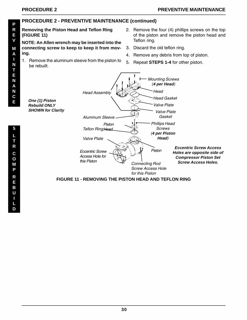
Removing the Piston Head and Teflon Ring(FIGURE 11)
NOTE: An Allen wrench may be inserted into theconnecting screw to keep to keep it from mov-ing.
1. Remove the aluminum sleeve from the piston tobe rebuilt.
2. Remove the four (4) phillips screws on the topof the piston and remove the piston head andTeflon ring.
3. Discard the old teflon ring.
4. Remove any debris from top of piston.
5. Repeat STEPS 1-4 for other piston.
Head
Head Gasket
Valve Plate
Valve PlateGasket
Mounting Screws(4 per Head)
Phillips HeadScrews
(4 per PistonHead)
Aluminum Sleeve
Connecting RodScrew Access Holefor this Piston
Teflon Ring
Valve Plate
Eccentric ScrewAccess Hole forthis Piston
Head Assembly
PistonEccentric Screw Access
Holes are opposite side ofCompressor Piston SetScrew Access Holes.
One (1) PistonRebuild ONLYSHOWN for Clarity
FIGURE 11 - REMOVING THE PISTON HEAD AND TEFLON RING
PistonHead
31
PREV
MAINTENANCE
5
LTR
COMP
REBUILD
PROCEDURE 2 - PREVENTIVE MAINTENANCE (continued)
PREVENTIVE MAINTENANCE PROCEDURE 2
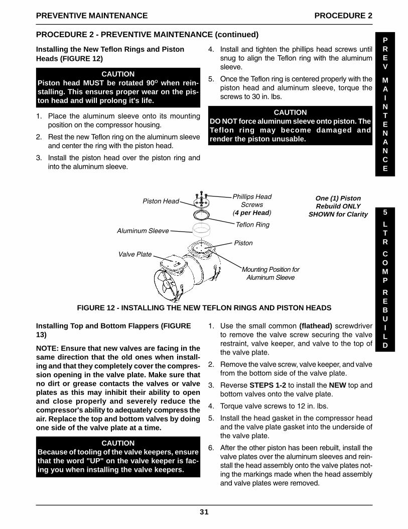
Installing the New Teflon Rings and PistonHeads (FIGURE 12)
4. Install and tighten the phillips head screws untilsnug to align the Teflon ring with the aluminumsleeve.
5. Once the Teflon ring is centered properly with thepiston head and aluminum sleeve, torque thescrews to 30 in. lbs.
CAUTIONPiston head MUST be rotated 90O when rein-stalling. This ensures proper wear on the pis-ton head and will prolong it's life.
1. Place the aluminum sleeve onto its mountingposition on the compressor housing.
2. Rest the new Teflon ring on the aluminum sleeveand center the ring with the piston head.
3. Install the piston head over the piston ring andinto the aluminum sleeve.
One (1) PistonRebuild ONLY
SHOWN for Clarity
Phillips HeadScrews
(4 per Head)
Piston
Teflon RingAluminum Sleeve
Piston Head
Valve Plate
FIGURE 12 - INSTALLING THE NEW TEFLON RINGS AND PISTON HEADS
Mounting Position forAluminum Sleeve
CAUTIONDO NOT force aluminum sleeve onto piston. TheTeflon ring may become damaged andrender the piston unusable.
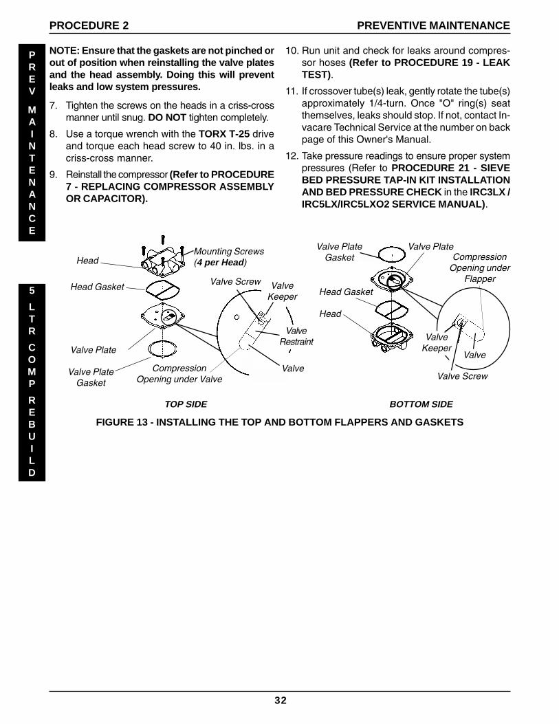
Installing Top and Bottom Flappers (FIGURE13)
NOTE: Ensure that new valves are facing in thesame direction that the old ones when install-ing and that they completely cover the compres-sion opening in the valve plate. Make sure thatno dirt or grease contacts the valves or valveplates as this may inhibit their ability to openand close properly and severely reduce thecompressor's ability to adequately compress theair. Replace the top and bottom valves by doingone side of the valve plate at a time.
CAUTIONBecause of tooling of the valve keepers, ensurethat the word "UP" on the valve keeper is fac-ing you when installing the valve keepers.
1. Use the small common (flathead) screwdriverto remove the valve screw securing the valverestraint, valve keeper, and valve to the top ofthe valve plate.
2. Remove the valve screw, valve keeper, and valvefrom the bottom side of the valve plate.
3. Reverse STEPS 1-2 to install the NEW top andbottom valves onto the valve plate.
4. Torque valve screws to 12 in. lbs.
5. Install the head gasket in the compressor headand the valve plate gasket into the underside ofthe valve plate.
6. After the other piston has been rebuilt, install thevalve plates over the aluminum sleeves and rein-stall the head assembly onto the valve plates not-ing the markings made when the head assemblyand valve plates were removed.
32
PREV
MAINTENANCE
5
LTR
COMP
REBUILD
PROCEDURE 2 PREVENTIVE MAINTENANCE
NOTE: Ensure that the gaskets are not pinched orout of position when reinstalling the valve platesand the head assembly. Doing this will preventleaks and low system pressures.
7. Tighten the screws on the heads in a criss-crossmanner until snug. DO NOT tighten completely.
8. Use a torque wrench with the TORX T-25 driveand torque each head screw to 40 in. lbs. in acriss-cross manner.
9. Reinstall the compressor (Refer to PROCEDURE7 - REPLACING COMPRESSOR ASSEMBLYOR CAPACITOR).
10. Run unit and check for leaks around compres-sor hoses (Refer to PROCEDURE 19 - LEAKTEST).
11. If crossover tube(s) leak, gently rotate the tube(s)approximately 1/4-turn. Once "O" ring(s) seatthemselves, leaks should stop. If not, contact In-vacare Technical Service at the number on backpage of this Owner's Manual.
12. Take pressure readings to ensure proper systempressures (Refer to PROCEDURE 21 - SIEVEBED PRESSURE TAP-IN KIT INSTALLATIONAND BED PRESSURE CHECK in the IRC3LX /IRC5LX/IRC5LXO2 SERVICE MANUAL).
Head Gasket
Head
FIGURE 13 - INSTALLING THE TOP AND BOTTOM FLAPPERS AND GASKETS
CompressionOpening under Valve
TOP SIDE
Mounting Screws(4 per Head)
Valve Screw
ValveKeeper
Valve Plate
Valve
CompressionOpening under
Flapper
Valve PlateGasket
Head
Valve Plate
Head Gasket
BOTTOM SIDE
ValveKeeper
Valve PlateGasket
ValveRestraint
Valve Screw
Valve
33
CAUTIONTO PREVENT ELECTRICAL SHOCK, ALWAYS DIS-CONNECT CONCENTRATOR FROM ELECTRI-CAL OUTLET BEFORE SERVICING.
NOTE: This kit is designed for rebuilding theThomas Model 2650 Series. This compressor usesthis rebuild kit. The serial number is located on thefront of the compressor. If the serial number doesnot begin in this way, this kit will not work.
The 5/6-Liter Thomas 2650 Series Compressor Re-build Kit contains the following:
1. Two (2) Teflon Piston Cups2. Two (2) Aluminum Piston Sleeves3. Four (4) Flapper Valves - Intake and Exhaust4. Four (4) Valve Keepers5. Two (2) O-Ring - Sleeve6. Two (2) Valve Plate Gaskets7. Eight (8) Head Mounting Screws8. Four (4) Valve Screws9. Two (2) Valve Restraints10. Two (2) Piston Cup Retainer Screws
WARNINGDO NOT lubricate or use oil on any moving parts.The compressor eccentric uses a precisionsealed bearing.
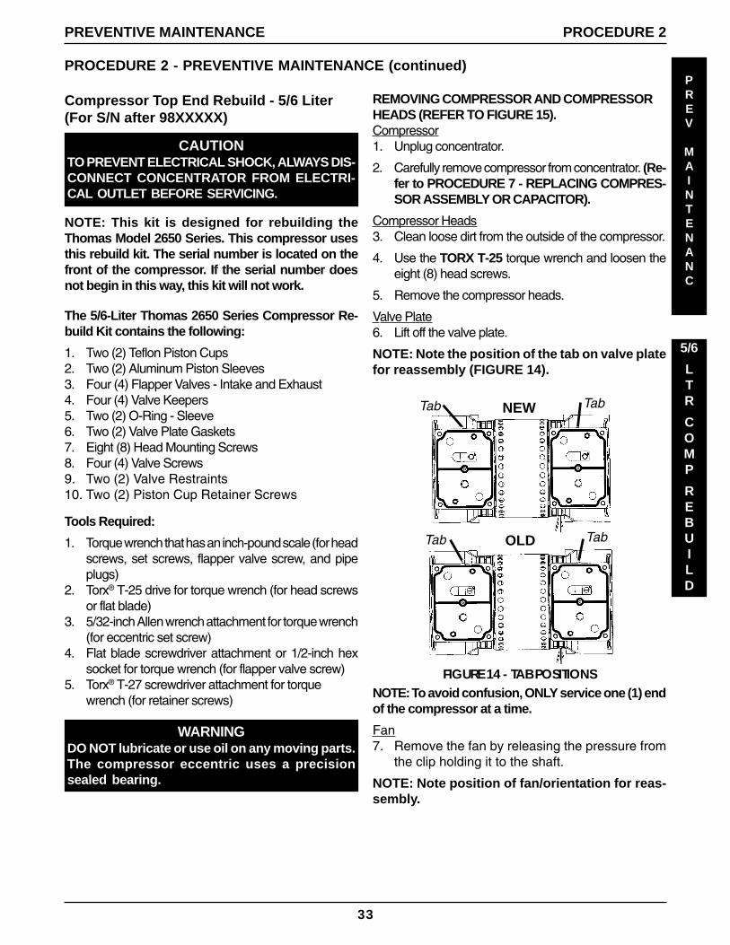
Compressor Top End Rebuild - 5/6 Liter(For S/N after 98XXXXX)
PROCEDURE 2 - PREVENTIVE MAINTENANCE (continued)
5/6
LTR
COMP
REBUILD
PROCEDURE 2PREVENTIVE MAINTENANCE
PREV
MAINTENANC
Tools Required:
1. Torque wrench that has an inch-pound scale (for headscrews, set screws, flapper valve screw, and pipeplugs)
2. Torx® T-25 drive for torque wrench (for head screwsor flat blade)
3. 5/32-inch Allen wrench attachment for torque wrench(for eccentric set screw)
4. Flat blade screwdriver attachment or 1/2-inch hexsocket for torque wrench (for flapper valve screw)
5. Torx® T-27 screwdriver attachment for torquewrench (for retainer screws)
REMOVING COMPRESSOR AND COMPRESSORHEADS (REFER TO FIGURE 15).Compressor1. Unplug concentrator.
2. Carefully remove compressor from concentrator. (Re-fer to PROCEDURE 7 - REPLACING COMPRES-SOR ASSEMBLY OR CAPACITOR).
Compressor Heads3. Clean loose dirt from the outside of the compressor.
4. Use the TORX T-25 torque wrench and loosen theeight (8) head screws.
5. Remove the compressor heads.
Valve Plate6. Lift off the valve plate.
NOTE: Note the position of the tab on valve platefor reassembly (FIGURE 14).
NOTE: To avoid confusion, ONLY service one (1) endof the compressor at a time.
Fan7. Remove the fan by releasing the pressure from
the clip holding it to the shaft.
NOTE: Note position of fan/orientation for reas-sembly.
Tab Tab
Tab TabOLD
NEW
FIGURE 14 - TAB POSITIONS
34
PREV
MAINTENANCE
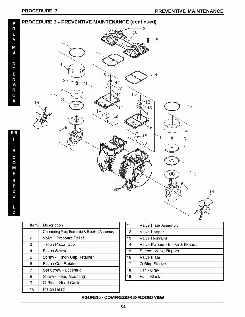
FIGURE 15 - COMPRESSOR EXPLODED VIEW
PROCEDURE 2 - PREVENTIVE MAINTENANCE (continued)
PREVENTIVE MAINTENANCEPROCEDURE 2
5/6
LTR
COMP
REBUILD
Item Description
1 Connecting Rod, Eccentric & Bearing Assembly
2 Valve - Pressure Relief
3 Teflon Piston Cup
4 Piston Sleeve
5 Screw - Piston Cup Retainer
6 Piston Cup Retainer
7 Set Screw - Eccentric
8 Screw - Head Mounting
9 O-Ring - Head Gasket
10 Piston Head
11 Valve Plate Assembly
12 Valve Keeper
13 Valve Restraint
14 Valve Flapper - Intake & Exhaust
15 Screw - Valve Flapper
16 Valve Plate
17 O-Ring Sleeve
18 Fan - Gray
19 Fan - Black
2
35
PROCEDURE 2 - PREVENTIVE MAINTENANCE (continued)
PROCEDURE 2PREVENTIVE MAINTENANCE
PREV
MAINTENANCE
Connecting Rod/Eccentric Assembly8. Rotate shaft to align the eccentric's set screw
with the access hole in the bottom of the com-pressor housing.
9. Insert the 5/32-inch allen wrench into the accesshole in the bottom of the compressor housing.
10. Loosen the setscrew 1/4 turn.
11. Rotate connecting rod to top dead center (1800)and slide the connecting rod/eccentric assem-bly off the shaft.
12. Secure the rod assembly in a fixture.
13. Remove the sleeve from the connecting rod anddiscard.
Piston Cup14. Remove the screw (discard) from the cup re-
tainer (retain for reassembly).
15. Remove the piston cup (discard) and wipe de-bris from the top of the connecting rod with aclean damp cloth.
O-ring, Intake Valve and Valve Keeper16. Remove the O-ring, intake valve and valve
keeper from the bottom of the valve plate. Dis-card all.
17. Clean the bottom of the valve plate with a clean,soft cloth.
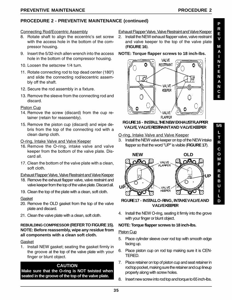
Exhaust Flapper Valve, Valve Restraint and Valve Keeper18. Remove the exhaust flapper valve, valve restraint and
valve keeper from the top of the valve plate. Discard all.
19. Clean the top of the plate with a clean, soft cloth.
Gasket20. Remove the OLD gasket from the top of the valve
plate and discard.
21. Clean the valve plate with a clean, soft cloth.
REBUILDING COMPRESSOR (REFER TO FIGURE 15).NOTE: Before reassembly, wipe any residue fromall components with a clean soft cloth.
Gasket1. Install NEW gasket; seating the gasket firmly in
the groove at the top of the valve plate with yourfinger or blunt object.
CAUTIONMake sure that the O-ring is NOT twisted whenseated in the groove of the top of the valve plate.
O-ring, Intake Valve and Valve Keeper3. Install the NEW valve keeper on top of the NEW intake
flapper so that the word "UP" is visible (FIGURE 17).
4. Install the NEW O-ring, seating it firmly into the grovewith your finger or blunt object.
NOTE: Torque flapper screws to 18 inch-lbs.
Piston Cup
5. Place cylinder sleeve over rod top with smooth edgefacing up.
6. Place piston cup on rod top making sure it is CEN-TERED.
7. Place retainer on top of piston cup and seat retainer inrod top pocket, making sure the retainer and cup lineupproperly along with screw holes.
8. Insert new screw into rod top and torque to 65 inch-lbs.
Exhaust Flapper Valve, Valve Restraint and Valve Keeper2. Install the NEW exhaust flapper valve, valve restraint
and valve keeper to the top of the valve plate(FIGURE 16).
NOTE: Torque flapper screws to 18 inch-lbs.
OLDNEW
FIGURE 16 - INSTALL THE NEW EXHAUST FLAPPERVALVE, VALVE RESTRAINT AND VALVE KEEPER
Fan14. Reinstall the fan onto the shaft in original orien-
tation.
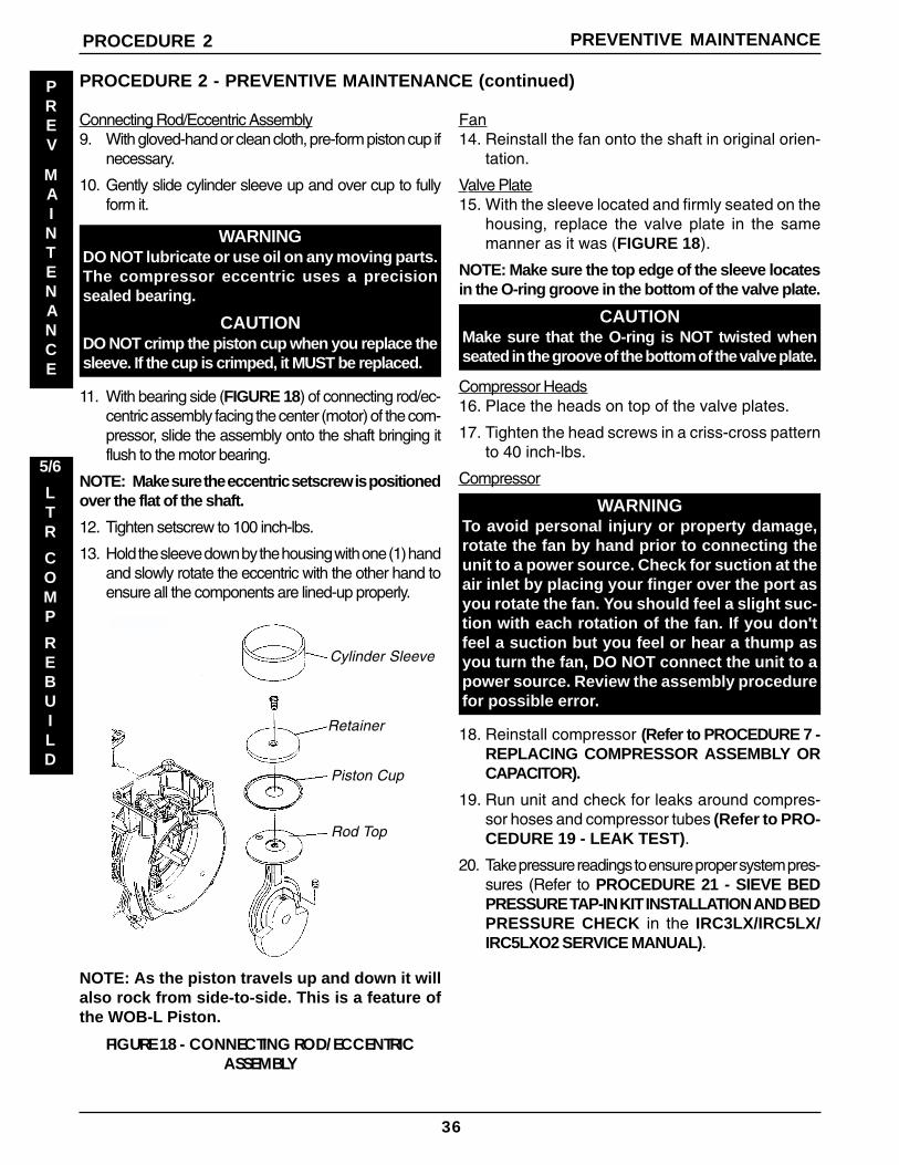
Valve Plate15. With the sleeve located and firmly seated on the
housing, replace the valve plate in the samemanner as it was (FIGURE 18).
NOTE: Make sure the top edge of the sleeve locatesin the O-ring groove in the bottom of the valve plate.
CAUTIONMake sure that the O-ring is NOT twisted whenseated in the groove of the bottom of the valve plate.
WARNINGDO NOT lubricate or use oil on any moving parts.The compressor eccentric uses a precisionsealed bearing.
CAUTIONDO NOT crimp the piston cup when you replace thesleeve. If the cup is crimped, it MUST be replaced.
11. With bearing side (FIGURE 18) of connecting rod/ec-centric assembly facing the center (motor) of the com-pressor, slide the assembly onto the shaft bringing itflush to the motor bearing.
NOTE: Make sure the eccentric setscrew is positionedover the flat of the shaft.
12. Tighten setscrew to 100 inch-lbs.
13. Hold the sleeve down by the housing with one (1) handand slowly rotate the eccentric with the other hand toensure all the components are lined-up properly.
Compressor Heads16. Place the heads on top of the valve plates.
17. Tighten the head screws in a criss-cross patternto 40 inch-lbs.
Compressor
WARNINGTo avoid personal injury or property damage,rotate the fan by hand prior to connecting theunit to a power source. Check for suction at theair inlet by placing your finger over the port asyou rotate the fan. You should feel a slight suc-tion with each rotation of the fan. If you don'tfeel a suction but you feel or hear a thump asyou turn the fan, DO NOT connect the unit to apower source. Review the assembly procedurefor possible error.
19. Run unit and check for leaks around compres-sor hoses and compressor tubes (Refer to PRO-CEDURE 19 - LEAK TEST).
20. Take pressure readings to ensure proper system pres-sures (Refer to PROCEDURE 21 - SIEVE BEDPRESSURE TAP-IN KIT INSTALLATION AND BEDPRESSURE CHECK in the IRC3LX/IRC5LX/IRC5LXO2 SERVICE MANUAL).
Connecting Rod/Eccentric Assembly9. With gloved-hand or clean cloth, pre-form piston cup if
necessary.
10. Gently slide cylinder sleeve up and over cup to fullyform it.
NOTE: As the piston travels up and down it willalso rock from side-to-side. This is a feature ofthe WOB-L Piston.
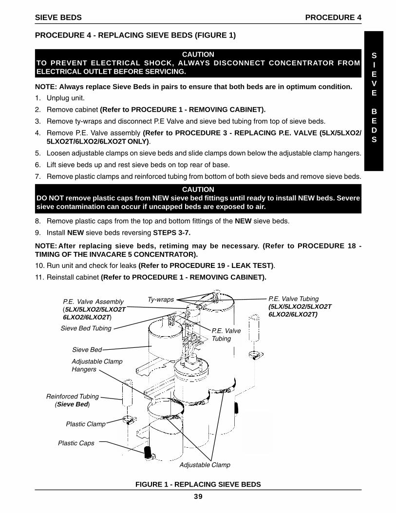
5. Loosen adjustable clamps on sieve beds and slide clamps down below the adjustable clamp hangers.
6. Lift sieve beds up and rest sieve beds on top rear of base.
7. Remove plastic clamps and reinforced tubing from bottom of both sieve beds and remove sieve beds.
PROCEDURE 4 - REPLACING SIEVE BEDS (FIGURE 1)
CAUTIONDO NOT remove plastic caps from NEW sieve bed fittings until ready to install NEW beds. Severesieve contamination can occur if uncapped beds are exposed to air.
8. Remove plastic caps from the top and bottom fittings of the NEW sieve beds.
9. Install NEW sieve beds reversing STEPS 3-7.
NOTE: After replacing sieve beds, retiming may be necessary. (Refer to PROCEDURE 18 -TIMING OF THE INVACARE 5 CONCENTRATOR).
SIEVE BEDS PROCEDURE 4
10. Run unit and check for leaks (Refer to PROCEDURE 19 - LEAK TEST).
11. Reinstall cabinet (Refer to PROCEDURE 1 - REMOVING CABINET).
2. Remove cabinet (Refer to PROCEDURE 1 - REMOVING CABINET)
NOTE: Replace one or both check valves when performing this procedure. The check valves areone-way directional and can be checked by passing air through them. Air should flow in onedirection ONLY.
3. Loosen adjustable clamp on product tank and slide clamp down below the adjustable clamp hanger toaccess check valve(s).
4. Remove ty-wraps from top and bottom of the check valve(s) and disconnect check valve(s) from tygontubing.
PROCEDURE 5 CHECK VALVES
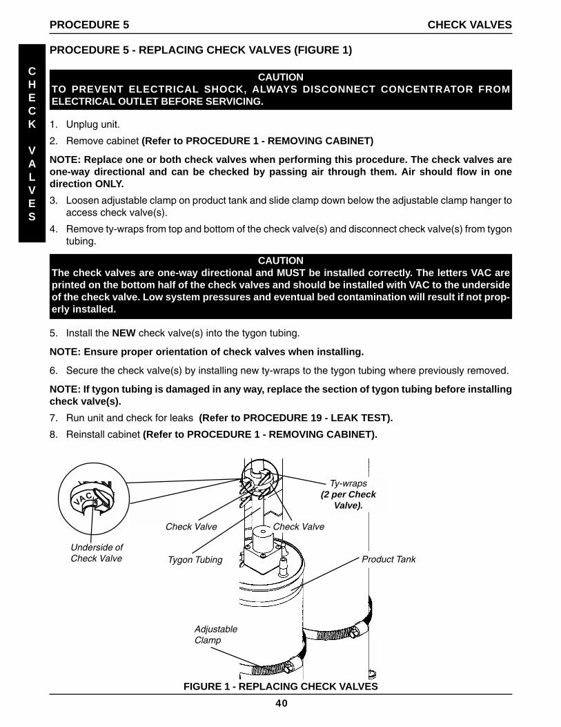
CAUTIONThe check valves are one-way directional and MUST be installed correctly. The letters VAC areprinted on the bottom half of the check valves and should be installed with VAC to the undersideof the check valve. Low system pressures and eventual bed contamination will result if not prop-erly installed.
Check Valve
Tygon Tubing Product Tank
Check Valve
AdjustableClamp
FIGURE 1 - REPLACING CHECK VALVES
VAC
Underside ofCheck Valve
Ty-wraps(2 per Check
Valve).
5. Install the NEW check valve(s) into the tygon tubing.
NOTE: Ensure proper orientation of check valves when installing.
6. Secure the check valve(s) by installing new ty-wraps to the tygon tubing where previously removed.
NOTE: If tygon tubing is damaged in any way, replace the section of tygon tubing before installingcheck valve(s).
7. Run unit and check for leaks (Refer to PROCEDURE 19 - LEAK TEST).
8. Reinstall cabinet (Refer to PROCEDURE 1 - REMOVING CABINET).
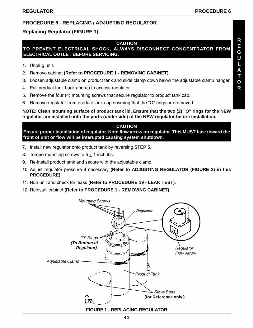
2. Remove cabinet (Refer to PROCEDURE 1 - REMOVING CABINET).
3. Loosen adjustable clamp on product tank and slide clamp down below the adjustable clamp hanger.
4. Pull product tank back and up to access regulator.
5. Remove the four (4) mounting screws that secure regulator to product tank cap.
6. Remove regulator from product tank cap ensuring that the "O" rings are removed.
NOTE: Clean mounting surface of product tank lid. Ensure that the two (2) "O" rings for the NEWregulator are installed onto the ports (underside) of the NEW regulator before installation.
REGULATOR PROCEDURE 6
FIGURE 1 - REPLACING REGULATOR
Regulator
"O" Rings(To Bottom of
Regulator).
Adjustable Clamp
Sieve Beds(for Reference only.)
CAUTIONEnsure proper installation of regulator. Note flow arrow on regulator. This MUST face toward thefront of unit or flow will be interupted causing system shutdown.
7. Install new regulator onto product tank by reversing STEP 5.
8. Torque mounting screws to 5 + 1 inch lbs.
9. Re-install product tank and secure with the adjustable clamp.
10. Adjust regulator pressure if necessary (Refer to ADJUSTING REGULATOR (FIGURE 2) in thisPROCEDURE).
11. Run unit and check for leaks (Refer to PROCEDURE 19 - LEAK TEST).
12. Reinstall cabinet (Refer to PROCEDURE 1 - REMOVING CABINET).
RegulatorFlow Arrow
Product Tank
Mounting Screws
42
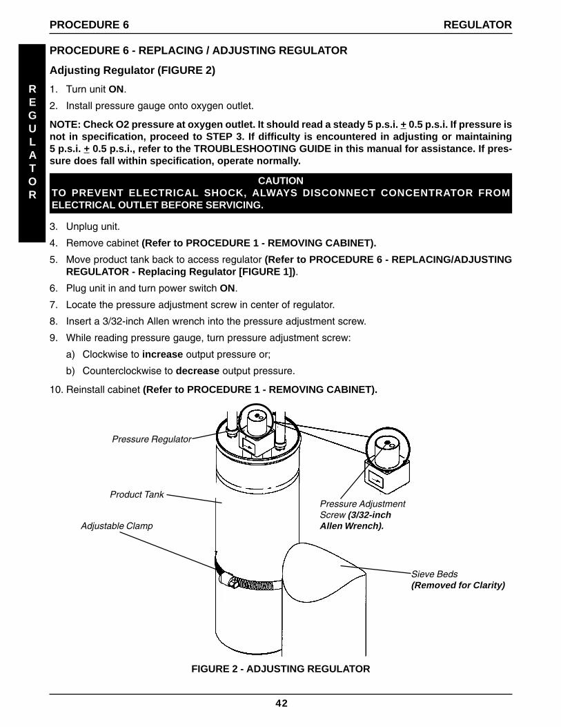
PROCEDURE 6 - REPLACING / ADJUSTING REGULATOR
Adjusting Regulator (FIGURE 2)
REGULATOR
PROCEDURE 6 REGULATOR
1. Turn unit ON.
2. Install pressure gauge onto oxygen outlet.
NOTE: Check O2 pressure at oxygen outlet. It should read a steady 5 p.s.i. + 0.5 p.s.i. If pressure isnot in specification, proceed to STEP 3. If difficulty is encountered in adjusting or maintaining5 p.s.i. + 0.5 p.s.i., refer to the TROUBLESHOOTING GUIDE in this manual for assistance. If pres-sure does fall within specification, operate normally.
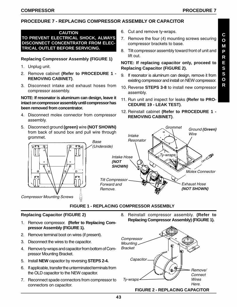
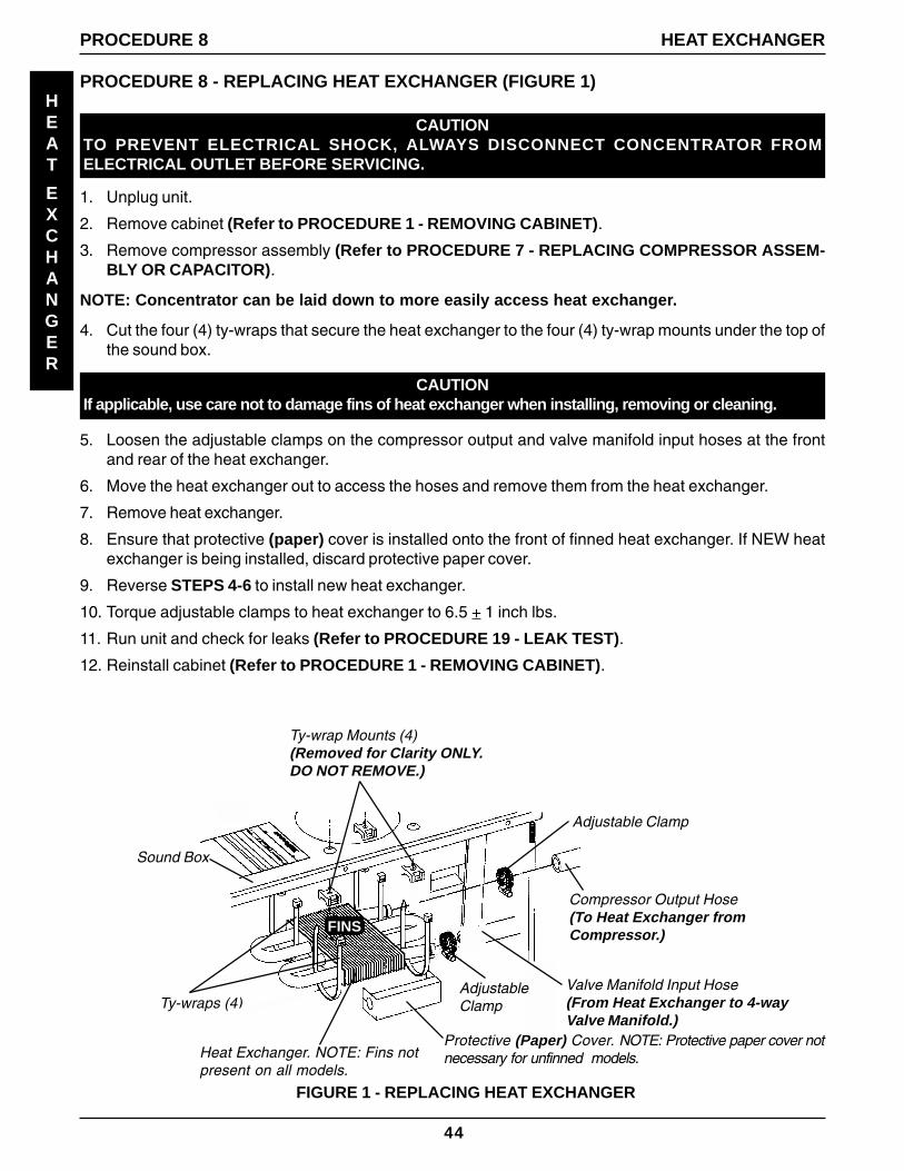
2. Remove cabinet (Refer to PROCEDURE 1 - REMOVING CABINET).
3. Remove compressor assembly (Refer to PROCEDURE 7 - REPLACING COMPRESSOR ASSEM-BLY OR CAPACITOR).
NOTE: Concentrator can be laid down to more easily access heat exchanger.
4. Cut the four (4) ty-wraps that secure the heat exchanger to the four (4) ty-wrap mounts under the top ofthe sound box.
HEAT
EXCHANGER
CAUTIONIf applicable, use care not to damage fins of heat exchanger when installing, removing or cleaning.
PROCEDURE 8 HEAT EXCHANGER
5. Loosen the adjustable clamps on the compressor output and valve manifold input hoses at the frontand rear of the heat exchanger.
6. Move the heat exchanger out to access the hoses and remove them from the heat exchanger.
7. Remove heat exchanger.
8. Ensure that protective (paper) cover is installed onto the front of finned heat exchanger. If NEW heatexchanger is being installed, discard protective paper cover.
9. Reverse STEPS 4-6 to install new heat exchanger.
10. Torque adjustable clamps to heat exchanger to 6.5 + 1 inch lbs.
11. Run unit and check for leaks (Refer to PROCEDURE 19 - LEAK TEST).
12. Reinstall cabinet (Refer to PROCEDURE 1 - REMOVING CABINET).
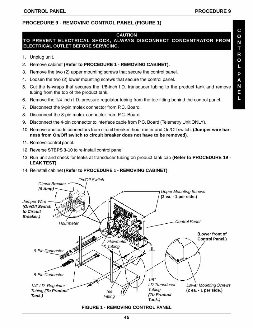
2. Remove cabinet (Refer to PROCEDURE 1 - REMOVING CABINET).
3. Remove the two (2) upper mounting screws that secure the control panel.
4. Loosen the two (2) lower mounting screws that secure the control panel.
5. Cut the ty-wraps that secures the 1/8-inch I.D. transducer tubing to the product tank and removetubing from the top of the product tank.
6. Remove the 1/4-inch I.D. pressure regulator tubing from the tee fitting behind the control panel.
7. Disconnect the 9-pin molex connector from P.C. Board.
8. Disconnect the 8-pin molex connector from P.C. Board.
9. Disconnect the 4-pin connector to interface cable from P.C. Board (Telemetry Unit ONLY).
10. Remove and code connectors from circuit breaker, hour meter and On/Off switch. (Jumper wire har-ness from On/Off switch to circuit breaker does not have to be removed).
11. Remove control panel.
12. Reverse STEPS 3-10 to re-install control panel.
13. Run unit and check for leaks at transducer tubing on product tank cap (Refer to PROCEDURE 19 -LEAK TEST).
14. Reinstall cabinet (Refer to PROCEDURE 1 - REMOVING CABINET).
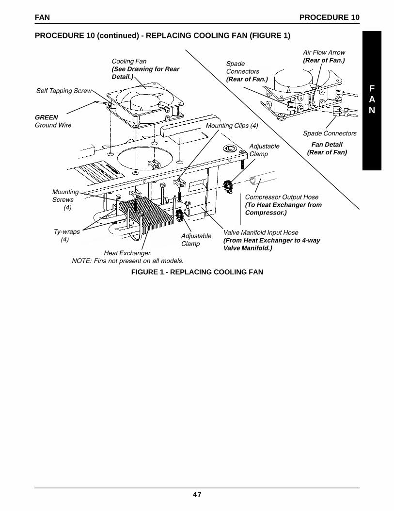
NOTE: Before removing the four (4) mounting clips, note their position. These clips must be prop-erly reinstalled to secure heat exchanger.
6. Remove the four (4) mounting screws located under sound box and remove mounting clips.
7. Move fan to access the wires connected to fan.
8. Disconnect wires from spade connectors on back side of fan.
9. Remove GREEN ground wire from rear of fan by removing self-tapping screw on fan assembly.
10. Remove existing fan.
FAN
PROCEDURE 10 FAN
WARNINGFan must be positioned properly so air from the fan blows DOWN onto the compressor (see airflow arrow on back of fan) or damage to the unit will occur.
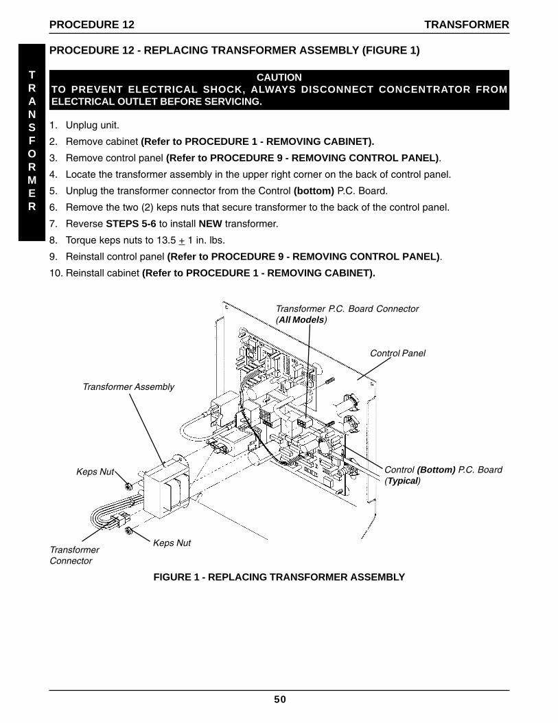
2. Remove cabinet (Refer to PROCEDURE 1 - REMOVING CABINET).
3. Remove control panel (Refer to PROCEDURE 9 - REMOVING CONTROL PANEL).
WARNINGONLY QUALIFIED SERVICE TECHNICIANS SHOULD MAKE ANY CHANGES TO THIS EQUIPMENT.
These are precautions that should be followed to prevent damage to the P. C. boards:Before handling any P. C. boards, you need to be properly grounded to prevent static damage tothe components of the board. A Static Cuff must be worn and properly grounded using an alliga-tor clip. Electrical conduit or a water pipe is normally sufficient when a known good ground is notavailable. Care should be taken to ensure that alligator clip contact with bare metal surface.
When removing quick disconnects, DO NOT pull on wire itself as damage to the connector orsolder joint may occur. Hold down the P. C. board with one hand and use an upward force with aslight rocking motion to remove the terminals.
Before installing any P. C. boards, ensure that all insulators are in place.
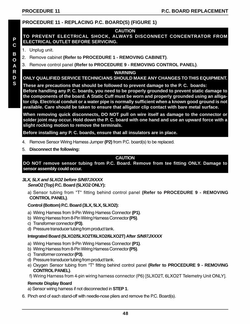
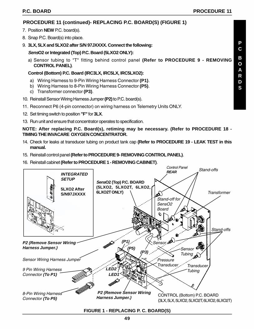
4. Remove Sensor Wiring Harness Jumper (P2) from P.C. board(s) to be replaced.
5. Disconnect the following:
CAUTIONDO NOT remove sensor tubing from P.C. Board. Remove from tee fitting ONLY. Damage tosensor assembly could occur.
3LX, 5LX and 5LXO2 before S/N97JXXXXSensO2 (Top) P.C. Board (5LXO2 ONLY):
a) Sensor tubing from "T" fitting behind control panel (Refer to PROCEDURE 9 - REMOVINGCONTROL PANEL).
Control (Bottom) P.C. Board (3LX, 5LX, 5LXO2):
a) Wiring Harness from 9-Pin Wiring Harness Connector (P1).b) Wiring Harness from 8-Pin Wiring Harness Connector (P5).c) Transformer connector (P3).d) Pressure transducer tubing from product tank.
Integrated Board (5LXO2/5LXO2T/6LXO2/6LXO2T) After S/N97JXXXX
a) Wiring Harness from 9-Pin Wiring Harness Connector (P1).b) Wiring Harness from 8-Pin Wiring Harness Connector (P5).c) Transformer connector (P3).d) Pressure transducer tubing from product tank.e) Oxygen Sensor tubing from "T" fitting behind control panel (Refer to PROCEDURE 9 - REMOVING
CONTROL PANEL).f) Wiring Harness from 4-pin wiring harness connector (P6) [5LXO2T, 6LXO2T Telemetry Unit ONLY].
Remote Display Boarda) Sensor wiring harness if not disconnected in STEP 1.
6. Pinch end of each stand-off with needle-nose pliers and remove the P.C. Board(s).
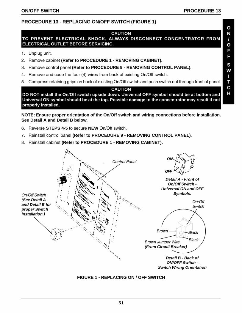
2. Remove cabinet (Refer to PROCEDURE 1 - REMOVING CABINET).
3. Remove control panel (Refer to PROCEDURE 9 - REMOVING CONTROL PANEL).
4. Remove and code the four (4) wires from back of existing On/Off switch.
5. Compress retaining grips on back of existing On/Off switch and push switch out through front of panel.
CAUTIONDO NOT install the On/Off switch upside down. Universal OFF symbol should be at bottom andUniversal ON symbol should be at the top. Possible damage to the concentrator may result if notproperly installed.
NOTE: Ensure proper orientation of the On/Off switch and wiring connections before installation.See Detail A and Detail B below.
6. Reverse STEPS 4-5 to secure NEW On/Off switch.
7. Reinstall control panel (Refer to PROCEDURE 9 - REMOVING CONTROL PANEL).
8. Reinstall cabinet (Refer to PROCEDURE 1 - REMOVING CABINET).
ON/OFF
SWITCH
ON
OFF
On/Off Switch(See Detail Aand Detail B forproper Switchinstallation.)
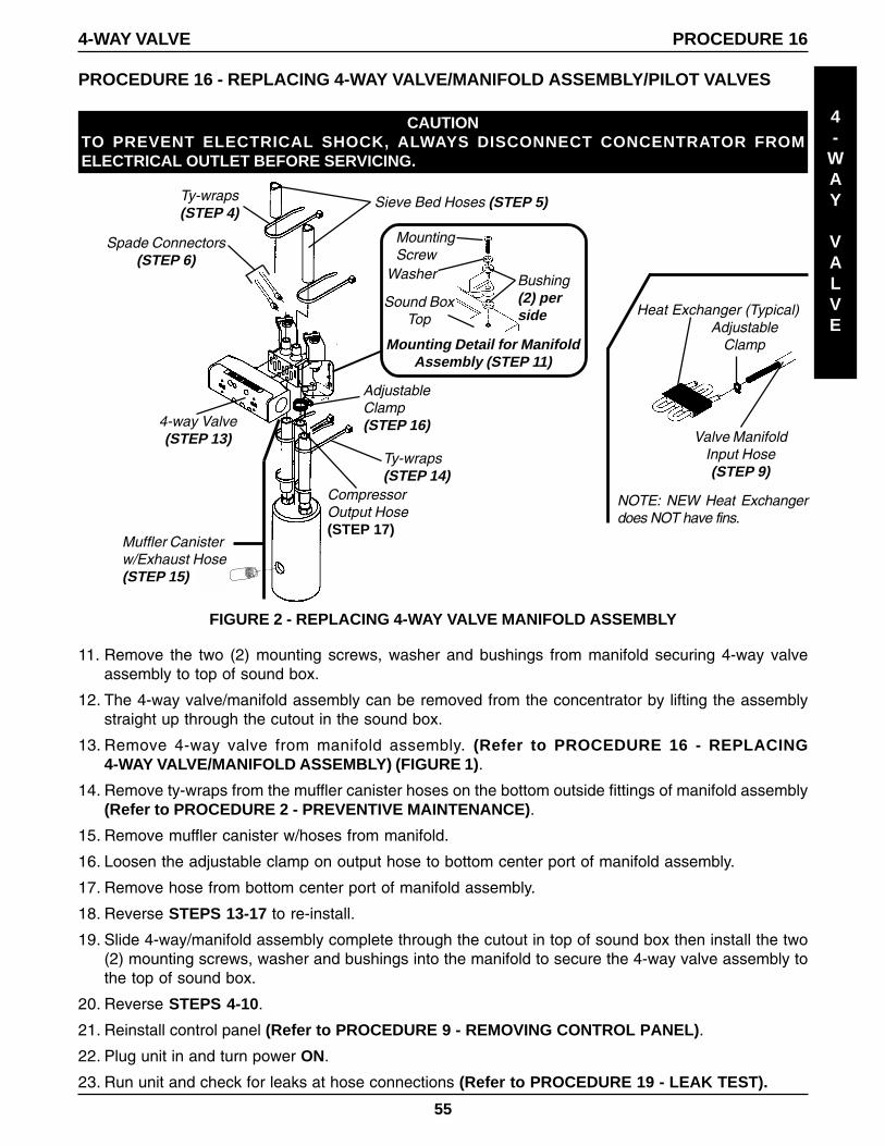
11. Remove the two (2) mounting screws, washer and bushings from manifold securing 4-way valveassembly to top of sound box.
12. The 4-way valve/manifold assembly can be removed from the concentrator by lifting the assemblystraight up through the cutout in the sound box.
13. Remove 4-way valve from manifold assembly. (Refer to PROCEDURE 16 - REPLACING4-WAY VALVE/MANIFOLD ASSEMBLY) (FIGURE 1).
14. Remove ty-wraps from the muffler canister hoses on the bottom outside fittings of manifold assembly(Refer to PROCEDURE 2 - PREVENTIVE MAINTENANCE).
15. Remove muffler canister w/hoses from manifold.
16. Loosen the adjustable clamp on output hose to bottom center port of manifold assembly.
17. Remove hose from bottom center port of manifold assembly.
18. Reverse STEPS 13-17 to re-install.
19. Slide 4-way/manifold assembly complete through the cutout in top of sound box then install the two(2) mounting screws, washer and bushings into the manifold to secure the 4-way valve assembly tothe top of sound box.
20. Reverse STEPS 4-10.
21. Reinstall control panel (Refer to PROCEDURE 9 - REMOVING CONTROL PANEL).
22. Plug unit in and turn power ON.
23. Run unit and check for leaks at hose connections (Refer to PROCEDURE 19 - LEAK TEST).
24. Check for proper system operation. (Refer to the SPECIFICATION section of this manual).
25. Re-install cabinet (Refer to PROCEDURE 1 - REMOVING CABINET).
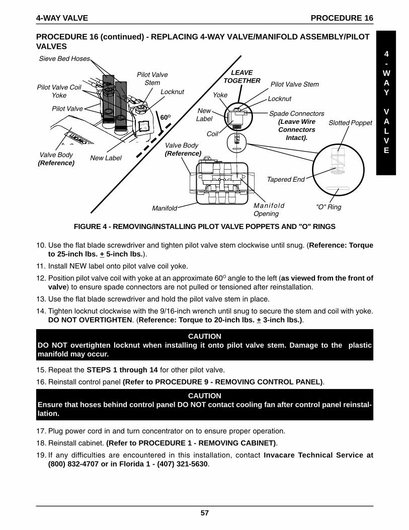
Replacing Pilot Valve Poppets and "O" Rings (FIGURES 3 & 4).
NOTE: Both pilot valves can be accessed while the 4-way valve and sieve bed hoses are intact onthe concentrator.NOTE: DO NOT remove spade connectors from pilot valve coils. Simply lay coils with spade con-nectors aside while performing this installation.
1. Hold pilot valve stem with the flat blade screwdriver and turn the 9/16-inch locknut counterclockwiseone (1) complete turn.
2. Unscrew the pilot valve stem assembly from the manifold while leaving the coil with yoke and locknutintact on stem.
3. Remove pilot valve poppet from inside the pilot valve stem.
STOP! DO NOT REMOVE THE COIL YOKE FROM THE COIL.The Washer between the Bottom of the Yoke and the Bottom of CoilIS NOT DESIGNED TO BE REMOVED and difficulty in reassemblywill be encountered that could cause damage to components.
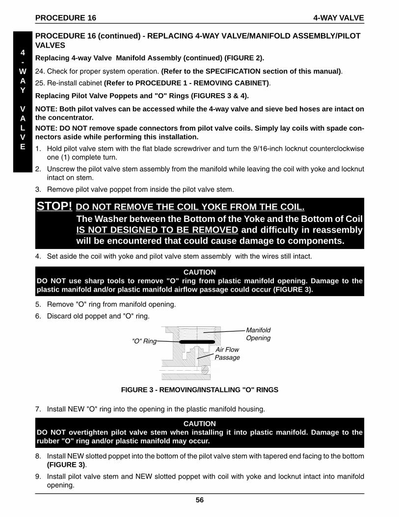
CAUTIONDO NOT use sharp tools to remove "O" ring from plastic manifold opening. Damage to theplastic manifold and/or plastic manifold airflow passage could occur (FIGURE 3).
5. Remove "O" ring from manifold opening.
6. Discard old poppet and "O" ring.
CAUTIONDO NOT overtighten pilot valve stem when installing it into plastic manifold. Damage to therubber "O" ring and/or plastic manifold may occur.
7. Install NEW "O" ring into the opening in the plastic manifold housing.
8. Install NEW slotted poppet into the bottom of the pilot valve stem with tapered end facing to the bottom(FIGURE 3).
9. Install pilot valve stem and NEW slotted poppet with coil with yoke and locknut intact into manifoldopening.
ManifoldOpening
Air FlowPassage
"O" Ring
FIGURE 3 - REMOVING/INSTALLING "O" RINGS
4. Set aside the coil with yoke and pilot valve stem assembly with the wires still intact.
15. Repeat the STEPS 1 through 14 for other pilot valve.
16. Reinstall control panel (Refer to PROCEDURE 9 - REMOVING CONTROL PANEL).
CAUTIONEnsure that hoses behind control panel DO NOT contact cooling fan after control panel reinstal-lation.
17. Plug power cord in and turn concentrator on to ensure proper operation.
18. Reinstall cabinet. (Refer to PROCEDURE 1 - REMOVING CABINET).
19. If any difficulties are encountered in this installation, contact Invacare Technical Service at(800) 832-4707 or in Florida 1 - (407) 321-5630.
CAUTIONDO NOT overtighten locknut when installing it onto pilot valve stem. Damage to the plasticmanifold may occur.
Slotted Poppet
10. Use the flat blade screwdriver and tighten pilot valve stem clockwise until snug. (Reference: Torqueto 25-inch lbs. + 5-inch lbs.).
11. Install NEW label onto pilot valve coil yoke.
12. Position pilot valve coil with yoke at an approximate 60O angle to the left (as viewed from the front ofvalve) to ensure spade connectors are not pulled or tensioned after reinstallation.
13. Use the flat blade screwdriver and hold the pilot valve stem in place.
14. Tighten locknut clockwise with the 9/16-inch wrench until snug to secure the stem and coil with yoke.DO NOT OVERTIGHTEN. (Reference: Torque to 20-inch lbs. + 3-inch lbs.).
Manifold
Locknut
Spade Connectors(Leave WireConnectors
Intact).
LEAVETOGETHER Pilot Valve Stem
"O" Ring
Tapered End
Locknut
Pilot ValveStem
60O
Pilot Valve
FIGURE 4 - REMOVING/INSTALLING PILOT VALVE POPPETS AND "O" RINGS
Yoke
NewLabel
Coil
Mani fo ldOpening
Pilot Valve CoilYoke
Sieve Bed Hoses
Valve Body(Reference)
New Label
Valve Body(Reference)
58
PROCEDURE 17 - SENSO2 ALARM INDICATORS AND SWITCH
PURITY
SWITCH
CAUTIONTO PREVENT ELECTRICAL SHOCK, ALWAYSDISCONNECT CONCENTRATOR FROM ELEC-TRICAL OUTLET BEFORE SERVICING.
Operation
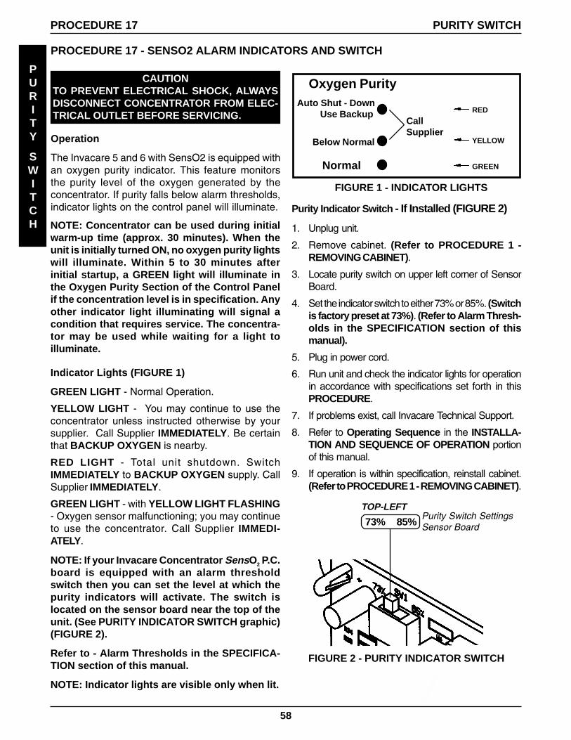
The Invacare 5 and 6 with SensO2 is equipped withan oxygen purity indicator. This feature monitorsthe purity level of the oxygen generated by theconcentrator. If purity falls below alarm thresholds,indicator lights on the control panel will illuminate. Purity Indicator Switch - If Installed (FIGURE 2)
1. Unplug unit.
2. Remove cabinet. (Refer to PROCEDURE 1 -REMOVING CABINET).
3. Locate purity switch on upper left corner of SensorBoard.
4. Set the indicator switch to either 73% or 85%. (Switchis factory preset at 73%). (Refer to Alarm Thresh-olds in the SPECIFICATION section of thismanual).
5. Plug in power cord.
6. Run unit and check the indicator lights for operationin accordance with specifications set forth in thisPROCEDURE.
7. If problems exist, call Invacare Technical Support.
8. Refer to Operating Sequence in the INSTALLA-TION AND SEQUENCE OF OPERATION portionof this manual.
9. If operation is within specification, reinstall cabinet.(Refer to PROCEDURE 1 - REMOVING CABINET).
NOTE: Concentrator can be used during initialwarm-up time (approx. 30 minutes). When theunit is initially turned ON, no oxygen purity lightswill illuminate. Within 5 to 30 minutes afterinitial startup, a GREEN light will illuminate inthe Oxygen Purity Section of the Control Panelif the concentration level is in specification. Anyother indicator light illuminating will signal acondition that requires service. The concentra-tor may be used while waiting for a light toilluminate.
Indicator Lights (FIGURE 1)
GREEN LIGHT - Normal Operation.
YELLOW LIGHT - You may continue to use theconcentrator unless instructed otherwise by yoursupplier. Call Supplier IMMEDIATELY. Be certainthat BACKUP OXYGEN is nearby.
RED LIGHT - Total unit shutdown. SwitchIMMEDIATELY to BACKUP OXYGEN supply. CallSupplier IMMEDIATELY.
GREEN LIGHT - with YELLOW LIGHT FLASHING- Oxygen sensor malfunctioning; you may continueto use the concentrator. Call Supplier IMMEDI-ATELY.
NOTE: If your Invacare Concentrator SensO2 P.C.board is equipped with an alarm thresholdswitch then you can set the level at which thepurity indicators will activate. The switch islocated on the sensor board near the top of theunit. (See PURITY INDICATOR SWITCH graphic)(FIGURE 2).
Refer to - Alarm Thresholds in the SPECIFICA-TION section of this manual.
NOTE: Indicator lights are visible only when lit.
PROCEDURE 17 PURITY SWITCH
TOP-LEFTPurity Switch SettingsSensor Board
FIGURE 2 - PURITY INDICATOR SWITCH
Auto Shut - DownUse Backup
CallSupplier
Normal
Below Normal
Oxygen Purity
RED
YELLOW
GREEN
FIGURE 1 - INDICATOR LIGHTS
73% 85%
59
PROCEDURE 18 - TIMING THE INVACARE 5 AND 6 CONCENTRATORS (FIGURE 1)
To accommodate for varying tolerances when replacing components, an adjustable timer is used tocontrol the shifting of the INVACARE 5 and 6 Pressure Equalization (P.E.) Valve. Retiming of a unitinvolves increasing or decreasing the switch located on the lower right side of the bottom P.C. Board.
1. Unplug unit.
2. Remove cabinet. (Refer to PROCEDURE 1 - REMOVING CABINET).
3. Plug concentrator in, and turn power on, set flow at 5 L/min. for the IRC5LX/IRC5LXO2.
4. Run unit for 20 minutes.
5. Take O2 reading.
6. If oxygen concentration is within specification, retiming is not necessary.
7. Unplug unit and reinstall cabinet.
UNITS WITH CONTROL BOARD OR LX SMT BOARD IRC5LX/5LXO2
1. If retiming is needed, perform the following:
a) Unplug unit.
b) Remove or loosen control Panel. (Refer to PROCEDURE 9 - REMOVING CONTROL PANEL).
c) Locate the timing switch on the lower right side of the bottom P.C. Board.
Control Panel
WARNINGUse extreme care when making adjustments to the timing switch. DO NOT allow screwdriver oryour hands to contact the P.C. Board when unit is plugged in and ON. Turn unit OFF and unplugbefore adjusting timing switch. Electrical shock is possible.
60
PROCEDURE 18 UNITS WITH CONTROL BOARD OR LX SMT BOARD IRC5LX/5LXO2 (FIGURE 1)(CONTINUED)
TI
MING
d) Insert a small common or flathead screwdriver into the adjustment screw of the timing switch.
e) Set the timing switch initially at the number 7 position.
2. Turn unit on.
3. If after 10 minutes of run time the concentration is below specification, change setting to a numberone (1) position lower than the previous setting.
4. Let unit run another 10 minutes. If concentration is lower still, change the switch to a number two (2)positions higher.
NOTE: You will find that the concentrator will perform better at either the higher or lower setting.The normal adjustment range is between 3 and A.
5. Continue to change setting one (1) step at a time (up or down) until the concentration is the highestvalue achievable. (Refer to CONCENTRATION LEVELS Chart in this PROCEDURE of the Manual.)
6. Once concentration has reached specification, retiming is complete.
7. Reinstall inlet filter.
8. Reinstall control panel. (Refer to PROCEDURE 9 - REMOVING CONTROL PANEL).
9. Reinstall cabinet. (Refer to PROCEDURE 1 - REMOVING CABINET).
TIMING IRC5LXO2/5LXO2T/6LXO2/6LXO2T - UNITS WITH INTEGRATED OR TELEMETRYBOARDS (FIGURE 1)
To accomodate the varying tolerances when replacing components, an adjustable timer is used to control the shifttime of the pressure equlization (P. E.) valve. The integrated and telemetry boards allow for either manual orautomatic (microprocessor controlled) adjustments of the P.E. shift times.
If manual adjustments is preferred, please refer to SECTION A of this procedure.
Automatic adjustment is performed by the onboard microprocessor to optimize the oxygen output concentration.Unattended operation is possible without the use of any additional manual adjustments.
1. Turn power OFF and unplug the unit.
2. Remove cabinet. (Refer to PROCEDURE 1 - REMOVING CABINET).
3. a. If the intergrated or telemetry board has beeen replaced, set the timing switch to position "0".b. If the intergrated or telemetry board has NOT beeen replaced, set the timing switch to position "F".
4. Replace the cabinet. Plug concentrator in, and turn power on, set flow at 5 L/min. for the IRC5LXO2/IRC5LXO2Tand 6 L/min. for the IRC6LXO2/IRC6LXO2T.
NOTE: The flow MUST be at rated output for optimum adjustment of oxygen output for all flow ranges.
5. After the FIRST valve shift, the front panel Red LED will slowly blink. This indicates that the unit is in the auto-tune mode. The microprocessor automatically adjusts the length of the P.E. valve timing up or down to providemaximum value of oxygen concentration for the unit at rated flow.
6. a. If the switch is set to position "0", the auto-tune will take a minimum of three (3) hours to complete.b. If the switch is set to position "F", the auto-tune will take a minimum of 45 minutes to complete.
7. If the front panel Red LED does NOT blink or the unit alarms immediately, check the timimg switch position.
8. When the auto-tune procedure is completed, the alarm will sound every 3-4 seconds and the front panel RedLED will change from slowly blinking to rapid flashing. Count the number of Red LED flashes between thepauses. This indicates the P.E. timing value the microprocessor has determined as optimum for maximum
PROCEDURE 18 TIMING
61
PROCEDURE 18TIMING
TI
MING
oxygen production. This Red LED count corresponds to the same numbers on the timing switch inthe manual mode. Record this number.
9. If the timing switch was in position "0" at the start, turn the unit OFF and then BACK on. The unit willnow function normally. The timimg value is stored in the microprocessor's memory and is recalledeverytime the unit is turned back ON.
10. If the timing switch was in position "F" at the start, remove the cabinet and change the position to "0".The alarm should stop sounding and the Red LED will stop flashing. The unit will now functionnormally. The timimg value is stored in the microprocessor's memory and is recalled everytime theunit is turned back ON.
11. The timing switch MUST be in position "0" for the automatic control of the P.E. valve time by the unit'smicroprocessor for maximum oxygen concentration. The timing switch can be changed to manualcontrol by selecting position "1" to "E". Verification of oxygen production MUST be performed accord-ing to SECTION A of this procedure.
L/Min. O2 Level
1 L/min. 95.6% to 93%
2 L/min. 95.6% to 93%
3 L/min. 95.6% to 93%
4 L/min. 95.6% to 91%
5 L/min. 95.6% to 87%
6 L/min. 95.6% to 87%
CONCENTRATION LEVELS CHART - (IRC5LX/5LXO2/6LXO2)
62
PROCEDURE 19 - LEAK TEST(FIGURES 1-3)
CAUTIONTO PREVENT ELECTRICAL SHOCK, ALWAYSDISCONNECT CONCENTRATOR FROMELECTRICAL OUTLET BEFORE SERVICING.
Leak Test
1. Unplug unit.
2. Remove cabinet. (Refer to PROCEDURE 1 -REMOVING CABINET).
3. Turn the concentrator on.
4. Let concentrator run for 20 minutes.
CAUTIONApply small amount of leak test solution to fit-tings only. Avoid all other components. DO NOTleak test 4-way Valve body. Carefully leak testfor pressure leaks around Sieve Bed Hoses at4-way Valve. DO NOT allow leak test solutionto enter into 4-way Valve and system.
5. With "leak-test" or equivalent soapy water, leaktest the following:
a) The two (2) sieve bed hoses at the top of4-way Valve and hose to bottom center porton 4-way Valve (FIGURE 1).
NOTE: Refer to PROCEDURE 2 - PREVENTIVEMAINTENANCE for maintenance of heatexchanger and filters.
b) Hose connections to top and bottom fittings ofsieve beds.
c) P.E. Valve hose connections on top of sievebeds - IRC 5LX/IRC5LXO2 (FIGURE 2).
d) Hose fittings at product tank cap and checkvalves (FIGURE 2).
e) The front and rear fittings on heat exchanger(FIGURE 3).
6. Replace any tubing that appears cracked, worn,etc.
7. Re-install cabinet. (Refer to PROCEDURE 1 -REMOVING CABINET).
8. See SPECIFICATION section of this manualfor Concentration Levels. If low concentrationsare observed, refer to the TROUBLESHOOT-ING GUIDE in this manual.
LEAK
TEST
PROCEDURE 19 LEAK TEST
Sieve Bed Hosesto 4-way Valve(STEP 5-a).
Hose Fitting onBottom Center Portof 4-way Valve(STEP5-a).
CAUTIONCHECK ALARMS PERIODICALLY FOR PROPER FUNCTION.
To check each alarm, perform the following:
1. POWER LOSS - With the unit running, remove the line cord from power source. The power loss alarmmode should sound the audible alarm immediately or within 30 seconds.
NOTE: With the unit unplugged and inoperable for a short period of time, the Battery FreeTM circuitwill be drained. If power failure alarm does not sound with unit unplugged and power switch on,the Battery FreeTM circuit is drained. It will recharge when unit is plugged in and switched on.
2. LOW PRESSURE TEST- There are two (2) seperate failure modes for Low Pressure.
a. Low product tank pressure (pressure in tank drops below a preset value, typically 7 p.s.i).
b. Failure to reach the set point pressure within a prescribed time limit, or Timeout Failure.
Test each in the following manner:
Low Pressure Test (FIGURE 1).
c1. With unit running, set flow at maximum rating. When the main valve switches, pull the stem on thecompressor relief valve out as far as it will go and hold it. The low pressure alarm should activate within 30seconds. (Refer to FIGURE 5 for Shutdown Mode.)
c2. With unit running, set flow at maximum rating. Remove the P.C. board tubing (tywrap) from the topof the product tank The low pressure alarm should activate within 30 seconds. (Refer to FIGURE 5 forShutdown Mode.) Replace tubing and tywrap.
Time-Out Test (FIGURE 1)
d. With unit OFF, disconnect the compressor connector from the main wiring harness. Plugunit in and turn power ON. The Time-Out Failure alarm should activate within 40 seconds. (Referto FIGURE 5 for Shutdown Mode.)
NOTE: If any alarm fails to perform to specification, contact Invacare Technical Service.
Relief Valve Stem[Pull Out to SimulateLeak (STEP 2-a)].
64
3. HIGH PRESSURE - Occurs when pressure in product tank rises beyond a preset value, typically23 p.s.i. + 1 p.s.i.
Test in the following manner:
High Pressure Test (FIGURE 2).
3-a. With unit running and flow set at 3 L/min. for 3LX, 5 L/min. for 5LX/5LXO2 or 6 L/min. for 6LXO2,remove one (1) RED wire from the top of Pilot Valve 1. The high pressure alarm should activatewithin 40 seconds. (Refer to FIGURE 5 for Shutdown Mode.)
3-b. Set flow at 3 l/min. for 3LX, 5 L/min. for 5LX/5LXO2 or 6 L/min. for 6LXO2. Turn unit OFF andremove one (1) RED wire from the top of Pilot Valve 1. Turn unit ON. The high pressure alarmshould activate within 30 seconds. (Refer to FIGURE 5 for Shutdown Mode.)
NOTE: If any alarm fails to perform to specification, contact Invacare Technical Service.
4. OXYGEN SENSOR (5LXO2/6LXO2) - Alarm sequence occurs when concentration levels fall belowa preset value, typically 73% + 3% or 85% + 2%. This failure indicates a catastrophic failure of anycomponent mechanical or electrical. This test is performed in a series of STEPS.
Test in the following manner:
Oxygen Sensor Test (FIGURE 3)
Ensure that Purity Switch (SW1) is set at 73%. (Refer to PROCEDURE 17 - SENSO2 ALARMINDICATOR AND SWITCH in this manual).
4-a. Turn unit ON. Set output flow at 5 L/min. (5LXO2) or 6 L/min. (6LXO2).
4-b. Monitor the O2 level.
4-c. With the O2 level greater than 85% after 5 minutes, the GREEN panel LED will illuminate.
4-d. Slowly adjust flow beyond maximum rated flow until you can achieve a concentration level greaterthan 75% but less than 84%. Within 30 min. the YELLOW panel LED indicator will illuminate andthe unit will continue to run.
RED Wires[Remove Either Wire -STEPS 3-a and 3-b)].
CAUTIONUse care not to cut oxygen sensor tubing when clamping the oxygen sensor tubing.
4-e.
Clamp off the 1/8-inch oxygen sensor tubing between the oxygen sensor and the tee in thesupply line from the product tank.
ALARM
TEST
PROCEDURE 20 ALARM TEST
Pilot Valve 1
4-way Valve(SHOWN FOR REFERENCE)
FIGURE 2 - HIGH PRESSURE TEST
Pilot Valve 2
ORANGEWires(DO NOTRemove).
65
4-f. Within 30 min., the Oxygen Sensor Alarm should activate.
NOTE: 85% Setting is NOT available on units without switch.
4-g. Repeat STEPS 4-a and 4-c with (SW1) set at 85%. (Refer to PROCEDURE 17 - SENSO2ALARM INDICATOR AND SWITCH in this manual).
4-h. Unit will again climb to an O2 level greater than 85% after 5 minutes and the GREENcontrol panel LED will il luminate. (Refer to PROCEDURE 17 - SENSO2 ALARMINDICATOR AND SWITCH in this manual).
4-i. Repeat STEP 4-e.
4-j. Within 30 min., the Oxygen Sensor Alarm should activate.
4-k. Reset Purity Switch to desired setting per chart (FIGURE 3).
NOTE: If problems arise during test, contact Invacare Technical Service for further assistance.
4-l. Reinstall cabinet. (Refer to PROCEDURE 1 - REMOVING CABINET).
4-m. If any alarm fails to perform to specification, contact Invacare Technical Service.
Your Invacare concentrator is now ready for an additional year. Use the PREVENTATIVE MAINTE-NANCE RECORD in this manual to record date and number of hours when preventive maintenance wasperformed on the concentrator, or any repairs made.
Indicators
FIGURE 3 - OXYGEN SENSOR TEST
ALARM
TEST
PROCEDURE 20ALARM TEST
O2 Purity
Over 85% (+ 2%)
73% (+ 3%) to 85% (+2%)
Below 73% (+ 3%)
Internal Switch(If Present)*Set at 73%
GREEN Indicator Light
YELLOW Indicator Light
RED Indicator Light -Continuous AudibleAlarm Sieve GARDTM
Compressor Shutdown
Internal Switch(If Present)Set at 85%
GREEN Indicator Light
RED Indicator Light -Continuous AudibleAlarm Sieve GARDTM
Compressor Shutdown
N/A
* Factory Preset at 73%
LED2(GREEN)
LED1[RED(STEP 4-j)].)
Control (Bottom) P.C.Board
1/8-inch I.D.Oxygen Sensor Tubing[Clamp Off Flow(STEP 4-e and 4-i)].
66
5-a. P.E. Valve Coil (IRC5LXO2 after S/N 97JXXXX) - Alarm sequence occurs when the P.E. ValveCoil, connection or P.C. Board Circuitry has failed.
Test in the following manner:
P.E. Valve Coil Test (FIGURE 4)
5-b. With the unit running and flow set at 5 L/min., remove one (1) yellow wire from the P.E. Valve. TheP.E. Coil Alarm should activate within 10 seconds. (Refer to FIGURE 5 for Shutdown Mode.)
1. Remove the eight (8) 5/8-inch screws thatsecure the cabinet to the base and remove thecabinet from the base of the concentrator.
2. Turn unit so the back faces you.
3. Loosen and lower the adjustable clamp on theproduct tank.
4. Pull product tank up and back to access thecheck valve PVC tubing.
WARNINGTurn power OFF and unplug unit.
DISASSEMBLY
1. Insert the "T" fitting into the ends of the PVC tubing.
2. Secure 1/4-inch clamps to each end of the PVC tub-ing “T” fitting connection.
3. Attach the 1/4 x 2-inch silicone tubing to theNEW “T” fitting and secure with a 1/4-inch clamp.
4. Insert plug into the open end of the 1/4 x 2-inchsilicone tubing.
5. Secure with a 1/4-inch clamp.
INSTALLATION (FIGURE 2)
Cut PVC Tubingbelow CheckValve to installTap-in Kit
CAUTION3LX and 5LX standard units (without SensO2)are equipped with a restrictor assembly locatedon the left top of the product tank as viewedfrom the rear. DO NOT remove tubing orrestrictor. Install tap-in kit on the opposite side.
5. Locate the check valve and PVC tubing to yourright.
6. Cut in half the PVC tubing below the check valve.
SIEVE
BED
PRESSURE
SIEVE BED PRESSURE CHECK PROCEDURE 21
PRESSURE TESTING (FIGURE 3)
1. Remove plug and Connect pressure gauge to the1/4 x 2-inch silicone tubing and secure with a 1/4-inch clamp.
2. Check each connection to make sure they aretight.
3. Turn the concentrator ON.
PVCTubing
1/4 x 2-inch SiliconeTubing
Plug
1/4" Clamp
"T" Fitting
1/4" Clamp
FIGURE 2 - INSTALLATION
RestrictorSHOWN forClarity
Adjustable Clamp
Check Valve
Product Tank
FIGURE 1 - DISASSEMBLY
68
PROCEDURE 21 SIEVE BED PRESSURE CHECK
AFTER TESTING (FIGURE 4)
1. Insert 1/4-inch plug and 1/4 x 2-inch siliconetubing onto the "T" fitting and secure with 1/4-inch clamp.
2. Reinstall the cabinet onto the base of the con-centrator.
NOTE: Adjust the concentrator to MAXIMUMliter flow (3 liters for 3LX, 5 liters for 5LX/5LXO2and 6 liters for 6LXO2).
NOTE: Wait approximately 5 minutes to allowsystem pressures to achieve proper equallibriumbefore testing.
4. The pressure in the concentrator should risewithin 20 seconds to 20 PSIG + .3 (BEFORE97I) and 21 PSIG + .3 (AFTER 97I) and shiftthe 4-way valve to the opposite sieve bed.
5. After the 4-way valve shift, the pressure in theconcentrator will drop to 14 PSIG + 2 before ris-ing within 20 seconds to 20 PSIG + .3 (BEFORE97I) and 21 PSIG + .3 (AFTER 97I) and shiftthe 4-way valve to the opposite sieve bed.
6. If pressure reading is 20 PSIG + .3 (BEFORE97I) and 21 PSIG + .3 (AFTER 97I) when bothvalve shifts are made, proceed to STEP 9.
7. If pressure in the concentrator does not fall intothe specifications listed above, refer to theTROUBLESHOOTING section in this manual.
8. Turn the concentrator OFF.
9. Unclamp the pressure gauge and remove it fromthe "T" fitting.
PROCEDURE 21 - SIEVE BED PRESSURE TAP-IN KIT INSTALLATION AND BEDPRESSURE CHECK (FIGURES 1, 2 & 3)
SIEVE
BED
PRESSURE
PressureGauge
FIGURE 3 - PRESSURE TESTING
Adjustable ClampProduct Tank
1/4-inchClampSTEP 1.
RestrictorSHOWN forClarity
1/4-inchClamp
FIGURE 4 - AFTER TESTING
RestrictorSHOWNfor Clarity
1/4-inchPlug
69
NOTES
NOTES
70
NOTES
NOTES
71
LIMITED WARRANTY
LIMITED
WARRANTY
LIMITED WARRANTYNOTE: THE WARRANTY BELOW HAS BEEN DRAFTED TO COMPLY WITH FEDERAL LAWAPPLICABLE TO PRODUCTS MANUFACTURED AFTER JULY 4, 1975.
This warranty is extended only to original purchaser of our products.This warranty gives you specific legalrights and you may also have other legal rights which may vary from state to state.
Invacare Corporation warrants its Oxygen Concentrators to be free from defects in materials and workmanshipfrom date of purchase:
ALL Careguard 3LX Models for a period of three (3) yearsALL Invacare 5LX, 5LXO2, and 6LXO2 Oxygen Concentrator Models for a period of five (5) years
The 4-way valve body carries a lifetime warranty from date of purchase. DO NOT OPEN OR ATTEMPT TOSERVICE VALVE BODY. This will void any and all warranty applicable to the valve body. If within such warrantyperiod any such product shall be proven to Invacare Corporation's satisfaction to be defective, such productshall be repaired or replaced, at Invacare Corporation's option. This warranty only applies to the labor for repairsperformed by the Invacare Service Department or authorized Invacare dealers. It does not apply to the laborperformed by the purchaser or user. This warranty does not include normal wear and tear or shipping chargesincurred in replacement part installation or repair of any such product. Invacare Corporation's sole obligationand your exclusive remedy under this warranty shall be limited to such repair or replacement. Routine mainte-nance items, such as filters, are excluded from this warranty.
For warranty service, please contact Invacare Corporation's service department at the toll free number on theback cover during normal working hours.
Upon receiving notice of an alleged defect in a product, Invacare Corporation will issue a serialized returnauthorization. It shall then be the responsibility of the purchaser to return the entire unit or remove, at purchaser'scost, the defective component part(s) identified, pack the component part(s) in a manner to avoid shippingdamage and to ship the component part(s) to either Invacare Corporation's plant or service center as specifiedby Invacare Corporation in advance. Defective component part(s) must be returned for warranty inspectionusing the serial number as identification within thirty (30) days of return authorization date. Do not returnproducts to our factory without prior consent. C.O.D. shipments will be refused; please prepay shipping charges.
LIMITATIONS AND EXCLUSIONS: THE FOREGOING WARRANTY SHALL NOT APPLY TO PRODUCTS SUB-JECTED TO NEGLIGENCE, ACCIDENT, IMPROPER OPERATION, MAINTENANCE OR STORAGE, SOOT ORSMOKE-FILLED ENVIRONMENTS, COMMERCIAL USE, OR OTHER THAN NORMAL APPLICATION, USE ORSERVICE, OR TO PRODUCTS MODIFIED WITHOUT INVACARE CORPORATION'S EXPRESS WRITTEN CON-SENT (INCLUDING, BUT NOT LIMITED TO, MODIFICATION THROUGH THE USE OF UNAUTHORIZED PARTSOR ATTACHMENTS) OR TO PRODUCTS DAMAGED BY REASON OF REPAIRS MADE TO ANY COMPONENTWITHOUT THE SPECIFIC CONSENT OF INVACARE CORPORATION OR TO PRODUCTS DAMAGED BY CIR-CUMSTANCES BEYOND INVACARE CORPORATION'S CONTROL.
THE FOREGOING WARRANTY IS EXCLUSIVE AND IN LIEU OF ALL OTHER EXPRESS WARRANTIES, IM-PLIED WARRANTIES, IF ANY, INCLUDING THE IMPLIED WARRANTIES OF MERCHANTABILITY AND FITNESSFOR A PARTICULAR PURPOSE SHALL NOT EXTEND BEYOND THE DURATION OF THE EXPRESS WAR-RANTY PROVIDED HEREIN, AND THE REMEDY FOR VIOLATION OF ANY IMPLIED WARRANTY SHALL BELIMITED TO REPAIR OR REPLACEMENT OF THE DEFECTIVE PRODUCT PURSUANT TO THE TERMS CON-TAINED HEREIN. INVACARE CORPORATION SHALL NOT BE LIABLE FOR ANY CONSEQUENTIAL OR INCI-DENTAL DAMAGES WHATSOEVER.
SOME STATES DO NOT ALLOW THE EXCLUSION OR LIMITATION OF INCIDENTAL OR CONSEQUENTIALDAMAGE, OR LIMITATION OF HOW LONG AN IMPLIED WARRANTY LASTS, SO THE ABOVEEXCLUSION AND LIMITATION MAY NOT APPLY TO YOU.
THIS WARRANTY SHALL BE EXTENDED TO COMPLY WITH STATE/PROVINCIAL LAWS AND REQUIREMENTS.
Form No. 96-151 Part No. 2002728 Rev. E 10/01 Printed in USA
INVACARE CORPORATIONRespiratory Products Group
699 Aero Lane - Sanford, Florida 32771Customer Service - Toll Free (800) 333-6900 � Technical Support - Toll Free (800) 832-4707