Research ArticleInverse Kinematics of Concentric Tube Robots in the Presence ofEnvironmental Constraints
Mohammad Jabari ,1 Manizhe Zakeri ,1 Farrokh Janabi-Sharifi ,2
and Somayeh Norouzi-Ghazbi 3
1Faculty of Mechanical Engineering, University of Tabriz, Tabriz, Iran2Department of Mechanical and Industrial Engineering, Ryerson University, Toronto, ON, Canada M5B 2K33Department of Biomedical Engineering, Ryerson University, Toronto, Canada
Correspondence should be addressed to Manizhe Zakeri; [email protected]
Received 3 May 2021; Revised 4 July 2021; Accepted 20 July 2021; Published 16 August 2021
Inverse kinematics (IK) of concentric tube continuum robots (CTRs) is associated with two main problems. First, the robot model(e.g., the relationship between the configuration space parameters and the robot end-effector) is not linear. Second, multiplesolutions for the IK are available. This paper presents a general approach to solve the IK of CTRs in the presence of constrainedenvironments. It is assumed that the distal tube of the CTR is inserted into a cavity while its proximal end is placed inside atube resembling the vessel enabling the entry to the organ cavity. The robot-tissue interaction at the beginning of the organ-cavity imposed displacement and force constraints to the IK problem to secure a safe interaction between the robot and tissue.The IK in CTRs has been carried out by treating the problem as an optimization problem. To find the optimized IK of the CTR,the cost function is defined to be the minimization of input force into the body cavity and the occupied area by the robot shaftbody. The optimization results show that CTRs can keep the safe force range in interaction with tissue for the specifiedtrajectories of the distal tube. Various simulation scenarios are conducted to validate the approach. Using the IK obtained fromthe presented approach, the tracking accuracy is achieved as 0.01mm which is acceptable for the application.
1. Introduction
Nowadays, continuum robots (CRs) have found widespreadapplications in medicine, especially in minimally invasivesurgeries (MIS). Catheters are an example of CRs that arewidely used in MIS. In recent years, comprehensiveresearches have been done on the design, manufacturing,and development of steerable catheters.
CRs could be modeled using two main approaches: (i)Cosserat rod theory and (ii) constant curvature [1–4]. Theformer provides a precise model of CRs using differentialequations [5–7] while the latter provides a simpler modelwith less time-cost and still acceptable accuracy [8, 9]. Lyonset al. [10] presented a new method of optimization in IK formedical devices to plan configurations with anatomicallyconstrained for reaching specified targets. In this paper, theycalculate start position and orientation and a geometric rep-
resentation of the physical environment extracted from pre-procedure medical images. Forward and inverse kinematicsof concentric tube continuum robots (CTCRs) using variousgeometrical approach are investigated in [11, 12], respec-tively. Anor et al. [13] presented a novel systematic approachto optimize the design of CTCRs for neurosurgical proce-dures. These procedures require that the robot approachspecified target areas while navigating and operating withinan anatomically constrained workspace. A particular advan-tage of this approach is that it identifies the need for eitherfixed-curvature versus variable-curvature sections. Due tothe vast variety of applications in concentric tube robots,the optimization of concentric tube robots has always beenalluring for researchers. For example, a new design of CTCRwhich is well suited to MIS inside small body cavities such asthe heart is presented in [14]. This paper presents a general-ized pattern search to optimize concentric tube robots while
HindawiApplied Bionics and BiomechanicsVolume 2021, Article ID 4107732, 12 pageshttps://doi.org/10.1155/2021/4107732
they can reach the target point with minimal curvature andlength. Runge et al. [15] used evolutionary algorithms suchas genetic algorithm to optimize a soft robot. Bodily et al.[16] used a genetic algorithm to optimize the reachability, dex-terity, andmanipulability of a multisegment continuum robot.Luo et al. [17] designed a concentric tube manipulator that isappropriate for surgical environments. They presented a newtopology of the tubes for the concentric tube robot, whichcan increase the stable workspace because it allows the usageof larger tube curvatures and/or curve lengths. Davarpanahet al. [18] optimized a concentric tube robot using a geneticalgorithm which allows them to reach the specific destinationwith high accuracy. Lloyd et al. [19] presented a novel modelfor optimizing a task-specific in millimeter-scale for magneti-cally actuated soft continuum robots used in medical applica-tions. Finally, most similar to our work, Cheong et al. [20]applied a computational method to find optimal designs ofcontinuum robots while considering reachability constraints.
This paper contributes to the field by finding an optimizedinverse kinematic solution for a three-segment CTCR so thatfor a given position, the robot configuration would occupyminimized space. The proposed algorithm is very beneficialin MIS, where the robot needs to work in a tight space. More-over, the optimized solutionmeets a safety interaction criterionat the base of the CR. In practice, when the robot inserts to anorgan cavity, its shaft body would remain in the colons or ves-sels connected to that cavity. So, it is important that at the baseof the robot, which is inside a tighter space, the CR does notapply forces to the surrounding tissues that may hurt.
In MIS applications, the robot is ideally expected to per-form its mission with occupying the least possible workspace.To address this issue, in this paper, an algorithm is proposedthat helps the minimum number of segments of a three-segment CR be involved in achieving a target point. More-over, the robot-environment contact is modeled in the formof a spring which allows to apply interaction-force/displace-ment constraints to the base of the robot which assures a safeinteraction. Finally, the research is concluded in Section 4.
2. Forward and Inverse Kinematics
In this section, the structure of the constant and variablelength of a three-segment CTCR is described. The modelingassumptions of the CR are summarized as follows.
(i) The bending motion of the robot is planar
(ii) The curvature of the robot backbone is supposed tobe constant
(iii) The curvature of each segment of the robot remainsconstant, thus, the central backbone is alwayslocated within a plane
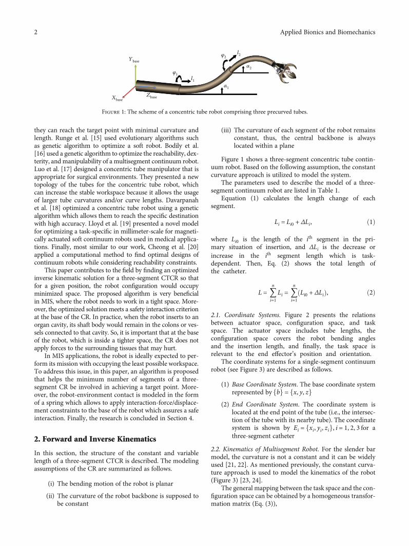
Figure 1 shows a three-segment concentric tube contin-uum robot. Based on the following assumption, the constantcurvature approach is utilized to model the system.
The parameters used to describe the model of a three-segment continuum robot are listed in Table 1.
Equation (1) calculates the length change of eachsegment.
Li = Li0 + ΔLi, ð1Þ
where Li0 is the length of the ith segment in the pri-mary situation of insertion, and ΔLi is the decrease orincrease in the ith segment length which is task-dependent. Then, Eq. (2) shows the total length ofthe catheter.
L = 〠n
i=1Li = 〠
n
i=1Li0 + ΔLið Þ, ð2Þ
2.1. Coordinate Systems. Figure 2 presents the relationsbetween actuator space, configuration space, and taskspace. The actuator space includes tube lengths, theconfiguration space covers the robot bending anglesand the insertion length, and finally, the task space isrelevant to the end effector’s position and orientation.
The coordinate systems for a single-segment continuumrobot (see Figure 3) are described as follows.
(1) Base Coordinate System. The base coordinate systemrepresented by fbg = fx, y, zg
(2) End Coordinate System. The coordinate system islocated at the end point of the tube (i.e., the intersec-tion of the tube with its nearby tube). The coordinatesystem is shown by Ei = fxi, yi, zig, i = 1, 2, 3 for athree-segment catheter
2.2. Kinematics of Multisegment Robot. For the slender barmodel, the curvature is not a constant and it can be widelyused [21, 22]. As mentioned previously, the constant curva-ture approach is used to model the kinematics of the robot(Figure 3) [23, 24].
The general mapping between the task space and the con-figuration space can be obtained by a homogeneous transfor-mation matrix (Eq. (3)),
Zbase
l1
l2
𝛼1
𝛼2
𝜑2
𝜑1
Xbase
Ybase
Figure 1: The scheme of a concentric tube robot comprising three precurved tubes.
2 Applied Bionics and Biomechanics
A2
A3
A1
B2
B3 B1
R
x
y
z
TopO´
O
Bottom
ϕ
𝛼
1
(a)
ϕ1
ϕ2
ϕ3
R
C
y
z
y1
B1
B3 B2
(b)
Figure 3: The introduced parameters in the robot: (a) the geometric display of a robot segment and (b) the display from the above of the robotplatform.
Q PV
Actuator space Configuration space Task space
Tendon lengths Arc parameters Tip position(l1, l2, l3)T (k, 𝜑, l)T (x, y, z)T
Figure 2: Mapping between joint space variables, configuration space variables, and workspace variables.
Table 1: The list of the nomenclatures used in this paper.
Symbol Definition
R The radius of curvature in the primary backbone is defined in the bending plate (the plate of X1Z1)
α The bending angle in the primary backbone is defined in the bending plate (X1Z1 plate) at the point O′.φ ∈ 0 2π½ � The orientation angle of the robot which can rotate in the xy plate
φprox, αprox Rotation and bending angles of the first part of the catheter
φmed, αmed Rotation and bending angles of the second part of the catheter
φdist, αdist Rotation and bending angles of the third part of the catheter
L0 The primary length of the primary backbone
Ai The position of the ith secondary backbone fixed in the lower platform
Bi The position of the ith secondary backbone fixed in the upper platform
O The center of the equilateral triangle made by the Ai points in the platform of x, y, zf gC The center of the equilateral triangle made by the Bi points in the platform of x1, y1, z1f gP = xc yc zc½ �T The position vector stating the center coordinate of the upper platform of each segment according to the lower platform
k Curvature
v = k φc l½ �T The configuration space vector
n The number of robot segments
R0t ∈ R3×3 The rotation matrix from the end disk coordinate system to the base coordinate system
3Applied Bionics and Biomechanics
where Rot represents the orientation of the end effector, pis the end position of the robot [25], c and s stand for cosand sin, respectively. Using the length and radius of therobot curvature shown in Figure 3, the angle α can be cal-culated using
α = lR= kl, ð4Þ
where R, l, and k are the arc length, bending radius, andcurvature, respectively. More details on how to obtainEqs. (3) and (4) could be found in [25, 26]. The forwardkinematic model of the three-segment CR can be obtainedusing
b3 T = b
0 T01 T
12 T
23 T: ð5Þ
2.3. Inverse Kinematic for a Multisegment Robot. Increaseddegrees of freedom (DOF) bring more redundancy for therobot configuration. As a result, there are no closed-formsolutions for the multisegment robot inverse kinematic.Moreover, there would be multiple solutions for the prob-lem of finding the inverse kinematics. To obtain the for-ward kinematic model, two different cases need to beconsidered for the bending angle of the distal segment[27] including θdist < 90° and 90° ≤ θdist ≤ 180°. The posi-tion of the central backbone of the catheter in the secondand third segments is achieved using
~p2 = Rot αprox� �−1 p2 − p1ð Þ,
p̂3 = Rot αmedð Þ−1 p3 − p1ð ÞRot αprox� �−1 − p2
� �,
ð6Þ
where the points PT0 = ½x0 y0 z0�, PT
1 = ½x1 y1 z1�,PT2 = ½x2 y2 z2�, and PT
3 = ½x3 y3 z3� are the catheterbase coordinate system, the intersection of the first andsecond segments, the intersection of the second and thirdsegments, and the end-plate of the third segment, respec-tively. More details can be found in [27]. Vectors ~p2 andp̂3 are local positions of the end-effector in the coordinatesystems at the base of each tube.
2.4. Optimization Problem. The optimization problem isdefined to minimize the tracking error between the
catheter tip and the corresponding target position ðPTref
= ½xref yref zref �Þ. Also, the optimized parameter wouldbe the configuration parameters including bending and rota-tion angles and insertion length of each segment. Accordingto the number of extended segments (e.g., when two or threetubes are inserted out from the overlapped tube), the cathetertip can be denoted by either ~p2 or p̂3: To form cost function,we first rearrange Eq. (6) as follows
P2:ref = P1 + Rot αprox� �
~p2:
P3:ref = P1 + Rot αprox� �
P2 + Rot αmedð ÞRot αprox� �
P̂3:ð7Þ
Next, the cost functions of the two-segment and three-segment catheter can be defined in the form of
J = γ p2:ref − p1 + Rot αprox� �
~p2� �� �T
� p2,ref − p1 + Rot αprox� �
~p2� �� �
+ α2prox + α2dist,ð8Þ
J = γ p3:ref − p1 + Rot αprox� �
p2 + Rot αmedð ÞRot αprox� �
p∧3� �� �T
� p3:ref − p1 + Rot αprox� �
p2 + Rot αmedð ÞRot αprox� �
p̂3� �� �
+ α2prox + α2med + α2dist,ð9Þ
where γ is a weighting factor.
2.5. Safe Interaction Conditions. According to Figure 4, if youwant the robot to be safely interacting with the texture, atfirst, the texture should be modeled into a spring, then, theamount of the allowed displacement for being in contact withthe robot base should be obtained. Allowed ranges of theinteraction force vary across surgical tasks. The size and fra-gility of the tissue are important parameters affecting theallowed force range.
In this paper, the following assumptions are madeaccording to the literature [28, 29].
(i) Diameter of the main coronary arteries is about4mm [30]
(ii) The maximum allowed force applicable to the textureis considered as 0.2N. The texture stiffness, at theentrance of the cavity, is considered to be k = 100N/
T =Rot p
0 1
" #=
c2φ c klð Þ − 1ð Þ + 1 −sφcφ c klð Þ − 1ð Þsφcφ c klð Þ − 1ð Þ c2φ 1 − c klð Þð Þ + c klð Þ
cφs klð Þ cφ 1 − c klð Þð Þk
sφs klð Þ sφ 1 − c klð Þð Þk
−cφs klð Þ −sφs klð Þ0 0
c klð Þ s klð Þk
0 1
26666666664
37777777775
, ð3Þ
4 Applied Bionics and Biomechanics
mwhich corresponds to 2mmdisplacement of the tis-sue which is acceptable (Eq. (10))
F = KΔxT ⇒ ΔxT = FK
= ±2mm: ð10Þ
ΔxT equals to the required displacement of Pb = ðx, y, zÞso that the catheter tip would reach to the target point.
To obtain ΔxT , first, the shape of catheter correspondingto the desired tip catheter is obtained, and then among themultiple solutions, those solutions which are meeting thesafety constraint at the point of Pb are accepted.
3. Results and Discussion
In this section, first, we simulated the kinematic modelobtained in the previous section using MATLAB.
Figure 5 demonstrates the simulation results for thethree-segment catheter. The robot configuration parameterscorresponding to the target point of the catheter tip are listedin Table 2.
Figure 6 shows the mapping between the position of therobot end-effector and the configuration space variables. Ateach iteration, the bending and rotation angles change smoothly
800
20
40
60
80
100
120
400
−40−80 −50 0
X (mm)Y (mm)
Z (m
m)
50
Figure 5: Configuration of the three-segment catheter with bending and rotation angles.
Table 2: Three-segment continuum robot bending and rotationangles.
Angles Segment 1 Segment 2 Segment 3
Bending angle (α) 63:24° 53:54° 35:58°
Rotation angle (φ) 49:80° 310:05° 178:89°
Length (mm) 73:26 36:63 76:21
1
2
Base
1
2
Pb
Catheter tip
Figure 4: The safe interaction with the texture modeled by the spring.
5Applied Bionics and Biomechanics
within ½0 π� and ½0 2π�, respectively. Step-increment equalsto 1:8° for α and 3:6° for φ. The number of the chosen samplepoints is 100. The weighting factor γ is set to 50.
3.1. Continuum Robot Workspace. In this section, the robotworkspace for a single, two, and three-segment catheter isobtained and demonstrated. The variation range of the con-figuration parameters are shown in Table 3.
As illustrated in Figures 7–12, with the increase of thenumber of robot segments, the thickness of the clouds form-ing the workspace is increasing, which reflects an enlargedaccessible space and increased precision of the three-segment catheter compared to single- or two-segment cathe-ter. Hence, one can conclude that multisegment catheters aremore appropriate choices for applications in which the cath-eter is supposed to operate in confined spaces.
3.2. Continuum Robot with Variable Length: InsertionOptimization. In this section, we consider a continuum robotwith variable length. The purpose is to optimize the robot seg-ment lengths while meeting the aforementioned constraints.The schematic of the proposed optimization algorithm is shownin Figure 13. In this diagram, first, concentric tube robot receivesthe desired point and then calculates the distance between therobot’s tip and the desired point and increases the tube’s lengthbased on the calculations. If the desired point is in the range oftube 1, only segment 1 would be involved to help the end-effector reach the target point. Otherwise, the second and thethird segments would be inserted to the workspace.
3.3. Optimization Example: A Catheter with Two Segments(No Insertion Is Allowed).We consider a two-segment cathe-
ter of 120mm length (60mm for each segment). The targetpoint is set to PT ½−47:98 − 33:92 33:90�. Using the pro-posed algorithm, as it has been shown in Figures 14 and 15,
0 10 20 30 40 50 60 70 80 90 100Sampling points
X
Y
Z
−30
−20
−10
0
10
20
30
40
Coo
rdin
ate p
oint
s of x
, y, z
axis
(mm
)
Figure 6: Changes of the robot’s final position according to the mapping of the configuration space variables.
after 2000 iterations, the optimal parameters of the robotincluding the bending and rotation angle of each segmentcan be observed in Tables 4 and 5.
According to Figure 14, the amount of the cost functionafter about 40 first iterations is approximately equal J =8:03.
We also consider the hypothetical target point in thecoordinate system PT = ½40:85 77:24 26:97� of for theoptimization of the three-segment catheter configurationspace with a general length of 120mm and a separate lengthof 40mm for each segment.
As it can also be seen in Figure 15, the amount of the costfunction, after about 60 first iterations, equals J = 6:59.
The simulation results show that the catheter accuracy toapproach the point in question is too much, also, a consider-able amount of optimization, in the first several iterations,
shows itself; as a result, it will be possible to reduce the itera-tion limit when the velocity of the process seems to be impor-tant to us.
3.4. Optimization Example: A Catheter with Two and ThreeSegments (Insertion Is Allowed). As it was mentioned, in thevariable-length catheter, considering the target point, first,the proximal segment length increases from its primarylength considered to be zero to its final length, and this sametrend for other links reports in order to approach the targetpoint.
The three-segment catheter will have the same length foreach segment which is 40mm has been used, so as to simulatehow to access the variable-length catheter.
We consider the target point at P =½34:85 17:11 62:22�T . After 2000 iterations, and after
−100−100−50 −50
00
X (mm)Y (mm)
5050
1000
20
40
60
80
100
120
Z (m
m)
100
Figure 8: One-segment catheter workspace in 3D.
−100
100
80
60
40
20
0
120
−80 −60 −40 −20 0X (mm)
Z (m
m)
20 40 60 80 100
Figure 9: Two-segment catheter workspace in 2D.
7Applied Bionics and Biomechanics
optimization using the genetic algorithm, and also using thecost function of Eq. (8), the amount of the shown responsein the 2016 Matlab will be in the form of Table 6. Accordingto these optimal parameters, the order of error is 0:01mm fortwo segment catheter which is small in comparison to threesegment catheter that has an error greater than 1mm. There-fore, the variable-length catheter will use two-segment of itsinner parts in order to approach the desirable point, and thissame result has been shown in the last row of the first col-umn. Also, the optimization amount of the two-segment costfunction has been obtained to be the number of J = 1:1032that is an appropriate amount for tracking the target point.
3.5. Optimization of the Three-Segment Catheter withVariable Length Having the Safe Interacting with FragileStructures like Texture. We choose first the hypotheticalpoint of P = ½30:16 25:59 65:96�T as the target point, foroptimization of the three-segment catheter configuration
space with variable length. In the simulations, we considerfirst the position of the robot tip at the entrance of the cavityin the form of the coordinate system of B = ½0 0 10�T . Atfirst, the optimization results for the point in question areshown in Table 7 without the safe interaction with the fragilestructures like texture. If dB < ΔxT , the obtained positionand the parameters related to this position are correct, ifnot, another response is chosen.
According to these optimal parameters, the order of erroris 0:01mm for a two-segment catheter which is small in com-parison to three segment catheter that has an error greaterthan 1mm. Regarding the error amount, for each segment,the desirable link will be the second link. Also, the amountof the cost function for the two-segment of the variable-length catheter will be equal to 1:4539.
As you can see in Table 8, for the catheter safe interactingwith fragile structures like texture, according to the Eqs. (8)and (9), at first, we obtained the safe limitation constraint
−100−100 −50 00
0
20
40
60
80
100
120
100
Y (mm)X (mm)
Z (m
m)
50 100
Figure 10: Two-segment catheter workspace in 3D.
−100
100
80
60
40
20
0
120
−80 −60 −40 −20 0X (mm)
Z (m
m)
20 40 60 80 100
Figure 11: Three-segment catheter workspace in 2D.
8 Applied Bionics and Biomechanics
100−100
0
20
40
60
80
100
120
−100−50
050
X (mm)Y (mm)
Z (m
m)
−500
50100
Figure 12: Three-segment catheter workspace in 3D.
Start
Get the target point
The distance from tip's catheter is calculated
If dist < L1
Finish
Compare the answers A, B, C and give the optimal answer
If L1< dist < L1 + L2
Compare the answers A, B and give the optimal answer
If L1 + L2 < dist < L1 + L2 + L3
Yes
No
YesNo
No
A) Find the optimal solution by solving the inverse kinematics code of a single-segment robotB) Find the optimal solution by solving the inverse kinematics code of a two-segment robotC) Find the optimal solution by solving the inverse kinematics code of a three-segment robot
A) Find the optimal solution by solving the inverse kinematics code of a two-segment robotB) Find the optimal solution by solving the inverse kinematics code of a three-segment robot
A) Find the optimal solution by solving the inverse kinematics code of athree segment robot
dist = x2 + y2 + z2
Figure 13: Flow chart for finding an optimal inverse kinematics.
9Applied Bionics and Biomechanics
for interacting with fragile structures like texture. Consider-ing the two mentioned conditions, we take into considerationthe maximum amount of the allowed force which is appliedto the texture to be 0:2N, and also the stiffness to be 100, atthe entrance of the cavity. According to Eq. (10), the dis-placement amount at the contact point with the texture willbe obtained as ±2mm. Now, after required iterations from
the population in the algorithm, in each of the robot seg-ments, the correct link for approaching the chosen targetpoint and the angle amounts of the catheter are obtained inthe case that the distance amount of the robot is less than2mm.
0
15
10
5C
ost
05 10 15 20 25
Iteration30 35 40 45 50
× 104
Figure 14: Genetic algorithm for best fitness target point in two-segment catheter.
0
3000
2000
1000
Cos
t
05 10 15 20 25
Iteration30 35 40 45 7055 60 6550
Figure 15: Genetic algorithm for best fitness target point in three-segment catheter.
Table 4: Optimized results for reaching target point.
Sectionnumber
Optimalbending angle
(degree)
Optimalrotation angle
(degree)
Reachingpoint(mm)
Error(mm)
1 99.80 195.42
X: -40.81Y : -33.64Z: 33.73
X:0.17Y :0.28Z:0.17
2 88.57 324.01
Table 5: Optimized results for reaching target point.
Sectionnumber
Optimalbending angle
(degree)
Optimalrotation angle
(degree)
Reachingpoint(mm)
Error(mm)
1 98.34 53.36X: 40.86Y : 77.27Z: 26.97
X:0.01Y :0.03Z: 0
2 99.33 151.98
3 43.78 73.15
Table 6: Optimized results for three-segment catheter with variablelength.
Two-segment Tracked point Three-segment Tracked point
According to the obtained error amount from the hypo-thetical target point and the tracked point in the three-segment catheter, it can be concluded that the three-segmentcatheter has an undesirable tracking for approaching the targetpoint, and also according to the obtained points in the tablesecond column, and the little error amount the catheter willuse two segments from its inner parts for approaching to thedesired point.
Also, the optimized cost function amount of the two-segment catheter is obtained to be 2.8294 which is anappropriate amount for tracking the target point. In the lastrow of the first column, the allowed displacement amountat the contact point with the texture has been gained whichis equal to dB = 1:1641mm, which is less than the indicatedamount of 2mm. This shows the catheter’s safe interactionwith the texture.
4. Conclusion
In this paper, the optimization and kinematic model of thecontinuum robot target tracking have been surveyed in twostates of constant and variable lengths. To do this, themethod of the constant curvature was applied, consideringthe bending of each segment of the robot in the Platform,extracting the forward kinematics for constant and variablelengths, and using inverse kinematics for the robot. Thisrobot’s being redundant has caused it not to require theclosed-form solution for its inverse kinematic. For this rea-son, optimization and numerical solving methods have beenused for tracking the target by the robot. Adding the possibil-ity of the robot length change, the robot workspace andredundancy are increased, and we can use it to provide moredexterity. As it was done in this research, whereas the lengthchanges of each one of the segments are influenced using theoffered algorithm as a variable of the configuration space forapproaching the target point, it is possible to use it as a toolfor better control of the robot. Also, the robot movementlimit will be more appropriate for environments like the ves-sels. In this paper, the results of the forward kinematics partsconfirm the results of the inverse kinematics parts, and viceversa, which indicates the accuracy of the model. Also, forthe part of the optimization of the multisegment catheter,the results also indicate the model appropriate accuracy intracking the giving points for performing endovascular sur-gery. The average distal end positioning error is less than1% for each segment of the catheter, which is an acceptable
error for most real-time surgeries. In the final part, regardingforce imposed onto the texture, and also the stiffness, theallowed distance amount with the texture causes the safeinteraction. The implementation of the secure interactionwith the texture and the trajectory results indicate the cathe-ter has an accurate application in the medical procedure.Future works focusing on the addition of more constraints,and optimization of the distinguished constraints of the costfunction, try to lessen the tracking errors and to improve thestability of the existing catheter. Also, tracking a certain pathconcerning the safe interaction with the texture for the cath-eter will be carried out.
Data Availability
The MATLAB code data used to support the findings of thisstudy are available from the corresponding author uponrequest.
Conflicts of Interest
The authors declare that they have no conflicts of interest.
References
[1] S. Norouzi-Ghazbi and F. Janabi-Sharifi, “Dynamic modelingand system identification of internally actuated, small-sizedcontinuum robots,” Mechanism and Machine Theory,vol. 154, article 104043, 2020.
[2] D. Trivedi, C. D. Rahn, W. M. Kier, and I. D. Walker, “Softrobotics: biological inspiration, state of the art, and futureresearch,”Applied Bionics and Biomechanics, vol. 5, no. 3, Arti-cle ID 520417, p. 117, 2008.
[3] S. Norouzi-Ghazbi, A. Mehrkish, I. Abdulhafiz, T. Abbasi-Hashemi, A. Mahdi, and F. Janabi-Sharifi, “Design and exper-imental evaluation of an automated catheter operating sys-tem,” Artificial Organs, vol. 45, no. 6, pp. E171–E186, 2021.
[4] Y. Ganji, F. Janabi-Sharifi, and A. N. Cheema, “Robot-assistedcatheter manipulation for intracardiac navigation,” Interna-tional Journal of Computer Assisted Radiology and Surgery,vol. 4, no. 4, pp. 307–315, 2009.
[5] M. Dehghani and S. A. A. Moosavian, “Modeling and controlof a planar continuum robot,” in 2011 IEEE/ASME Interna-tional Conference on Advanced Intelligent Mechatronics(AIM), pp. 966–971, Budapest, Hungary, 2011.
[6] D. Trivedi, A. Lotfi, and C. D. Rahn, “Geometrically exactdynamic models for soft robotic manipulators,” in 2007IEEE/RSJ International Conference on Intelligent Robots andSystems, pp. 1497–1502, San Diego, USA, 2007.
[7] M. T. Chikhaoui, S. Lilge, S. Kleinschmidt, and J. Burgner-Kahrs, “Comparison of modeling approaches for a tendonactuated continuum robot with three extensible segments,”IEEE Robotics and Automation Letters, vol. 4, no. 2, pp. 989–996, 2019.
[8] H. Cheng, H. Liu, X. Wang, and B. Liang, “Approximate piece-wise constant curvature equivalent model and their applica-tion to continuum robot configuration estimation,” in 2020IEEE International Conference on Systems, Man, and Cyber-netics (SMC), pp. 1929–1936, Toronto, Canada, 2020.
Table 8: Optimized results for three-segment catheter with variablelength with interaction with fragile structures like texture.
Two-segment Tracked point Three-segment Tracked point
[9] T. da Veiga, J. H. Chandler, P. Lloyd et al., “Challenges of con-tinuum robots in clinical context: a review,” Progress in Bio-medical Engineering, vol. 2, no. 3, article 032003, 2020.
[10] L. A. Lyons, R. J. Webster, and R. Alterovitz, “Planning activecannula configurations through tubular anatomy,” in 2010IEEE International Conference on Robotics and Automation,pp. 2082–2087, Anchorage, AK, USA, 2010.
[11] R. J. Webster, J. M. Romano, and N. J. Cowan, “Kinematicsand calibration of active cannulas,” in 2008 IEEE InternationalConference on Robotics and Automation, pp. 3888–3895, Pas-adena, CA, USA, 2008.
[12] S. Neppalli, M. A. Csencsits, B. A. Jones, and I. Walker, “A geo-metrical approach to inverse kinematics for continuummanipulators,” in 2008 IEEE/RSJ International Conference onIntelligent Robots and Systems, pp. 3565–3570, Nice, France,2008.
[13] T. Anor, J. R. Madsen, and P. Dupont, “Algorithms for designof continuum robots using the concentric tubes approach: aneurosurgical example,” in 2011 IEEE international conferenceon robotics and automation, pp. 667–673, Shanghai, China,2011.
[14] C. Bedell, J. Lock, A. Gosline, and P. E. Dupont, “Design opti-mization of concentric tube robots based on task and anatom-ical constraints,” in 2011 IEEE international conference onrobotics and automation, pp. 398–403, Shanghai, China, 2011.
[15] G. Runge, J. Peters, and A. Raatz, “Design optimization of softpneumatic actuators using genetic algorithms,” in 2017 IEEEInternational Conference on Robotics and Biomimetics(ROBIO), pp. 393–400, Macau, Macao, 2017.
[16] D. M. Bodily, T. F. Allen, and M. D. Killpack, “Multi-objectivedesign optimization of a soft, pneumatic robot,” in 2017 IEEEInternational Conference on Robotics and Automation (ICRA),pp. 1864–1871, Singapore, 2017.
[17] K. A. X. J. Luo, T. Looi, S. Sabetian, and J. Drake, “Designingconcentric tube manipulators for stability using topology opti-mization,” in 2018 IEEE/RSJ International Conference on Intel-ligent Robots and Systems (IROS), pp. 1764–1769, Madrid,Spain, 2018.
[18] D. Atoosa, K. Mostafa, M. Amin, and K. SE, “Optimization ofconcentric tube continuum robot based on accuracy and over-all length of the robot via genetic algorithm,” Annals of Robot-ics and Automation, vol. 4, no. 1, pp. 007–012, 2020.
[19] P. Lloyd, G. Pittiglio, J. H. Chandler, and P. Valdastri, “Opti-mal design of soft continuum magnetic robots under follow-the-leader shape forming actuation,” in 2020 InternationalSymposium onMedical Robotics (ISMR), pp. 111–117, Atlanta,GA, USA, 2020.
[20] H. Cheong, M. Ebrahimi, and T. R. Duggan, “Optimal designof continuum robots with reachability constraints,” IEEERobotics and Automation Letters, vol. 6, no. 2, pp. 3902–3909, 2021.
[21] J. Liu, Y. Mei, and X. Dong, “Post-buckling behavior of adouble-hinged rod under self-weight,” Acta Mechanica SolidaSinica, vol. 26, no. 2, pp. 197–204, 2013.
[22] J. L. Liu, Y. Mei, R. Xia, and W. L. Zhu, “Large displacement ofa static bending nanowire with surface effects,” Physica E: Low-dimensional systems and Nanostructures, vol. 44, no. 10,pp. 2050–2055, 2012.
[23] B. A. Jones and I. D. Walker, “Kinematics for multisectioncontinuum robots,” IEEE Transactions on Robotics, vol. 22,no. 1, pp. 43–55, 2006.
[24] R. J. Webster III and B. A. Jones, “Design and kinematicmodeling of constant curvature continuum robots: a review,”The International Journal of Robotics Research, vol. 29,no. 13, pp. 1661–1683, 2010.
[25] Y. Tian, M. Luan, X. Gao, W. Wang, and L. Li, “Kinematicanalysis of continuum robot consisted of driven flexible rods,”Mathematical Problems in Engineering, vol. 2016, Article ID6984194, 7 pages, 2016.
[26] Y. Bailly, Y. Amirat, and G. Fried, “Modeling and control of acontinuum style microrobot for endovascular surgery,” IEEETransactions on Robotics, vol. 27, no. 5, pp. 1024–1030, 2011.
[27] J. H. Wiest and G. D. Buckner, “Path optimization and controlof a shape memory alloy actuated catheter for endocardialradiofrequency ablation,” Robotics and Autonomous Systems,vol. 65, pp. 88–97, 2015.
[28] S. Hasanzadeh, Modeling, Force Estimation and Control ofSteerable Catheters for Robot-Assisted Intra-Cardiac Naviga-tion [PhD dissertation], Ryerson University, 2015.
[29] J. Back, T. Manwell, R. Karim, K. Rhode, K. Althoefer, andH. Liu, “Catheter contact force estimation from shape detec-tion using a real-time Cosserat rod model,” in 2015 IEEE/RSJInternational Conference on Intelligent Robots and Systems(IROS), pp. 2037–2042, Hamburg, Germany, 2015.
[30] J. T. Dodge Jr., B. G. Brown, E. L. Bolson, and H. T. Dodge,“Lumen diameter of normal human coronary arteries. Influ-ence of age, sex, anatomic variation, and left ventricular hyper-trophy or dilation,” Circulation, vol. 86, no. 1, pp. 232–246,1992.


![Inverse Kinematics and Gaze Stabilization for the Rochester ......3 Inverse Kinematics 3.1 Inverse Kinematics: O,A,T from TOOL The mathematics in [Brown and Rimey, 1988] Section 9](https://static.documents.pub/doc/80x56/60be15e583990e1ab8600327/inverse-kinematics-and-gaze-stabilization-for-the-rochester-3-inverse-kinematics.jpg)


