IOSR Journal of Electrical and Electronics Engineering (IOSR-JEEE) e-ISSN: 2278-1676,p-ISSN: 2320-3331, Volume 10, Issue 2 Ver. III (Mar – Apr. 2015), PP 33-45 www.iosrjournals.org DOI: 10.9790/1676-10233345 www.iosrjournals.org 33 | Page Inverted Sine Pulse Width Modulation Approaches for Power Quality Enhancement with Custom Power Devices T.Sridevi #1 ≠1 Assistant professor, Sri Sairam Institute of Technology, Chennai,Tamilnadu Abstract: This paper addresses the application of a new Pulse-Wide Modulation (PWM) technique called inverted-sine PWM (ISPWM). These technique can be used to control Voltage Source Converters (VSC) of custom power devices which provide valuable supply to customers in low voltage distribution networks. The ISPWM technique generates lower voltage Total Harmonic Distortion (THD) in comparison with conventional Sinusoidal PWM (SPWM) technique. The proposed switching technique has been implemented on Distribution Static Compensator (DSTATCOM) and Dynamic Voltage Restorer (DVR). Simulation results with MATLAB Simulink show the effectiveness of the proposed switching techniques in the reduction of Total Harmonic Distortion (THD) than conventional sine PWM technique. Keywords: PWM, Power Quality, Harmonics, VSC, D-STATCOM, DVR, Custom Power, Voltage Sag. I. Introduction One of the most common power quality problems is Voltage sag. Voltage sag is a reduction in the RMS voltage in the range of 0.1 to 0.9 p.u. (retained) for duration greater than half a mains cycle and less than 1 minute. Voltage sags caused by faults, increased load demand and transitional events such as large motor starting. There are different ways to mitigate voltage dips in distribution systems. Fig 1 waveform representing voltage sag,swell, impulse voltage A custom power specification may include provision for (i) no power interruption (ii) Tight Voltage regulation including short duration sags or swells (iii) Low harmonic Voltages and (iv) Acceptance of fluctuating and non linear loads without effect on terminal voltage. These devices are connected either in shunt or in series or in combination of both series and shunt. The series-connected device is dynamic voltage restorer (DVR) that is to inject a voltage of desired amplitude, frequency and phase between the PCC and the load in series with the grid voltage. The shunt-connected device is distribution static compensator (DSTATCOM) which is to dynamically inject a current of desired amplitude, frequency and phase into the grid. Power electronic converters which are main component in custom power devices introduce harmonics due to switching operation of thyristor. To reduce harmonics for power quality enhancement , PWM techniques called inverted sine PWM(ISPWM),Trapezoidal inverted sine PWM(TISPWM) and Sawtooth inverted sine PWM(SISPWM) techniques have been developed by using MATLAB simulink. These results are compared with sine PWM.
Transcript
IOSR Journal of Electrical and Electronics Engineering (IOSR-JEEE)
Inverted Sine Pulse Width Modulation Approaches for Power
Quality Enhancement with Custom Power Devices
T.Sridevi
#1
≠1Assistant professor, Sri Sairam Institute of Technology, Chennai,Tamilnadu
Abstract: This paper addresses the application of a new Pulse-Wide Modulation (PWM) technique called inverted-sine PWM (ISPWM). These technique can be used to control Voltage Source Converters (VSC) of
custom power devices which provide valuable supply to customers in low voltage distribution networks. The
ISPWM technique generates lower voltage Total Harmonic Distortion (THD) in comparison with conventional
Sinusoidal PWM (SPWM) technique. The proposed switching technique has been implemented on Distribution
Static Compensator (DSTATCOM) and Dynamic Voltage Restorer (DVR). Simulation results with MATLAB
Simulink show the effectiveness of the proposed switching techniques in the reduction of Total Harmonic
Distortion (THD) than conventional sine PWM technique.
Keywords: PWM, Power Quality, Harmonics, VSC, D-STATCOM, DVR, Custom Power, Voltage Sag.
I. Introduction One of the most common power quality problems is Voltage sag. Voltage sag is a reduction in the
RMS voltage in the range of 0.1 to 0.9 p.u. (retained) for duration greater than half a mains cycle and less than 1
minute. Voltage sags caused by faults, increased load demand and transitional events such as large motor
starting. There are different ways to mitigate voltage dips in distribution systems.
Fig 1 waveform representing voltage sag,swell, impulse voltage
A custom power specification may include provision for (i) no power interruption (ii) Tight Voltage
regulation including short duration sags or swells (iii) Low harmonic Voltages and (iv) Acceptance of
fluctuating and non linear loads without effect on terminal voltage. These devices are connected either in shunt
or in series or in combination of both series and shunt. The series-connected device is dynamic voltage restorer
(DVR) that is to inject a voltage of desired amplitude, frequency and phase between the PCC and the load in
series with the grid voltage. The shunt-connected device is distribution static compensator (DSTATCOM)
which is to dynamically inject a current of desired amplitude, frequency and phase into the grid. Power
electronic converters which are main component in custom power devices introduce harmonics due to switching
operation of thyristor. To reduce harmonics for power quality enhancement , PWM techniques called inverted
sine PWM(ISPWM),Trapezoidal inverted sine PWM(TISPWM) and Sawtooth inverted sine PWM(SISPWM)
techniques have been developed by using MATLAB simulink. These results are compared with sine PWM.
Inverted Sine Pulse Width Modulation Approaches for Power Quality Enhancement with ….
II. Custom Power Devices 2.1 Classification of custom power devices
Fig 2 Custom Power Distribution System
Custom power devices can be classified into two major categories. One is network configuring type
and the other is compensating type. The former changes the configuration of the power system network for
power quality enhancement.SSCL (Solid State Current Limiter), SSCB (Solid State Circuit Breaker) and SSTS
(Solid State Transfer Switch) are the most representative in this category.
The compensating type devices are used for active filtering, load balancing, power factor correction
and voltage regulation. The family of compensating devices include DSTATCOM (Distribution Static
compensator), DVR (Dynamic voltage restorer) and Unified power quality conditioner (UPQC) .DSTATCOM
has a similar structure and function to STATCOM in the transmission system.DSTATCOM is connected in shunt with the power system.DVR is a series connected device that injects a rapid series voltage to compensate
the supply voltage.
Fig 2.1 Configuration of Custom Power Devices
III. Distribution Static Synchronous Compensator (D-Statcom) 3.1 Basic Principle of DSTATCOM
A DSTATCOM is a controlled reactive source, which includes a Voltage Source Converter (VSC) and
a DC link capacitor connected in shunt, capable of generating and/or absorbing reactive power. The operating
principles of a DSTATCOM are based on the exact equivalence of the conventional rotating synchronous compensator.
.
Fig.3.1 Basic structure of DSTAT COM
The AC terminals of the VSC are connected to the Point of Common Coupling (PCC) through an
inductance, which could be a filter inductance or the leakage inductance of the coupling transformer, as shown
in figure 3.1. The DC side of the converter is connected to a DC capacitor, which carries the input ripple current
of the converter and is the main reactive energy storage element. This capacitor could be charged by a battery
Inverted Sine Pulse Width Modulation Approaches for Power Quality Enhancement with ….
source, or could be recharged by the converter itself.. For a DSTATCOM used for voltage regulation at the
PCC, the compensation should be such that the supply currents should lead the supply voltages. The control
strategies are applied with DSTATCOM for harmonic mitigation.
3.2. Basic Configuration and Operation of D-STATCOM
The D-STATCOM is a three-phase and shunt connected power electronics based device. It is
connected near the load at the distribution systems. The major components of a DSTATCOM are shown in
figure 3.2. It consists of a dc capacitor, three-phase inverter (IGBT, thyristor) module, ac filter, coupling
transformer and a control strategy. The basic electronic block of the D-STATCOM is the voltage-sourced
inverter that converts an input dc voltage into a three-phase output voltage at fundamental frequency.
Fig 3.2 Basic building blocks of D-STATCOM
In the figure 3.2,the controller of the D-STATCOM is used to operate the inverter in such a way that the phase angle between the inverter voltage and the line voltage is dynamically adjusted so that the D-
STATCOM generates or absorbs the desired VAR at the point of connection. The phase of the output voltage of
the thyristor-based inverter is controlled in the same way as the distribution system voltage, Vs.
IV. Dynamic Voltage Restorer (DVR) The DVR is a powerful controller commonly used for voltage sags mitigation. The DVR employs the
same blocks as the D-STATCOM, but in this application the coupling transformer is connected in series with
the AC system
. Fig.4 Schematic representation of DVR
The VSC generates a three-phase AC output voltage which can be controlled in phase and magnitude.
These voltages are injected into the AC distribution system in order to maintain the load voltage at the desired
voltage level.
Features of DVR
• Voltages sag and swell compensation.
• Line voltage harmonics compensation. • Reduction of transients in voltage.
• Fault current limitations.
4.1 Principle of DVR Operation
A DVR is a solid state power electronics switching device consisting of either GTO or IGBT, a
capacitor bank as an energy storage device and injection transformers. It is linked in series between a
distribution system and a load that shown in figure. The basic idea of the DVR is to inject a controlled voltage
Inverted Sine Pulse Width Modulation Approaches for Power Quality Enhancement with ….
generated by a forced commutated inverter in series to the bus voltage by means of an injection transformer. A
DC to AC inverter regulates this voltage by using sinusoidal PWM technique.. However, when the voltage sag
occurs in distribution system, the DVR control system calculates and synthesizes the voltage required to preserve output voltage to the load by injecting a controlled voltage with a certain magnitude and phase angle
into the distribution system to the critical load.
Fig.4.1 Principle of DVR System
V. Basic Arrangement of DVR
The DVR mainly consists of the following components.
i. An injection transformer
ii. DC charging unit
iii. Storage devices iv. A voltage source converter(VSC)
v. Harmonic filter
vi. A control and protection system
Fig.5. Schematic diagram of DVR
5.1 Series Voltage Injection Transformers:
In a three-phase system, either three single-phase transformer units or one three phase transformer unit
can be used for voltage injection purpose .The injection transformer comprises of two side voltages namely the
high voltage side and low voltage side. Normally the high voltage side of the injection transformer is connected
in series to the distribution system while power circuit of the DVR can be connected at the low voltage side. The
basic function of the injection transformer is to increase the voltage supplied by the filtered VSI output to the desired level while isolating the DVR circuit from the distribution network.
5.2 Energy Storage:
The DVR needs real power for compensation purposes during voltage disturbances in the distribution
system. In this case the real power of the DVR must be supplied by energy storage when the voltage
disturbances exit. The energy storage such as a battery is responsible to supply an energy source in DC form.
Energy storage consists of two types form. One using stored energy to supply the delivered power and the other
having no significant internal energy storage but instead energy is taken from the faulted grid supply during the
sags. A shunt–converter or the rectifier is the main sources of the direct energy storage which is supplied to
DVR. Flywheels, batteries, superconducting magnetic energy storage (SMES) and super capacitors can be used
as energy storage devices.
5.3 LC Filter
Basically filter unit consists of inductor (L) and capacitor (C). In DVR, filters are used to convert the
inverted PWM waveform into a sinusoidal waveform. This can be achieved by eliminating the unwanted
harmonic components generated by the VSI action. Higher orders harmonic components distort the
Inverted Sine Pulse Width Modulation Approaches for Power Quality Enhancement with ….
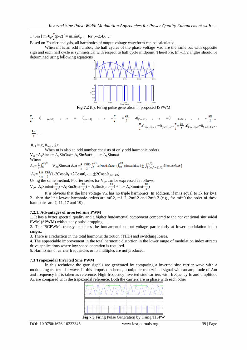
Based on Fourier analysis, all harmonics of output voltage waveform can be calculated. When mf is an odd number, the half cycles of the phase voltage Vao are the same but with opposite
sign and each half cycle is symmetrical with respect to half cycle midpoint. Therefore, (mf-1)/2 angles should be
determined using following equations
Fig.7.2 (b). Firing pulse generation in proposed ISPWM
It is obvious that the line voltage Vab has no triple harmonics. In addition, if mfis equal to 3k for k=1, 2…then the line lowest harmonic orders are mf-2, mf+2, 2mf-2 and 2mf+2 (e.g., for mf=9 the order of these
harmonics are 7, 11, 17 and 19).
7.2.1. Advantages of inverted sine PWM
1. It has a better spectral quality and a higher fundamental component compared to the conventional sinusoidal
PWM (SPWM) without any pulse dropping.
2. The ISCPWM strategy enhances the fundamental output voltage particularly at lower modulation index
ranges.
3. There is a reduction in the total harmonic distortion (THD) and switching losses.
4. The appreciable improvement in the total harmonic distortion in the lower range of modulation index attracts
drive applications where low speed operation is required. 5. Harmonics of carrier frequencies or its multiples are not produced.
7.3 Trapezoidal Inverted Sine PWM
In this technique the gate signals are generated by comparing a inverted sine carrier wave with a
modulating trapezoidal wave. In this proposed scheme, a unipolar trapezoidal signal with an amplitude of Am
and frequency fm is taken as reference. High frequency inverted sine carriers with frequency fc and amplitude
Ac are compared with the trapezoidal reference. Both the carriers are in phase with each other
Fig 7.3 Firing Pulse Generation by Using TISPW
Inverted Sine Pulse Width Modulation Approaches for Power Quality Enhancement with ….