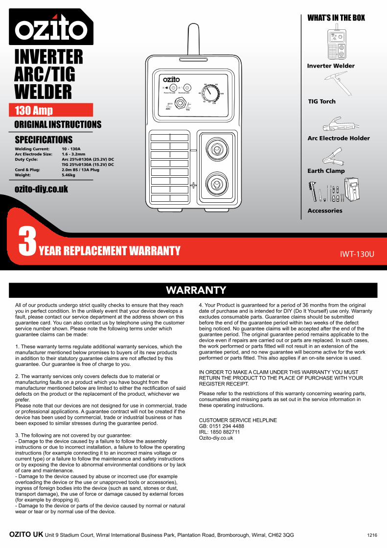
INVERTER ARC/TIG WELDER 130 Amp ORIGINAL INSTRUCTIONS SPECIFICATIONS Welding Current: 10 - 130A Arc Electrode Size: 1.6 - 3.2mm Duty Cycle: Arc 25%@130A (25.2V) DC TIG 25%@130A (15.2V) DC Cord & Plug: 2.0m BS / 13A Plug Weight: 5.46kg IWT-130U WHAT’S IN THE BOX Accessories Inverter Welder TIG Torch Earth Clamp Arc Electrode Holder WARRANTY 1216 5 6 5 6 ozito-diy.co.uk OZITO UK Unit 9 Stadium Court, Wirral International Business Park, Plantation Road, Bromborough, Wirral, CH62 3QG All of our products undergo strict quality checks to ensure that they reach you in perfect condition. In the unlikely event that your device develops a fault, please contact our service department at the address shown on this guarantee card. You can also contact us by telephone using the customer service number shown. Please note the following terms under which guarantee claims can be made: 1. These warranty terms regulate additional warranty services, which the manufacturer mentioned below promises to buyers of its new products in addition to their statutory guarantee claims are not affected by this guarantee. Our guarantee is free of charge to you. 2. The warranty services only covers defects due to material or manufacturing faults on a product which you have bought from the manufacturer mentioned below are limited to either the rectification of said defects on the product or the replacement of the product, whichever we prefer. Please note that our devices are not designed for use in commercial, trade or professional applications. A guarantee contract will not be created if the device has been used by commercial, trade or industrial business or has been exposed to similar stresses during the guarantee period. 3. The following are not covered by our guarantee: - Damage to the device caused by a failure to follow the assembly instructions or due to incorrect installation, a failure to follow the operating instructions (for example connecting it to an incorrect mains voltage or current type) or a failure to follow the maintenance and safety instructions or by exposing the device to abnormal environmental conditions or by lack of care and maintenance. - Damage to the device caused by abuse or incorrect use (for example overloading the device or the use or unapproved tools or accessories), ingress of foreign bodies into the device (such as sand, stones or dust, transport damage), the use of force or damage caused by external forces (for example by dropping it). - Damage to the device or parts of the device caused by normal or natural wear or tear or by normal use of the device. 4. Your Product is guaranteed for a period of 36 months from the original date of purchase and is intended for DIY (Do It Yourself) use only. Warranty excludes consumable parts. Guarantee claims should be submitted before the end of the guarantee period within two weeks of the defect being noticed. No guarantee claims will be accepted after the end of the guarantee period. The original guarantee period remains applicable to the device even if repairs are carried out or parts are replaced. In such cases, the work performed or parts fitted will not result in an extension of the guarantee period, and no new guarantee will become active for the work performed or parts fitted. This also applies if an on-site service is used. IN ORDER TO MAKE A CLAIM UNDER THIS WARRANTY YOU MUST RETURN THE PRODUCT TO THE PLACE OF PURCHASE WITH YOUR REGISTER RECEIPT. Please refer to the restrictions of this warranty concerning wearing parts, consumables and missing parts as set out in the service information in these operating instructions. CUSTOMER SERVICE HELPLINE GB: 0151 294 4488 IRL: 1850 882711 Ozito-diy.co.uk
OZITO UK Unit 9 Stadium Court, Wirral International Business Park, Plantation Road, Bromborough, Wirral, CH62 3QG
All of our products undergo strict quality checks to ensure that they reach you in perfect condition. In the unlikely event that your device develops a fault, please contact our service department at the address shown on this guarantee card. You can also contact us by telephone using the customer service number shown. Please note the following terms under which guarantee claims can be made:
1. These warranty terms regulate additional warranty services, which the manufacturer mentioned below promises to buyers of its new products in addition to their statutory guarantee claims are not affected by this guarantee. Our guarantee is free of charge to you.
2. The warranty services only covers defects due to material or manufacturing faults on a product which you have bought from the manufacturer mentioned below are limited to either the rectification of said defects on the product or the replacement of the product, whichever we prefer. Please note that our devices are not designed for use in commercial, trade or professional applications. A guarantee contract will not be created if the device has been used by commercial, trade or industrial business or has been exposed to similar stresses during the guarantee period.
3. The following are not covered by our guarantee: - Damage to the device caused by a failure to follow the assembly instructions or due to incorrect installation, a failure to follow the operating instructions (for example connecting it to an incorrect mains voltage or current type) or a failure to follow the maintenance and safety instructions or by exposing the device to abnormal environmental conditions or by lack of care and maintenance. - Damage to the device caused by abuse or incorrect use (for example overloading the device or the use or unapproved tools or accessories), ingress of foreign bodies into the device (such as sand, stones or dust, transport damage), the use of force or damage caused by external forces (for example by dropping it). - Damage to the device or parts of the device caused by normal or natural wear or tear or by normal use of the device.
4. Your Product is guaranteed for a period of 36 months from the original date of purchase and is intended for DIY (Do It Yourself) use only. Warranty excludes consumable parts. Guarantee claims should be submitted before the end of the guarantee period within two weeks of the defect being noticed. No guarantee claims will be accepted after the end of the guarantee period. The original guarantee period remains applicable to the device even if repairs are carried out or parts are replaced. In such cases, the work performed or parts fitted will not result in an extension of the guarantee period, and no new guarantee will become active for the work performed or parts fitted. This also applies if an on-site service is used.
IN ORDER TO MAKE A CLAIM UNDER THIS WARRANTY YOU MUST RETURN THE PRODUCT TO THE PLACE OF PURCHASE WITH YOUR REGISTER RECEIPT.
Please refer to the restrictions of this warranty concerning wearing parts, consumables and missing parts as set out in the service information in these operating instructions.
ONLINE MANUALScan this QR Code with your mobile device to take you to the online manual.
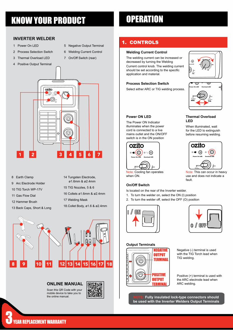
1 Power On LED
2 Process Selection Switch
3 Thermal Overload LED
4 Positive Output Terminal
5 Negative Output Terminal
6 Welding Current Control
7 On/Off Switch (rear)
INVERTER WELDER
KNOW YOUR PRODUCT
1. CONTROLS
Welding Current ControlThe welding current can be increased or decreased by turning the WeldingCurrent control knob. The welding current should be set according to the specific application and material.
NOTE: Fully insulated lock-type connectors should be used with the Inverter Welders Output Terminals
8 Earth Clamp
9 Arc Electrode Holder
10 TIG Torch WP-17V
11 Gas Flow Dial
12 Hammer Brush
13 Back Caps, Short & Long
14 Tungsten Electrode, ø1.6mm & ø2.4mm
15 TIG Nozzles, 5 & 6
16 Collets ø1.6mm & ø2.4mm
17 Welding Mask
18. Collet Body, ø1.6 & ø2.4mm
Process Selection SwitchSelect either ARC or TIG welding process.
Power ON LEDThe Power ON Indicator illuminates when the power cord is connected to a live mains outlet and the ON/OFF switch is in the ON position
Thermal Overload LEDWhen illuminated, wait for the LED to extinguish before resuming welding.
On/Off SwitchIs located on the rear of the Inverter welder.1. To turn the welder on, select the ON (I) position2. To turn the welder off, select the OFF (O) position
0 / OFF
I / ON
POSITIVE OUTPUT TERMINAL
NEGATIVE OUTPUT TERMINAL
Output TerminalsNegative (-) terminal is used with the TIG Torch lead when TIG welding.
Positive (+) terminal is used with the ARC electrode lead when ARC welding.
5 65 6
Note: This can occur in heavy use and does not indicate a fault.
Note: Cooling fan operates when ON.
OPERATION
2. ARC WELDING ASSEMBLY 3. ARC WELDING
Slag
Slag is refuse left around the weld after welding, this should only be removed after the weld has cooled down and is no longer glowing. Face shield must be worn during removal of slag.
4. Install thin (uncoated) end of Electrode into the arc electrode holder.
5. Attach the Earth Clamp to the work piece ensuring area is free from paint or dirt so that there is a good electrical connection.
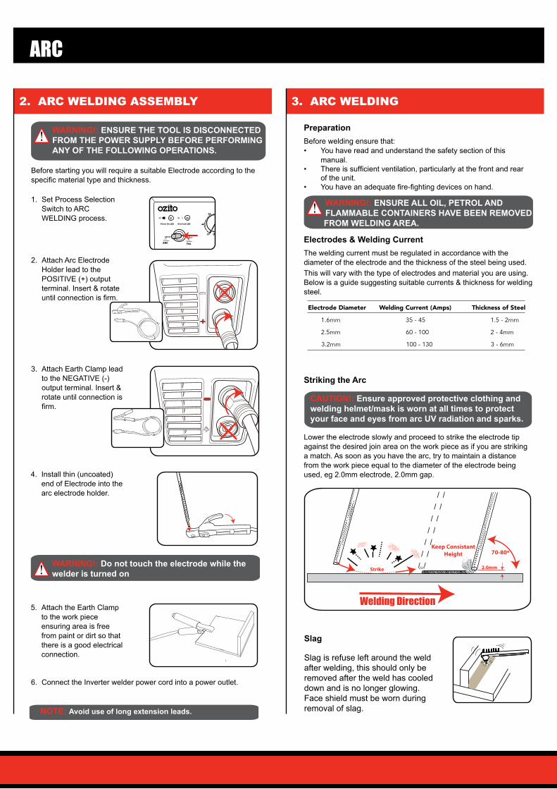
3. Attach Earth Clamp lead to the NEGATIVE (-) output terminal. Insert & rotate until connection is firm.
70-80º
Strike
Keep ConsistantHeight
2.0mm
Welding Direction
ARC
2. Attach Arc Electrode Holder lead to the POSITIVE (+) output terminal. Insert & rotate until connection is firm.
1. Set Process Selection Switch to ARC WELDING process.
PreparationBefore welding ensure that:• You have read and understand the safety section of this
manual.• There is sufficient ventilation, particularly at the front and rear
of the unit.• You have an adequate fire-fighting devices on hand.
Electrodes & Welding CurrentThe welding current must be regulated in accordance with the diameter of the electrode and the thickness of the steel being used.This will vary with the type of electrodes and material you are using. Below is a guide suggesting suitable currents & thickness for welding steel.
Electrode Diameter Welding Current (Amps) Thickness of Steel
1.6mm 35 - 45 1.5 - 2mm
2.5mm 60 - 100 2 - 4mm
3.2mm 100 - 130 3 - 6mm
6. Connect the Inverter welder power cord into a power outlet.
Striking the Arc
Lower the electrode slowly and proceed to strike the electrode tip against the desired join area on the work piece as if you are striking a match. As soon as you have the arc, try to maintain a distance from the work piece equal to the diameter of the electrode being used, eg 2.0mm electrode, 2.0mm gap.
WARNING!: ENSURE THE TOOL IS DISCONNECTED FROM THE POWER SUPPLY BEFORE PERFORMING ANY OF THE FOLLOWING OPERATIONS.
Before starting you will require a suitable Electrode according to the specific material type and thickness.
WARNING!: ENSURE ALL OIL, PETROL AND FLAMMABLE CONTAINERS HAVE BEEN REMOVED FROM WELDING AREA.
CAUTION!: Ensure approved protective clothing and welding helmet/mask is worn at all times to protect your face and eyes from arc UV radiation and sparks.
WARNING!: Do not touch the electrode while the welder is turned on
NOTE: Avoid use of long extension leads.
IWT-130
4. TIG WELDING ASSEMBLY
TIG
TIG Torch Assembly
Collet Body
1
Collet
Tungsten Electrode
2
Back Cap (Long)
5-6mm
4
Nozzle
3
TIG NozzlesCome in a wide variety of shapes and sizes depending on your torch and your welding application.Size #5, Ø 8mm #6, Ø10mm
Collet BodyCollet bodies screw into the TIG torch and accommodate various size tung-sten and their respective collet.Size 1.6mm I/D 2.4mm I/D
ColletsDirectly hold the tungsten in place when you tighten the back cap and create the electrical contact necessary for good current transfer.Size 1.6mm I/D 2.4mm I/D
5 6
Back CapsApply pressure to the back end of the collet to force it against the collet body. This pressure holds the tungsten in place and seals the torch head from the atmosphere. Back caps simply twist into the back of the torch to prevent the tungsten from slipping.
Basic TIG TorchThe components parts of a WP-17V TIG torch, collet bodies and collets are sized to match the electrode and should be fitted in matched sets.
66
Back Cap
Nozzle
Tungsten Electrode
Collet Body
Collet
Torch Body
GasWhen using the TIG function with the Inverter welder, you will require a gas regulator (flowmeter & tank gauge) connected to a bottle of inert gas. We recommend that you check for gas leakage prior to operation of your machine and you close the cylinder valve when the machine is not in use.
1
Inert GAS
Tungsten Electrode PreparationSharpening tungsten is very important for a nice fine arc strike.Grind lengthwise, not radial
PreparationBefore welding ensure that:• If you have not TIG welded before we recommend consulting
external information and practicing first.• You have read and understand the safety section of this
manual.• There is sufficient ventilation, particularly at the front and rear
of the unit.• You have an adequate fire-fighting devices on hand.
WARNING!: ENSURE ALL OIL, PETROL AND FLAMMABLE CONTAINERS HAVE BEEN REMOVED FROM WELDING AREA.
2-1/2 TimesElectrode Diameter
Grind Lengthwise Not Radial
60 grit or �neraluminium oxide
Flat spot 1/4 - 1/2 xElectrode Diameter
These additional accessories are available at your local gas supplier
Tungsten Electrode2% Cerium Tungsten (grey tipped).This tungsten requires less amperage to start so it is recommended for thinner metals, it can be used to weld every type of metalSize Ø1.6mm x 175mm Ø2.4mm x 175mm
TIG Torch Parts (included)
5. TIG WELDING
IWT-130U
Starting Arc
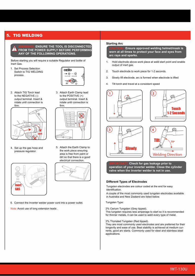
1. Hold electrode above work piece at weld start point and enable output of inert gas.
2. Touch electrode to work piece for 1-2 seconds.
3. Slowly lift electrode, arc is formed when electrode is lifted
4. Tilt torch and travel at a consistent speed
Touch1-2 Seconds
CAUTION!: Ensure approved welding helmet/mask is worn at all times to protect your face and eyes from arc rays and sparks.
1 2
Tilt
Welding Direction
75º
Slowly
3 4
IMPORTANT!: Check for gas leakage prior to operation of your inverter welder. Close the cylinder valve when the inverter welder is not in use.
2. Attach TIG Torch lead to the NEGATIVE (-) output terminal. Insert & rotate until connection is firm.
Lock
3. Attach Earth Clamp lead to the POSITIVE (+) output terminal. Insert & rotate until connection is firm.
5. Attach the Earth Clamp to the work piece ensuring area is free from paint or dirt so that there is a good electrical connection.
1. Set Process Selection Switch to TIG WELDING process.
4. Set up the gas hose and pressure regulator.
WARNING!: ENSURE THE TOOL IS DISCONNECTED FROM THE POWER SUPPLY BEFORE PERFORMING ANY OF THE FOLLOWING OPERATIONS.
Before starting you will require a suitable Regulator and bottle of Inert Gas.
1
Inert GAS
6. Connect the Inverter welder power cord into a power outlet.
Different Types of ElectrodesTungsten electrodes are colour coded at the end for easy identification.A couple of the most commonly used tungsten electrodes available in Australia and New Zealand are listed below.
Tungsten Type:
2% Cerium Tungsten (Grey tipped).This tungsten requires less amperage to start so it is recommended for thinner metals, it can be used to weld every type of metal.
2% Thoriated Tungsten (Red tipped).They are most commonly used electrodes and are preferred for their longevity and ease of use. Best stability is achieved at medium cur-rents, good arc starts. Commonly used for steel and stainless steel applications.
Note: Avoid use of long extension leads .
Thermal Overload
All Welders have a feature called a duty cycle.
Duty cycle on a welder refers to the time in which the welder operates during normal welding.
A welder can only weld for a certain continuous period of time before it requires to cool down.
If the internal components of the welder should become hot the welder could overheat. If the welder overheats the Thermal Overload Protection feature will automatically shut down the welder.
THIS CAN OCCUR IN HEAVY USE AND DOES NOT INDICATE A FAULT.
The Welder will cease to weld and the Thermal Overload LED light will turn on. This LED indication light is just to inform you that your welder is becoming too hot and requires to cool down to protect the internal components of the welder. Do Not turn your welder Off as the welder has an internal cooling fan and this will assist your welder to cool down quicker. Reducing the cooling time will enable you to get back to your welding job quicker.
Depending on how many Amps or how heavy the welding you are doing the cooling time may take up to 10 Minutes for your welder cool down so you can return to your welding job.
IF YOUR WELDER OVERHEATS AND THE THERMAL OVERLOAD PROTECTION ENGAGES DO NOT TURN YOUR WELDER OFF AS THE FAN WILL ASSIST IN REDUCING THE COOLING TIME.
Travel SpeedThe electrode should be moved along in the direction of the joint being welded at a speed that will give the size of run required. At the same time, the electrode is fed downwards to keep the correct arc length at all times. Excessive travel speeds lead to poor fusion and lack of penetration. While too slow a rate of travel will frequently lead to arc instability,slag inclusions and poor mechanical properties.
ElectricityThe electricity flows through the electrode cable to the attached electrode. The electricity will not leave the electrode unless it touches an earthed object.
Electricity always finds the fastest path to the earth. When the earth cable clamp is connected to the metal work piece a direct earth connection is created back to the welder. When the electrode makes contact with the earthed work piece an arc is created. The electricity flows through the electrode, the metal work piece and then through the earth cable straight back to the welder.
Earth ClampPrior to connecting the earth clamp it may be necessary to clean the surface of the work piece using the metal brush. Attach the earth clamp firmly to the work piece ensuring there is good metal to metal contact. Clamp it where it will not be in the way. This clamp provides an earth connection back to the welder. Always ensure the welder is disconnected from the power supply before attaching electrodes into the holder.
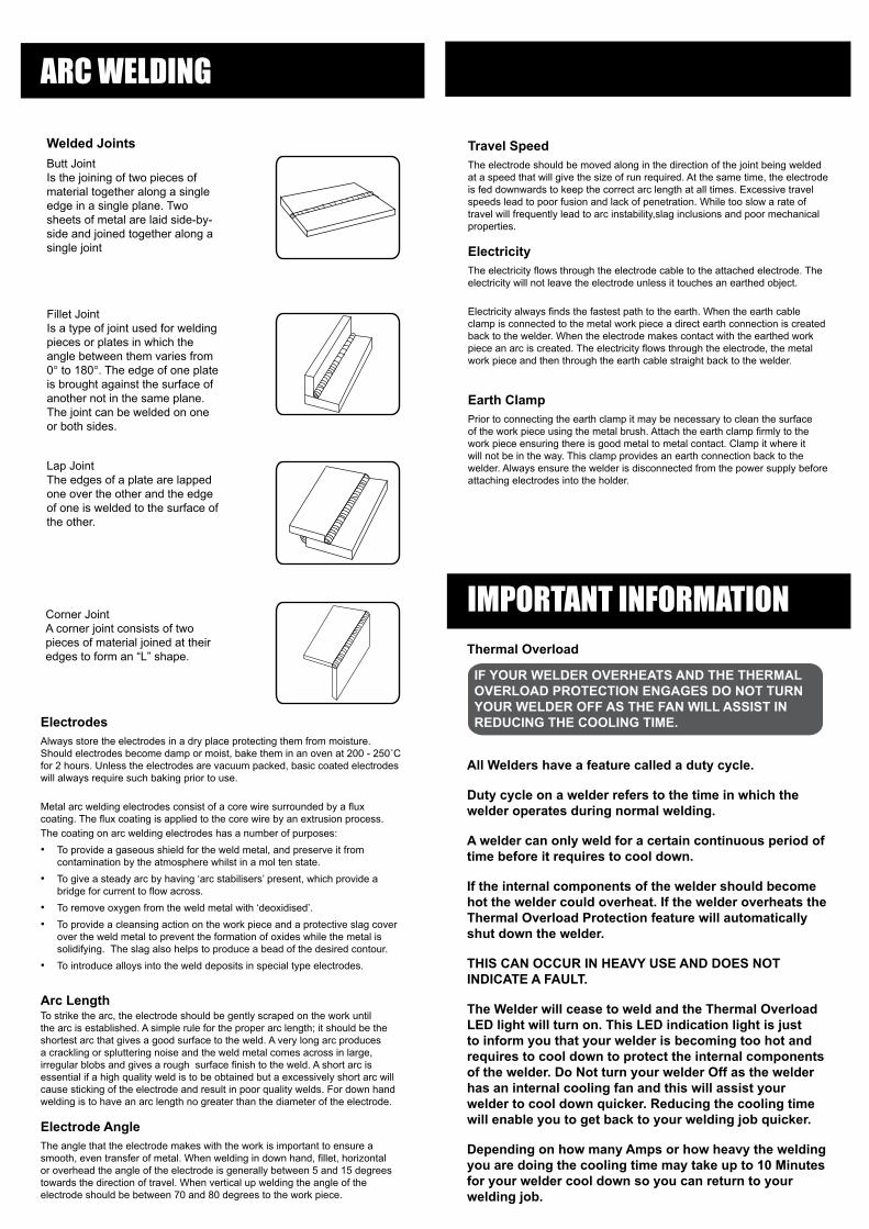
Welded JointsButt JointIs the joining of two pieces of material together along a single edge in a single plane. Two sheets of metal are laid side-by-side and joined together along a single joint
Fillet JointIs a type of joint used for welding pieces or plates in which the angle between them varies from 0° to 180°. The edge of one plate is brought against the surface of another not in the same plane. The joint can be welded on one or both sides.
Lap JointThe edges of a plate are lapped one over the other and the edge of one is welded to the surface of the other.
Corner JointA corner joint consists of two pieces of material joined at their edges to form an “L” shape.
ARC WELDING
ElectrodesAlways store the electrodes in a dry place protecting them from moisture. Should electrodes become damp or moist, bake them in an oven at 200 - 250˚C for 2 hours. Unless the electrodes are vacuum packed, basic coated electrodes will always require such baking prior to use.
Metal arc welding electrodes consist of a core wire surrounded by a flux coating. The flux coating is applied to the core wire by an extrusion process.The coating on arc welding electrodes has a number of purposes:• To provide a gaseous shield for the weld metal, and preserve it from
contamination by the atmosphere whilst in a mol ten state.• To give a steady arc by having ‘arc stabilisers’ present, which provide a
bridge for current to flow across.• To remove oxygen from the weld metal with ‘deoxidised’.• To provide a cleansing action on the work piece and a protective slag cover
over the weld metal to prevent the formation of oxides while the metal is solidifying. The slag also helps to produce a bead of the desired contour.
• To introduce alloys into the weld deposits in special type electrodes.
Arc LengthTo strike the arc, the electrode should be gently scraped on the work until the arc is established. A simple rule for the proper arc length; it should be the shortest arc that gives a good surface to the weld. A very long arc produces a crackling or spluttering noise and the weld metal comes across in large, irregular blobs and gives a rough surface finish to the weld. A short arc is essential if a high quality weld is to be obtained but a excessively short arc will cause sticking of the electrode and result in poor quality welds. For down hand welding is to have an arc length no greater than the diameter of the electrode.
Electrode AngleThe angle that the electrode makes with the work is important to ensure a smooth, even transfer of metal. When welding in down hand, fillet, horizontal or overhead the angle of the electrode is generally between 5 and 15 degrees towards the direction of travel. When vertical up welding the angle of the electrode should be between 70 and 80 degrees to the work piece.
IMPORTANT INFORMATION
DESCRIPTION OF SYMBOLS
SPARE PARTS
TROUBLESHOOTING
V Volts
~ Alternating current
U0 Non-load voltage
U2 On-load voltage
t W Load time
ø Diameter
X Load duration rate
U1 Rated AV input voltage (with tolerance ±10%)
A/V Electric current adjustment range, and the relevant on-load voltage
IP Protection class
Direct Current (DC)
Suitable for welding in an environment which has high risk of electric shock
MAG welding Gas Tungsten Arc Welding (GTAW)
Warning
Symbol of single-phase AV power and rated frequency
I1max Rated maximum input current I1eff Maximum effective input current
Vmax Max. wire feeding speed
A Amperes
Single-phase transformer- Rectifier
Do not operate in the rain
Read operator’s manual
1 F1F2
Hz Hertz
W Watts
t r Reset time
I 2 Current rating
PROBLEM CAUSE REMEDYGENERAL OPERATION
No Power Switch on rear is o� Turn on by moving switch to up position
Power supply Test supply with another product, avoid using extension leads.
Circuit breaker tripped Check the rating of the curcuit breaker on the supplyand other appliances conencted to the circuit.The welder is a high power device and it isrecommended that is be the only appliance on thecircuit to ensure it has enough power to operate.
Di�culty starting arc Incorrect settings, cable connection Check Arc/TIG switch is in correct postion. Check earth and eletrode cables are in correctterminals. Check cable conenctions to welder aresecure, rotate clockwise until �rm.
Earth clamp conenction not adequate Check earth clamp has good connection to materialbeing welded. Surface for clamp conenction needsto be bare metal, remove rust or paint.
Welding technique Hold electrode at correct angle, practice on scrapmaterial
Welder cuts out Thermal overload active The thermal overload light on the front panel willbe on and the welder will not operate until cooleddown and the light goes out. This is normal in heavywelding, allow the welder to cool down.
ARC WELDING
Poor welding Incorrect or wet welding electrodes Select electrode type to suit material, electrodes need to be dry.
Sticking weldingelectrode
Settings Increase current to recommended
Material Clean area being welded to bare metal
Electrode type and size Check the electrode type and size is appropriate forthe material being used.
Electrode damage Replace with new welding rod
Welding current setting too highExcessive welding electrode consumption
Reduce welding current
Electrode size to small for material Change to larger electrode
TIG WELDING
Poor welding Eletrode tip damaged Grind tip t point. Raplce with new TIG electrode
Gas supply Check the correct shield gas is being used. Checkgas supply connections and �ow settings.
Technique TIG welding requires skill and practice, seekassistance from experienced welder.
Spare parts can be ordered from the Special Orders Desk at your local Bunnings Warehouse or Homebase store. For further information, or any parts visit www.ozito-diy.co.uk or contact Ozito Customer Service: Great Britain: 0151 294 4488 Ireland: 1850 882711 E-mail: [email protected]
• Under no circumstances should the housing of the welder be opened.• Always protect your eyes and face with a welding mask.• Wear appropriate protective clothing such as a welding apron and sleeved gloves
etc.• Avoid exposing skin as UV rays are produced by the arc.• Screen off the work place to protect others working nearby from UV rays.• Welding materials with contaminated surfaces may generate toxic fumes. Ensure
the surface is clean before welding. Avoid operating on materials cleaned with chlorinated solvents or near such solvents.
• Do not weld metal equipment that holds/contains flammable materials, gases or liquid combustibles.
• Zinc-plated or galvanized material should not be welded as the fumes created are highly toxic.
• Do not use the welder in damp or wet conditions.• Do not use cables with worn insulation or loose connections.• Disconnect from the power supply before replacing electrodes.• Avoid direct contact with the welding circuit.• Do not use the welder to defrost piping.• Ensure the welder is placed on a level surface to prevent overturning.• Provide adequate ventilation or a means for removal of the welding fumes
produced (forced circulation using a blower or fan).
FumesToxic gases are given off during the ARC welding process, which may collect in the welding area if the ventilation is poor. Be alert at all times to the possibility of fume build-up. In small or confined areas use a fume extractor.
GlareThe electric arc generated by the ARC process gives direct heat and ultraviolet radiation. It is essential that the eyes of the operator and bystanders are protected from the glare during welding.
ALWAYS USE A FACESHIELD OR WELDING HELMET FITTED WITH THE CORRECT GLASS FILTER.
HeatIt is desirable that welding gloves are worn whilst welding. They will protect the hands from ultra-violet radiation and direct heat of the arc.
OVERALLS should also be worn. They should be of type designed to be buttoned at the wrists and the neck.
DressIn addition to face shield, welding gloves and overalls, other types of protective clothing should be worn when welding. Additional protective clothing such as a leather apron, sock protectors and a hat will all assist in reducing any injuries due to heat, sparks and slag produced during welding.
INVERTER WELDER SAFETY WARNINGS
WARNING! When using mains-powered tools, basic safety precautions, including the following, should always be followed to reduce risk of fire, electric shock, personal injury and material damage.
Read the whole manual carefully and make sure you know how to switch the tool off in an emergency, before operating the tool. Save these instructions and other documents supplied with this tool for future reference.Before you connect the equipment to mains supply make sure that the data on the rating plate are identical to the mains data.
If the supply cord is damaged, it must be replaced by an electrician or a power tool repairer in order to avoid a hazard.
Using an Extension LeadAlways use an approved extension lead suitable for the power input of this tool. Before use, inspect the extension lead for signs of damage, wear and ageing. Replace the extension lead if damaged or defective.When using an extension lead on a reel, always unwind the lead completely. Use of an extension lead not suitable for the power input of the tool or which is damaged or defective may result in a risk of fire and electric shock.
WARNING! Read all safety warnings and all instructions. Failure to follow the warnings and instructions may result in electric shock, fire and/or serious injury. Save all warnings and instructions for future reference. The term “power tool” in the
warnings refers to your mains-operated (corded) power tool or battery-operated (cordless) power tool.1. Keep work areas clean. Cluttered work areas and benches can cause accidents.
2. Consider work area environment. Do not expose your equipment to high humidity or rain. Do not use your equipment in damp or wet conditions. Keep the work area well lit. Do not use your tool where there is a risk of causing fire or explosion, e.g. in the presence of flammable liquids and gases.
3. Keep children away. Do not allow children, visitors or animals to come near the work area or to touch the equipment or accessories.
4. Dress appropriately. Wear the appropriate protective clothing. Wear a protective hair covering to keep long hair out of the way.
5. Guard against electric shock. Prevent body contact with earthed or grounded surfaces. Electrical safety can be further improved by using a high sensitivity (30 mA / 30 mS) residual current device (RCD).
6. Do not overreach. Keep proper footing and balance at all times.
7. Stay alert. Watch what you are doing. Use common sense. Do not operate the equipment when tired.
8. Secure work piece. If required, use clamps or a vice to hold the work piece.
9. Extension leads. Before use inspect the extension leads and replace if damaged. When using the equipment outdoors, only use extension leads intended for outdoor use and marked accordingly.
10. Use appropriate equipment. Only use the equipment as outlined within this instruction manual. Do not force the equipment to the job of heavier duty equipment. The equipment will do the job better and safer at the rate for which it was intended. Do not force the equipment.
WARNING! The use of any accessory or attachment, or performance of any operation with this equipment other than those recommended in this instruction manual may present a risk of personal injury.
11. Check for damaged parts. Before use carefully check the equipment and power lead for damage. Check for misalignment and seizure of moving parts, breakage of parts, damage to guards and switches and any other conditions that may affect its operation. Ensure the equipment will operate properly and perform its intended function. Do not use the equipment if any parts are damaged or defective. Do not use the equipment if the switch does not turn it on and off. Have any damaged or defective parts repaired or replaced by an electrician or a power tool repairer. Never attempt any repairs yourself
12. Unplug the equipment. Unplug the equipment when it is not in use, before changing any parts, accessories or attachments and before servicing.
13. Do not abuse the cord. Never carry the equipment by its cord or pull it to disconnect from the socket. Keep the cord away from heat, oil and sharp edges.
14. Store equipment. When not in use, equipment should be stored in a dry, locked up or high place,out of reach of children.
15. Maintain mains equipment with care. Keep the equipment clean and in good condition for better and safer performance. Follow the instructions for maintenance and changing accessories. Keep handles and switches dry, clean and free from oil and grease.
16. Have your tool repaired by an electrician or a power tool repairer. This power tool complies with relevant safety requirements. To avoid danger, electrical equipment must only be repaired by qualified technicians using original spare parts; otherwise this may result in considerable danger to the user.
17. Users. This equipment is not intended for use by young children or infirmed persons without supervision. Young children should be supervised to ensure that they do not play with this equipment.
18. Replacement of the supply cord. If the supply cord is damaged, it must be replaced by an electrician or a power tool repairer in order to avoid a hazard.
GENERAL POWER TOOL SAFETY WARNINGS
ELECTRICAL SAFETY
size 445 x 210 mm
Danger! - Read the operating instructions to re-duce the risk of inquiry
Caution! Danger from electric shock.
Do not store or use the equipment in wet con-ditions or in the rain. Use the equipment only indoors.
The reprinting or reproduction by any other me-ans, in whole or in part, of documentation and papers accompanying products is permitted only with the express consent of the iSC GmbH.
Subject to technical changes
The reprinting or reproduction by any other me-ans, in whole or in part, of documentation and papers accompanying products is permitted only with the express consent of the iSC GmbH.
Service informationWe have competent service partners in all countries named on the guarantee certificate whose contact details can also be found on the guarantee certificate. These partners will help you with all service re-quests such as repairs, spare and wearing part orders or the purchase of consumables.Please note that the following parts of this product are subject to normal or natural wear and that the following parts are therefore also required for use as consumables.
Category ExampleWear parts*Consumables* Welding ElectrodeMissing parts
* Not necessarily included in the scope of delivery!
In the effect of defects or faults, please register the problem on the internet at www.isc-gmbh.info. Plea-se ensure that you provide a precise description of the problem and answer the following questions in all cases:
• Did the equipment work at all or was it defective from the beginning?• Did you notice anything (symptom or defect) prior to the failure?• What malfunction does the equipment have in your opinion (main symptom)?
explains the following conformity according to EU directives and norms for the following product
Inverter Arc / Tig Welder IWT-130U (Ozito)
2014/29/EU 2005/32/EC_2009/125/EC
X 2014/35/EU 2006/28/EC
X 2014/30/EU 2014/32/EU 2014/53/EC 2014/68/EU 90/396/EC_2009/142/EC 89/686/EC_96/58/EC
X 2011/65/EU
2006/42/EC Annex IVNotifi ed Body:Notifi ed Body No.:Reg. No.:
2000/14/EC_2005/88/EC Annex V Annex VI Noise: measured LWA = dB (A); guaranteed LWA = dB (A)P = KW; L/Ø = cmNotifi ed Body:
2012/46/EUEmission No.:
Standard references: EN 60974-1; EN 60974-10;
Landau/Isar, den 20.10.2016
First CE: 16 Archive-File/Record: NAPR014332Art.-No.: 44.722.50 I.-No.: 11016 Documents registrar: R. GehardSubject to change without notice Wiesenweg 22, D-94405 Landau/Isar
ISC GmbH · Eschenstraße 6 · D-94405 Landau/Isar
Declaration of confirmity
Beiblatt_IWT_130U.indd 1 06.03.2017 10:00:30
size 445 x 210 mm
Items suppliedPlease check that the article is complete as specified in the scope of delivery. If parts are missing, please contact our service center or the sales outlet where you made your purchase at the latest within 5 working days after purchasing the product and upon presentation of a valid bill of purchase. Also, refer to the warranty table in the service information at the end of the operating instructions.• Open the packaging and take out the equip-
ment with care.• Remove the packaging material and any
• Check to see if all items are supplied.• Inspect the equipment and accessories for
transport damage.• If possible, please keep the packaging until
the end of the guarantee period.
Danger!The equipment and packaging material are not toys. Do not let children play with plastic bags, foils or small parts. There is a danger of swallowing or suffocating!
Proper useThe machine is to be used only for its prescribed purpose. Any other use is deemed to be a case of misuse. The user / operator and not the manufacturer will be liable for any damage or injuries of any kind caused as a result of this.
The equipment is to be used only for its prescri-bed purpose. Any other use is deemed to be a case of misuse. The user / operator and not the manufacturer will be liable for any damage or inju-ries of any kind caused as a result of this.
Please note that our equipment has not been de-signed for use in commercial, trade or industrial applications. Our warranty will be voided if the machine is used in commercial, trade or industrial businesses or for equivalent purposes.
Caution!Residual risksEven if you use this electric power tool in ac-cordance with instructions, certain residual risks cannot be rules out. The following ha-zards may arise in connection with the equip-ment’s construction and layout:1. Lung damage if no suitable protective dust
mask is used.2. Damage to hearing if no suitable ear protecti-
on is used.3. Health damage caused by hand-arm vibra-
tions if the equipment is used over a pro-longed period or is not properly guided and maintained.
Safety clothing1. While working, the welder must protect his en-
tire body from radiation and burns by wearing suitable clothing and a face guard. 2. Slip-on gloves made of a suitable material (leather) must be worn on both hands. They must be in perfect condition. 3. Suitable aprons must be worn to protect clo-
thing from sparks and burns. A safety suit and, if necessary, head protection must be worn if required by the type of work in question, e.g.
overhead welding.4. The protective clothing used as well as all
accessories must be in compliance with the “Personal safety equipment” EU Directive.
Protection from radiation and burns1. Provide information about the risk to eyes at
the working site in the form of a poster with the wording “Caution – do not look at the fla-mes”. Workplaces are to be screened off wherever possible so that personnel in the vicinity are protected. Unauthorized persons are to be kept away from the welding work.
2. The walls in the immediate vicinity of statio-nary workplaces should not have a light color or a sheen. Windows up to head height are to be protected against radiation passing th-rough them or reflecting off them, for example by coating them with a suitable paint.
For EU countries only
Never place any electric power tools in your household refuse.
To comply with European Directive 2012/19/EC concerning old electric and electronic equipment and its implementation in national laws, old electric power tools have to be separated from other waste and disposed of in an environment-friendly fashion, e.g. by taking to a recycling depot.
Recycling alternative to the return request:As an alternative to returning the equipment to the manufacturer, the owner of the electrical equipment must make sure that the equipment is properly disposed of if he no longer wants to keep the equipment. The old equipment can be returned to a suitable collection point that will dispose of the equipment in accordance with the national recycling and waste disposal regulations. This does not apply to any accessories or aids without electrical components supplied with the old equipment.
1~ 50 / 60 Hz
Highest welding time rated value in continuous mode tON (max) for highest welding current rated value at an ambient temperature of 20 °C, expres-sed in minutes and seconds.
Highest welding time rated value in intermittent mode ΣtON for highest welding current rated value at an ambient temperature of 20 °C over an un-interrupted time of 60 min, expressed in minutes and seconds.