7
Inverter Room Air Conditioner Installation Manual KSV26CRC, KSV26HRC, KSV35CRC, KSV35HRC, KSV53HRC, KSV62HRC, KSV70CRC, KSV70HRC, KSV80HRC Refrigerant R410A

Inverter Room Air Conditioner Installation Manual
KSV26CRC, KSV26HRC, KSV35CRC, KSV35HRC, KSV53HRC, KSV62HRC, KSV70CRC, KSV70HRC, KSV80HRC
Refrigerant R410A
caution
1 The unit must only be installed by a qualified refrigeration mechanic and electrical work carried out by a qualified electrician according to local or government regulations and in compliance with this manual.
2 Before installation, please contact a qualified air conditioner installer. If the unit is not installed by a qaulified air conditioner installer, the malfunction may not be solved due to faulty installation.
3 If the supply cord is damaged, it must be replaced by the manufacturer, its service agent or similarly qualified persons in order to avoid a hazard.
4 The appliance must be positioned so that the plug is accessible.
5 The temperature of refrigerant circuit will be high, please keep the interconnection cable away from the copper tube.
6 This appliance is not intended for use by persons (including children) with reduced physical, sensory or mental capabilities,or lack of experience and knowledge, unless they have been given supervision or instruction concerning use of the appliance by a person responsible for their safety.
Children should be supervised to ensure that they do not play with the appliance.
7 For appliances with type Y attachment,the instructions shall contain the substance of the following. If the supply cord is damaged,it must be replaced by the manufacturer, its service agent or similarly qualified persons in order to avoid a hazard.
warning
Before obtaining access to terminals, all supply circuits must be disconnected.
Please read this installation manual and the user manual before installation and carefully store in a handy place for later reference. Inside you will find many helpful hints on how to install and test the air conditioner properly.
Electrical work must be installed by a licensed electrician. Be sure to use the correct rating of the power plug and main circuit for the model to be installed.
Incorrect installation due to ignoring this instruction will cause harm or damage, and the seriousness is classified by the following indications.
Meanings of symbols used in this manual are shown below:
warning
This symbol indicates information concerning your personal safety
caution
This symbol indicates information on how to avoid damaging the appliance
tips and information
This symbol indicates tips and information about use of the appliance
environmental tip
This symbol indicates tips and information about economical and ecological use of the appliance
This symbol indicates never to do this
This symbol indicates always do this
Important safety instructions Notice for installation
2 Contents Kelvinator Air Conditioning
Congratulations and thank you for choosing our Inverter Speed Split room air conditioner. We are sure you will find your new air conditioner a pleasure to use. Before you use the air conditioner, we recommend that you read through the entire user manual, which provides the description of the air conditioner and its functions.
To avoid the risks that are always present when you use an electrical appliance, it is important that the air conditioner is installed correctly and that you read the safety instructions carefully to avoid misuse and hazards.
We recommend that you keep this instruction booklet for future reference and pass it on to any future owners.
After unpacking the air conditioner please check it is not damaged. If in doubt, do not use the air conditioner but contact your local Electrolux Customer Care Centre.
environmental tip
Information on disposal for users
• Most of the packing materials are recyclable. Please dispose of those materials through your local recycling depot or by placing them in appropriate collection containers.
• If you wish to discard this air conditioner, please contact your local authorities and ask for the correct method of disposal.
caution
• The air conditioner is not intended for use by young children or infirmed persons without supervision.
• Young children should be supervised to ensure that they do not play with the air conditioner.
• Contact an authorised installer for installation of this unit.
• Contact an authorised service technician for repair or maintenance of this unit.
• If the power cord is to be replaced, replacement work shall be performed by authorised personnel only.
• Installation work must be performed in accordance with the national wiring Standards by authorised personnel only.
Conditions of useThis appliance is intended to be useed in household and similar applications such as:
• Staff kitchen areas in shops, offices and other working environments
• Farm houses
• By clients in hotels, motels, and other residential type environments
• Bed and breakfast type environments
Contents ............................................................................ 2
Safety precautions ............................................................ 3
Notice for installation ....................................................... 3
Installation drawing .......................................................... 5
Installation of indoor unit ................................................. 6
Refrigerant pipe connection ............................................. 8
Installation of outdoor unit ............................................... 9
Check after installation and operation test .................... 10
Installation and Maintenance of HEPA Filter .................. 10
Warranty .......................................................................... 11
Congratulations Contents
Kelvinator Air Conditioning Important safety instructions/Notice for installation 3

Kelvinator Air Conditioning installation drawing 54 Notice for installation Kelvinator Air Conditioning
Safety Precautions for Electric Appliances
1 A dedicated power supply circuit should be used for products not supplied with a service cord and plug in accordance with local electrical safety regulations.
3 The unit must be reliably earthed and connected to the special earth device by the qualified electrician.
4 The circuit breaker must have the functions of magnetic tripping and heat tripping to prevent short circuit and overload.
5 The appliance shall be installed in accordance with national wiring regulations.
6 Including an circuit breaker with suitable capacity, please note the following table.
Model Circuit Breaker (Amps)
KSV26CRC 10
KSV26HRC 10
KSV35CRC 10
KSV35HRC 10
KSV53HRC 15
KSV62HRC 15
KSV70CRC 20
KSV70HRC 20
KSV80HRC 20
Note:• Make sure the live wire, neutral wire and earth wire in
the power socket are properly connected.
• Inadequate or incorrect electrical connections may cause electric shock or fire.
Earthing Requirements
1 Air conditioner is type I electric appliance. Please ensure the unit is reliably earthed.
2 The yellow-green wire in air conditioner is the earthing wire which can not be used for other purposes. Improper earthing may cause electric shock.
3 The earth resistance should accord to the national wiring regulation.
4 The user's power must have reliable earthing terminal. Do not connect the earthing wire with the following: 1. Water pipe 2. Gas pipe 3. Contamination pipe
Installation drawing
Installation Site Instructions
A proper installation site is vital for correct and efficient operation of the unit. Avoid the following sites where:
• strong heat sources, vapours, flammable gas or volatile liquids are emitted.
• high-frequency electro-magnetic waves are generated by radio equipment, welders or medical equipment.
• salt-laden air prevails (such as close to coastal areas).
• the air is contaminated with industrial vapours and oils.
• the air contains sulphurous gas such as in hot spring zones.
• corrosion or poor air quality exists.
Installation Site of Indoor Unit
1 The air inlet and outlet should be away from the obstructions. Ensure the air can be blown through the whole room.
2 Select a site where the condensing water can be easily drained out, and where it is easily connected for the outdoor unit.
3 Select a place where it is out of reach of children.
4 Select the place where the wall is strong enough to withstand the full weight and vibration of the unit.
5 Be sure to leave enough space to allow access for routine maintenance. The installation site should be 2m or more above the floor.
6 Select a place about 1m or more away from a TV set or any other electric appliance.
7 Select a place where the filter can be easily taken out.
8 Make sure that the indoor unit is installed in accordance with installation dimension instructions (refer to page 5).
9 Do not use the unit in the laundry or by swimming pool etc.
Installation Site of Outdoor Unit
1 Select a site where noise and outflow air emitted by unit will not annoy neighbors.
2 Select a site where there is sufficient ventilation.
3 Select a site where there is no obstruction blocking the inlet and outlet.
4 The site should be able to withstand the full weight and vibration of the unit.
5 Select a dry place, but do not expose the unit to direct sunlight or strong wind.
6 Make sure that the outdoor unit is installed in accordance with the installation instructions, and is convenient for maintenance and repair.
7 The height difference between indoor and outdoor units complies with the table on page 8.
8 Select a place where it is out of reach of children.
Space to the ceiling
Space to the wall
Space to the wall
Air outlet sideSpace to the floor
AboveAbove
15cm Above 15cm Above
300cm 200cm
15cmAbove
The dimensions of the minimum in between
If these dimensions are not adhered to the air conditioner willnot perform to specification, may not be able to be servicedand the warranty may be voided.the installation must allow for reasonable access
space necessary for properinstallation of the unit include the minimumpermissible distancesto adjacent parts.
●
Space to the wall
200cm A
bove
30cm Above
Space to the obstruction
Air outlet side
evob50
cm A
Space to the wall
Air inlet side
30cm Above
50cm Above

2 Insert the piping-hole sleeve into the hole to prevent the connection piping and wiring from being damaged when passing through the hole.
Ø Ø55/ 65
Indoor Outdoor
Wall pipe Seal pad
Installation of Drain Hose
1 Connect the drain hose to the outlet pipe of the indoor unit. Bind the joint with rubber belt.
drain hose
outlet pipe of indoor unitoutlet pipe of
indoor unitrubber belt
2 Put the drain hose into insulating tube.
insulating tube
drain hoseoutlet pipe of indoor unit
rubber belt
3 Wrap the insulating tube with wide rubber belt to prevent the shift of insulating tube. Slant the drain hose downward slightly for smooth drainage of condensing water.
outlet pipe of indoor unit
insulating tubeconnected
rubber belt
Note: The insulating tube should be connected reliably with the sleeve outside the outlet pipe. The drain hose should be slanted downward slightly, without distortion, bulge or fluctuation. Do not put the outlet in the water.
Installation of indoor unit
Installation of Mounting Plate
1 The mounting plate should be installed horizontally. As the water tray's outlet for the indoor unit is two-way type, during installation, the indoor unit should slightly slant to water tray's outlet for smooth drainage of condenser water.
2 Fix the mounting plate on the wall with screws.
3 Be sure that the mounting plate has been fixed firmly enough to withstand about 60kg. Meanwhile, the weight should be evenly shared by every screw.
Note: All dimensions are in mm.
2.6kW UNIT:
3.5kW UNIT:
Ø55 Ø55
34.5
34.5
316
6.2 kW, 7.0 kW and 8 kW UNITS:
5.2kW UNIT:
Drill Piping Hole
1 Slant the piping hole on the wall slightly downward to the outdoor side.
Piping hole Units
( 55) 2.6 kW, 3.5 kW and 5.3kW
( 65) 6.2 kW, 7.0 kW and 8 kW
6 Installation instructions Kelvinator Air Conditioning Kelvinator Air Conditioning Installation instructions 7
Installation of indoor and outdoor electric wires
1 Open the front panel.2 Remove the wiring cover connect and fix power
connection cord to the terminal board as shown in Fig 6.3 Make the power connection cord pass through the hole
at the back of indoor unit.4 Reinstall the cord anchorage and wiring cover.5 Reinstall the front panel.
For 2.6kW and 3.5kW units:
yellow-brownblackblue
2N(1) 3Wiring Cover
outdoor unit connection
green
For 5.3kW, 6.2kW, 7.0kW and 8kW units:
yellow-brownblackblue
2N(1) 3Wiring Cover
outdoor unit connection
green
Note: All wires between indoor and outdoor units must be connected by a qualified electric contractor.
• Electric wires must be connected correctly. Improper connection may cause malfunction.
• Tighten the terminal screws tightly.
• After tightening the screws, pull the wire slightly to confirm whether it's firm or not.
• Make sure that the electric connections are earthed properly to prevent electric shock.
• Make sure that all wiring connections are secure and the cover plates are reinstalled properly. Poor installation may cause fire or electric shock.
Installation of Indoor Unit
• The piping can be output from right, right rear, left or left rear.
1 When routing the piping and wiring from the left or right side of indoor unit, cut off the tailings from the chassis when necessary (As shown in Fig.1)
a. Cut off the tailings 1 when routing the wiring only; b. Cut off the tailings 1 and tailings 2 when routing both
the wiring and piping.
2 Take out the piping from body case, wrap the piping, power cords, drain hose with the tape and then make them pass through the piping hole. (As shown in Fig.2)
3 Hang the mounting slots of the indoor unit on the upper hooks of the mounting plate and check if it is firm enough. (As shown in Fig.3)
4 The installation site should be 2m or more above the floor.
Right
Right rear
Fig.2
Left rear
Left
Fig.1
Tailing 1Tailing 2
Finally wrap itwith tape
Gas side pipinginsulation
Water drainage pipe
Liquid sidePiping insulation
Gas side pipeExternal connection
electric wire
Liquid side piping
Fig.3
Mountingplate
Fixing hookMountingplate
Installation of Connection Pipe
Align the center of the piping flare with the related valve. Screw in the flare nut by hand and then tighten the nut with spanner and torque wrench by referring to the following:
Hex nut diameter Tightening torque (N·m)
6 15~20
9.52 30~40
12 45~55
16 60~65
19 70~75
For installations with connecting pipes greater than 5m, additional refrigerant is required at the following rates per extra metre of pipe.
2.6 kW & 3.5 kW Reverse cycle 20g/m 2.6 kW & 3.5kW Cooling only 15g/m 5.3 kW & 6.2 kW Reverse cycle 50g/m 7.0 kW Cooling only, 7.0 kW & 8.0 kW Reverse cycle 50g/m
bulge distortion
Flooded
Kelvinator Air Conditioning installation instructions 98 installation instructions Kelvinator Air Conditioning
Spanner Torquewrench
PipingTaper nutIndoor unit piping
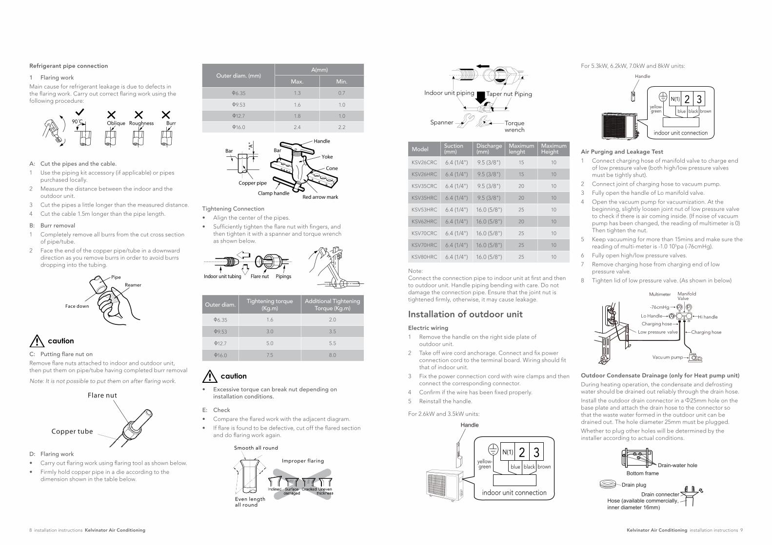
Model Suction (mm)
Discharge (mm)
Maximum lenght
Maximum Height
KSV26CRC 6.4 (1/4") 9.5 (3/8") 15 10
KSV26HRC 6.4 (1/4") 9.5 (3/8") 15 10
KSV35CRC 6.4 (1/4") 9.5 (3/8") 20 10
KSV35HRC 6.4 (1/4") 9.5 (3/8") 20 10
KSV53HRC 6.4 (1/4") 16.0 (5/8") 25 10
KSV62HRC 6.4 (1/4") 16.0 (5/8") 20 10
KSV70CRC 6.4 (1/4") 16.0 (5/8") 25 10
KSV70HRC 6.4 (1/4") 16.0 (5/8") 25 10
KSV80HRC 6.4 (1/4") 16.0 (5/8") 25 10
Note: Connect the connection pipe to indoor unit at first and then to outdoor unit. Handle piping bending with care. Do not damage the connection pipe. Ensure that the joint nut is tightened firmly, otherwise, it may cause leakage.
Installation of outdoor unitElectric wiring
1 Remove the handle on the right side plate of outdoor unit.
2 Take off wire cord anchorage. Connect and fix power connection cord to the terminal board. Wiring should fit that of indoor unit.
3 Fix the power connection cord with wire clamps and then connect the corresponding connector.
4 Confirm if the wire has been fixed properly.
5 Reinstall the handle.
For 2.6kW and 3.5kW units:
Handle
yellow-brownblackblue
2N(1) 3
indoor unit connection
green
For 5.3kW, 6.2kW, 7.0kW and 8kW units:
Handle
yellow-brownblackblue
2N(1) 3
indoor unit connection
green
Air Purging and Leakage Test
1 Connect charging hose of manifold valve to charge end of low pressure valve (both high/low pressure valves must be tightly shut).
2 Connect joint of charging hose to vacuum pump.
3 Fully open the handle of Lo manifold valve.
4 Open the vacuum pump for vacuumization. At the beginning, slightly loosen joint nut of low pressure valve to check if there is air coming inside. (If noise of vacuum pump has been changed, the reading of multimeter is 0) Then tighten the nut.
5 Keep vacuuming for more than 15mins and make sure the reading of multi-meter is -1.0 105pa (-76cmHg).
6 Fully open high/low pressure valves.
7 Remove charging hose from charging end of low pressure valve.
8 Tighten lid of low pressure valve. (As shown in below)
Multimeter
-76cmHg
Lo Handle
Charging hoseHi handle
Charging hoseLow pressure valve
ManifoldValve
Vacuum pump
Outdoor Condensate Drainage (only for Heat pump unit)
During heating operation, the condensate and defrosting water should be drained out reliably through the drain hose.
Install the outdoor drain connector in a 25mm hole on the base plate and attach the drain hose to the connector so that the waste water formed in the outdoor unit can be drained out. The hole diameter 25mm must be plugged.
Whether to plug other holes will be determined by the installer according to actual conditions.
Drain-water holeBottom frame
Drain plug
Hose (available commercially,inner diameter 16mm)
Drain connecter
Outer diam. (mm)A(mm)
Max. Min.
φ6.35 1.3 0.7
φ9.53 1.6 1.0
φ12.7 1.8 1.0
φ16.0 2.4 2.2
Bar
Copper pipe
Clamp handleRed arrow mark
Cone
Yoke
Handle
Bar"A"
Tightening Connection
• Align the center of the pipes.
• Sufficiently tighten the flare nut with fingers, and then tighten it with a spanner and torque wrench as shown below.
Indoor unit tubing Flare nut Pipings
Outer diam.Tightening torque
(Kg.m)Additional Tightening
Torque (Kg.m)
φ6.35 1.6 2.0
φ9.53 3.0 3.5
φ12.7 5.0 5.5
φ16.0 7.5 8.0
caution
• Excessive torque can break nut depending on installation conditions.
E: Check
• Compare the flared work with the adjacent diagram.
• If flare is found to be defective, cut off the flared section and do flaring work again.
Smooth all round
Improper flaring
Even lengthall round
Refrigerant pipe connection
1 Flaring work
Main cause for refrigerant leakage is due to defects in the flaring work. Carry out correct flaring work using the following procedure:
Oblique90 C Roughness Burr
A: Cut the pipes and the cable.
1 Use the piping kit accessory (if applicable) or pipes purchased locally.
2 Measure the distance between the indoor and the outdoor unit.
3 Cut the pipes a little longer than the measured distance.
4 Cut the cable 1.5m longer than the pipe length.
B: Burr removal
1 Completely remove all burrs from the cut cross section of pipe/tube.
2 Face the end of the copper pipe/tube in a downward direction as you remove burrs in order to avoid burrs dropping into the tubing.
Pipe
Reamer
Face down
caution
C: Putting flare nut on
Remove flare nuts attached to indoor and outdoor unit, then put them on pipe/tube having completed burr removal
Note: It is not possible to put them on after flaring work.
Flare nut
Copper tube
D: Flaring work
• Carry out flaring work using flaring tool as shown below.
• Firmly hold copper pipe in a die according to the dimension shown in the table below.
10 Kelvinator Air Conditioning installation instructions Kelvinator Air Conditioning warranty 11
This document sets out the terms and conditions of the product warranties for Electrolux Appliances. It is an important document. Please keep it with your proof of purchase documents in a safe place for future reference should you require service for your Appliance.1. Inthiswarranty (a) ‘acceptablequality’asreferredtoinclause10ofthiswarrantyhas
thesamemeaningreferredtointheACL; (b) ‘ACL’meansTradePracticesAmendment(AustralianConsumer
Law)Act(No.2)2010; (c) ‘Appliance’meansanyElectroluxproductpurchasedbyyou
accompaniedbythisdocument; (d) ‘ASC’meansElectrolux’authorisedservicedcentres; (e) ‘Electrolux’meansElectroluxHomeProductsPtyLtdof163
O’RiordanStreet,Mascot,NSW2020,ABN51004762341inrespectofAppliancespurchasedinAustraliaandElectrolux(NZ)Limitedof3-5NiallBurgessRoad,MountWellington,inrespectofAppliancespurchasedinNewZealand;
(f) ‘majorfailure’asreferredtoinclause10ofthiswarrantyhasthesamemeaningreferredtointheACLandincludesasituationwhenanAppliancecannotberepairedoritisuneconomicforElectrolux,atitsdiscretion,torepairanApplianceduringtheWarrantyPeriod;
(g) ‘WarrantyPeriod’means: (i) wheretheApplianceisusedforpersonal,domesticorhousehold
use(i.e.normalsinglefamilyuse)assetoutintheinstructionmanual,theApplianceiswarrantedagainstmanufacturingdefectsinAustraliafor24monthsandinNewZealandfortheperiodof24months,followingthedateoforiginalpurchaseoftheApplianceandafurther36months;inAustraliaifthereisevidenceprovidedtoElectroluxthattheappliancewasinstalledbyalicensedroomairconditionerinstaller;inNewZealandifthereisevidencethattheAppliancewasinstalledaccordingtotheElectroluxinstallationguidelineswhichcanbeinspectedontheKelvinatorwebsite;
(ii) wheretheApplianceisusedforcommercialpurposes(includingbeingusedtodirectlyassistabusinessorwheretheApplianceisusedinamulti-familycommunalorsharetypeenvironment),theAppliancewillthenbewarrantedagainstmanufacturingdefectsinAustraliafor3monthsandinNewZealandfor0months,followingthedateoforiginalpurchaseoftheAppliance.
(h) ‘you’meansthepurchaseroftheAppliancenothavingpurchasedtheApplianceforre-sale,and‘your’hasacorrespondingmeaning.
2. ThiswarrantyonlyappliestoAppliancespurchasedandusedinAustraliaorNewZealandandisinadditionto(anddoesnotexclude,restrict,ormodifyinanyway)anynon-excludablestatutorywarrantiesinAustraliaorNewZealand.
3. DuringtheWarrantyPeriodElectroluxoritsASCwill,atnoextrachargeifyourApplianceisreadilyaccessibleforservice,withoutspecialequipmentandsubjecttothesetermsandconditions,repairorreplaceanypartswhichitconsiderstobedefective.ElectroluxoritsASCmayuseremanufacturedpartstorepairyourAppliance.YouagreethatanyreplacedAppliancesorpartsbecomethepropertyofElectrolux.Thiswarrantydoesnotapplytolightglobes,batteries,filtersorsimilarperishableparts.
4. PartsandAppliancesnotsuppliedbyElectroluxarenotcoveredbythiswarranty.
5. Youwillbearthecostoftransportation,travelanddeliveryoftheAppliancetoandfromElectroluxoritsASC.Ifyouresideoutsideoftheservicearea,youwillbearthecostof:
(a) travelofanauthorisedrepresentative;
(b) transportationanddeliveryoftheAppliancetoandfromElectroluxoritsASC,
Inallinstances,unlesstheApplianceistransportedbyElectroluxoranElectroluxauthorisedrepresentative,theApplianceistransportedattheowner’scostandriskwhileintransittoandfromElectroluxoritsASC.
6. Proofofpurchaseisrequiredbeforeyoucanmakeaclaimunderthiswarranty.
7. Youmaynotmakeaclaimunderthiswarrantyunlessthedefectclaimedisduetofaultyordefectivepartsorworkmanship.Electroluxisnotliableinthefollowingsituations(whicharenotexhaustive):
(a) theApplianceisdamagedby:
(i) accident
(ii) misuseorabuse,includingfailuretoproperlymaintainorservice
(iii) normalwearandtear
(iv) powersurges,electricalstormdamageorincorrectpowersupply
(v) incompleteorimproperinstallation
(vi) incorrect,improperorinappropriateoperation
(vii)insectorvermininfestation
(viii)failuretocomplywithanyadditionalinstructionssuppliedwiththeAppliance;
(b) theApplianceismodifiedwithoutauthorityfromElectroluxinwriting;
(c) theAppliance’sserialnumberorwarrantysealhasbeenremovedordefaced;
(d) theAppliancewasservicedorrepairedbyanyoneotherthanElectrolux,anauthorisedrepairerorASC.
8. Thiswarranty,thecontracttowhichitrelatesandtherelationshipbetweenyouandElectroluxaregovernedbythelawapplicablewheretheAppliancewaspurchased.WheretheAppliancewaspurchasedinNewZealandforbusinesspurposestheConsumerGuaranteeActdoesnotapply.
9. Totheextentpermittedbylaw,Electroluxexcludesallwarrantiesandliabilities(otherthanascontainedinthisdocument)includingliabilityforanylossordamagewhetherdirectorindirectarisingfromyourpurchase,useornonuseoftheAppliance.
10.ForAppliancesandservicesprovidedbyElectroluxinAustralia,theAppliancescomewithaguaranteebyElectroluxthatcannotbeexcludedundertheAustralianConsumerLaw.Youareentitledtoareplacementorrefundforamajorfailureandforcompensationforanyotherreasonablyforeseeablelossordamage.YouarealsoentitledtohavetheAppliancerepairedorreplacediftheAppliancefailstobeofacceptablequalityandthefailuredoesnotamounttoamajorfailure.ThebenefitstoyougivenbythiswarrantyareinadditiontoyourotherrightsandremediesunderalawinrelationtotheAppliancesorservicestowhichthewarrantyrelates.
11.AtalltimesduringtheWarrantyPeriod,Electroluxshall,atitsdiscretion,determinewhetherrepair,replacementorrefundwillapplyifanAppliancehasavalidwarrantyclaimapplicabletoit.
12.ForAppliancesandservicesprovidedbyElectroluxinNewZealand,theAppliancescomewithaguaranteebyElectroluxpursuanttotheprovisionsoftheConsumerGuaranteesAct,theSaleofGoodsActandtheFairTradingAct.
13.Toenquireaboutclaimingunderthiswarranty,pleasefollowthesesteps: (a) carefullychecktheoperatinginstructions,usermanualandtheterms
ofthiswarranty; (b) havethemodelandserialnumberoftheApplianceavailable; (c) havetheproofofpurchase(eganinvoice)available; (d) telephonethenumbersshownbelow.14.Youacceptthatifyoumakeawarrantyclaim,ElectroluxanditsASC
mayexchangeinformationinrelationtoyoutoenableElectroluxtomeetitsobligationsunderthiswarranty.
WarrantyFORSALESINAUSTRALIAANDNEWZEALAND
APPLIANCE:KELVINATORSPLITSYSTEMAIRCONDITIONER
Important NoticeBeforecallingforservice,pleaseensurethatthestepslistedinpoint13abovehavebeenfollowed.
FOR SERVICE ortofindtheaddressofyournearest
stateservicecentreinAustraliaPLEASE CALL 13 13 49
Forthecostofalocalcall(Australiaonly)
SERVICE AUSTRALIA
ELECTROLUXHOMEPRODUCTSwww.electrolux.com.au
FOR SPARE PARTS ortofindtheaddressofyourneareststatesparepartscentreinAustralia
PLEASE CALL 13 13 50 Forthecostofalocalcall(Australiaonly)
FOR SERVICE ortofindtheaddressofyournearest
authorisedservicecentreinNewZealandFREE CALL 0800 10 66 10
(NewZealandonly)
SERVICE NEW ZEALAND
ELECTROLUXHOMEPRODUCTSwww.electrolux.co.nz
FOR SPARE PARTS ortofindtheaddressofyournearest
statesparepartscentreinNewZealandFREE CALL 0800 10 66 20
(NewZealandonly)
KSSAC_Warr_Apr11
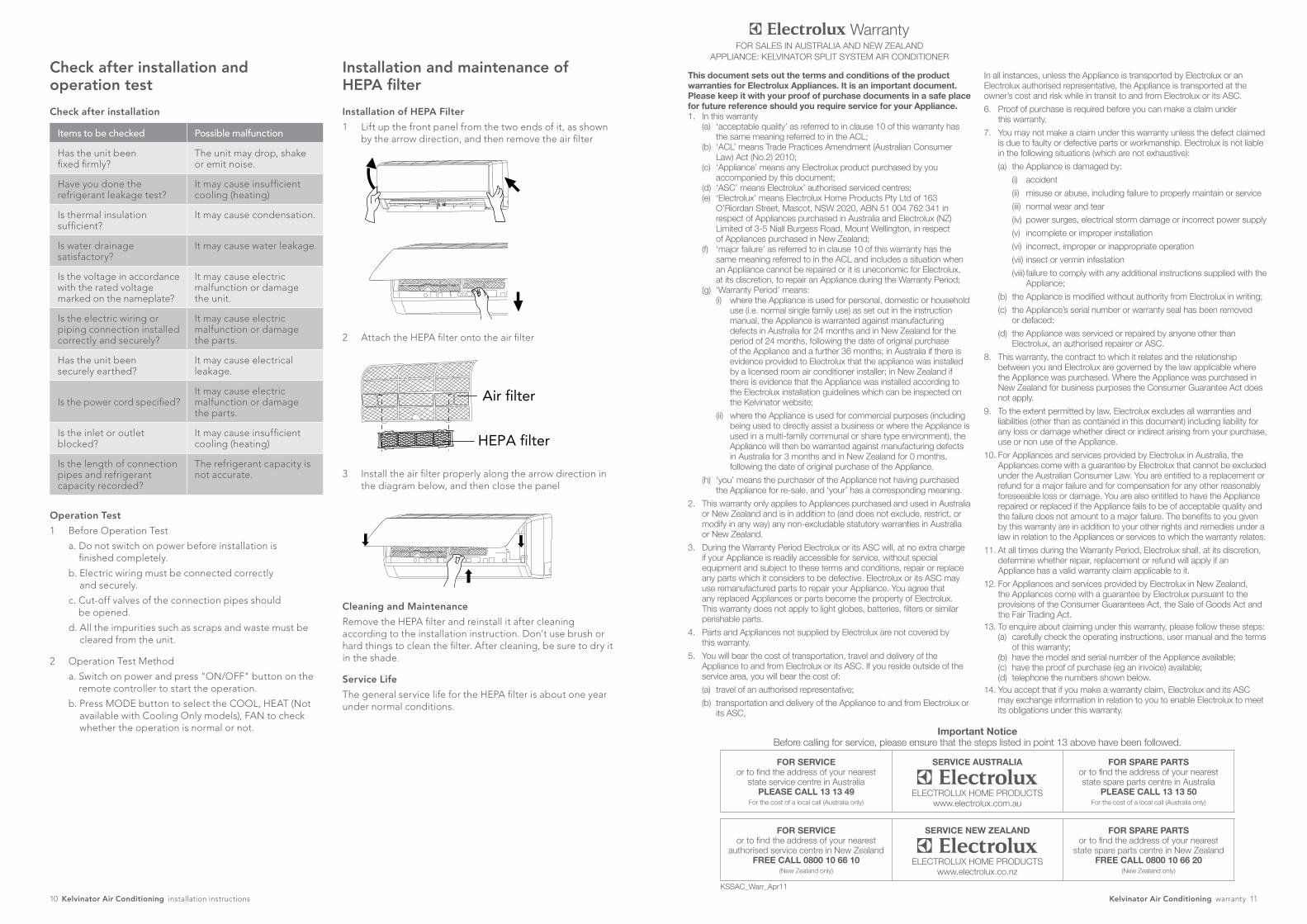
Installation and maintenance of HEPA filter
Check after installation and operation test
Check after installation
Items to be checked Possible malfunction
Has the unit been fixed firmly?
The unit may drop, shake or emit noise.
Have you done the refrigerant leakage test?
It may cause insufficient cooling (heating)
Is thermal insulation sufficient?
It may cause condensation.
Is water drainage satisfactory?
It may cause water leakage.
Is the voltage in accordance with the rated voltage marked on the nameplate?
It may cause electric malfunction or damage the unit.
Is the electric wiring or piping connection installed correctly and securely?
It may cause electric malfunction or damage the parts.
Has the unit been securely earthed?
It may cause electrical leakage.
Is the power cord specified?It may cause electric malfunction or damage the parts.
Is the inlet or outlet blocked?
It may cause insufficient cooling (heating)
Is the length of connection pipes and refrigerant capacity recorded?
The refrigerant capacity is not accurate.
Operation Test
1 Before Operation Test
a. Do not switch on power before installation is finished completely.
b. Electric wiring must be connected correctly and securely.
c. Cut-off valves of the connection pipes should be opened.
d. All the impurities such as scraps and waste must be cleared from the unit.
2 Operation Test Method
a. Switch on power and press "ON/OFF" button on the remote controller to start the operation.
b. Press MODE button to select the COOL, HEAT (Not available with Cooling Only models), FAN to check whether the operation is normal or not.
Installation of HEPA Filter
1 Lift up the front panel from the two ends of it, as shown by the arrow direction, and then remove the air filter
Air filter
HEPA filter
2 Attach the HEPA filter onto the air filter
Air filter
HEPA filter
3 Install the air filter properly along the arrow direction in the diagram below, and then close the panel
Air filter
HEPA filter
Cleaning and Maintenance
Remove the HEPA filter and reinstall it after cleaning according to the installation instruction. Don't use brush or hard things to clean the filter. After cleaning, be sure to dry it in the shade.
Service Life
The general service life for the HEPA filter is about one year under normal conditions.

© 2011 Electrolux Home Products Pty Ltd ABN 51 004 762 341
Print code: Airwave_IM_Jul11
If you’d like further information about Kelvinator appliances, please visit your retailer, phone or email our Customer Care team or visit our website.
telephone: 1300 363 640
fax: 1800 350 067
email: [email protected]
web: www.kelvinator.com.au
Kelvinator. We are part of the Electrolux family. Share more of our thinking at www.electrolux.com.au


![Midea HK( Midea Air ) aa Air o Air 03 . Aurora ] Split Type Inverter Air—Conditioner ( Cooling ) wi9 Split Type Inverter Air-Conditioner ( Heating ) 3} ENERGY LABEL (Inverter) E-COtäit](https://static.documents.pub/doc/80x56/5fdb3873aa22060bcb5bb018/midea-hk-midea-air-aa-air-o-air-03-aurora-split-type-inverter-airaconditioner.jpg)


