Investigation and improvement of ejector refrigeration system using computational fluid dynamics technique K. Pianthong a, * , W. Seehanam a , M. Behnia b , T. Sriveerakul a , S. Aphornratana c a Department of Mechanical Engineering, Ubon Ratchathani University, Ubon Ratchathani 34190, Thailand b Postgraduate Study, University of Sydney, Sydney, NSW, Australia c Department of Mechanical Engineering, Sirindhorn International Institute of Technology, Thammasart University, Pratumthani 12121, Thailand Received 4 August 2006; accepted 29 March 2007 Available online 29 May 2007 Abstract Ejector refrigeration systems are usually designed to utilize low grade energy for driving the cycle. They also have low maintenance cost because they operate without a compressor. Mainly, the ejector performance directly affects the refrigerating performance. There- fore, an investigation on the characteristics and an efficient design of the ejector are important to improve ejector refrigeration systems. In this study, the computational fluid dynamics (CFD) code, FLUENT, is employed to predict the flow phenomena and performance of CPM and CMA steam ejectors. The ejector refrigeration system, using water as the working fluid, is operated at 120–140 °C boiler temperature and 5–15 °C evapo- rator temperature. CFD can predict ejector performance very well and reveal the effect of operating conditions on an effective area that is directly related to its performance. Besides, it is found that the flow pattern does not depend much on the suction zone because the results of axisymmetric and 3D simulation are similar. This investigation aids the understanding of ejector characteristics and provides infor- mation for designing the ejector to suit the optimum condition. Ó 2007 Elsevier Ltd. All rights reserved. Keywords: Ejector; Ejector refrigeration; Computational fluid dynamics (CFD) 1. Introduction The ejector refrigeration system was firstly developed by Maurice Leblanc in 1910 [1]. This refrigeration system uti- lized low grade thermal energy or waste heat instead of using electricity. The main advantage of this system is its having fewer moving parts (no compressor). It is, therefore, very low in wear and significantly durable. It is also suit- able to operate using water as a refrigerant. However, it usually has a very low coefficient of performance (COP), and this becomes the critical issue and disadvantage of this system. Fig. 1 shows the operating cycle of the ejector refrigera- tion system. Comparing to the typical refrigeration cycle or vapor compression cycle, it can be seen that the ejector, the boiler (or steam generator) and the circulating pump are used to replace the compressor. The high pressure refriger- ant, boiled in the boiler, is the primary gas feeding to the primary nozzle. It then expands through the nozzle throat at supersonic speed and causes a low pressure area where it connects to the evaporator. Therefore, the refrigerant in the evaporator can boil and evaporate easily. The heat absorbed at the evaporator is the refrigerating capacity. The evaporated refrigerant is called the secondary gas. The primary and secondary gases are mixed and flow through the ejector to the condenser. The liquid refrigerant is pumped back to the boiler partly, and some portion is fed through the expansion valve and evaporator to com- plete the cycle. It can be seen that the refrigeration perfor- mance of the system depends much on the performance of the ejector to induce the refrigerant flow rate through the evaporator. 0196-8904/$ - see front matter Ó 2007 Elsevier Ltd. All rights reserved. doi:10.1016/j.enconman.2007.03.021 * Corresponding author. Tel.: +66 45 353 382; fax: +66 45 353 333. E-mail address: [email protected](K. Pianthong). www.elsevier.com/locate/enconman Energy Conversion and Management 48 (2007) 2556–2564
Transcript
www.elsevier.com/locate/enconman
Energy Conversion and Management 48 (2007) 2556–2564
Investigation and improvement of ejector refrigeration systemusing computational fluid dynamics technique
K. Pianthong a,*, W. Seehanam a, M. Behnia b, T. Sriveerakul a, S. Aphornratana c
a Department of Mechanical Engineering, Ubon Ratchathani University, Ubon Ratchathani 34190, Thailandb Postgraduate Study, University of Sydney, Sydney, NSW, Australia
c Department of Mechanical Engineering, Sirindhorn International Institute of Technology, Thammasart University, Pratumthani 12121, Thailand
Received 4 August 2006; accepted 29 March 2007Available online 29 May 2007
Abstract
Ejector refrigeration systems are usually designed to utilize low grade energy for driving the cycle. They also have low maintenancecost because they operate without a compressor. Mainly, the ejector performance directly affects the refrigerating performance. There-fore, an investigation on the characteristics and an efficient design of the ejector are important to improve ejector refrigeration systems.In this study, the computational fluid dynamics (CFD) code, FLUENT, is employed to predict the flow phenomena and performance ofCPM and CMA steam ejectors.
The ejector refrigeration system, using water as the working fluid, is operated at 120–140 �C boiler temperature and 5–15 �C evapo-rator temperature. CFD can predict ejector performance very well and reveal the effect of operating conditions on an effective area that isdirectly related to its performance. Besides, it is found that the flow pattern does not depend much on the suction zone because the resultsof axisymmetric and 3D simulation are similar. This investigation aids the understanding of ejector characteristics and provides infor-mation for designing the ejector to suit the optimum condition.� 2007 Elsevier Ltd. All rights reserved.
The ejector refrigeration system was firstly developed byMaurice Leblanc in 1910 [1]. This refrigeration system uti-lized low grade thermal energy or waste heat instead ofusing electricity. The main advantage of this system is itshaving fewer moving parts (no compressor). It is, therefore,very low in wear and significantly durable. It is also suit-able to operate using water as a refrigerant. However, itusually has a very low coefficient of performance (COP),and this becomes the critical issue and disadvantage of thissystem.
Fig. 1 shows the operating cycle of the ejector refrigera-tion system. Comparing to the typical refrigeration cycle or
0196-8904/$ - see front matter � 2007 Elsevier Ltd. All rights reserved.
vapor compression cycle, it can be seen that the ejector, theboiler (or steam generator) and the circulating pump areused to replace the compressor. The high pressure refriger-ant, boiled in the boiler, is the primary gas feeding to theprimary nozzle. It then expands through the nozzle throatat supersonic speed and causes a low pressure area where itconnects to the evaporator. Therefore, the refrigerant inthe evaporator can boil and evaporate easily. The heatabsorbed at the evaporator is the refrigerating capacity.The evaporated refrigerant is called the secondary gas.The primary and secondary gases are mixed and flowthrough the ejector to the condenser. The liquid refrigerantis pumped back to the boiler partly, and some portion isfed through the expansion valve and evaporator to com-plete the cycle. It can be seen that the refrigeration perfor-mance of the system depends much on the performance ofthe ejector to induce the refrigerant flow rate through theevaporator.
Fig. 1. Operating cycle of ejector refrigeration cycle.
K. Pianthong et al. / Energy Conversion and Management 48 (2007) 2556–2564 2557
Usually, the two parameters indicating ejector perfor-mance are entrainment ratio (Em) and critical back pres-sure (CBP). Em is defined as shown in Eq. (1), whileCBP is the final pressure (condensing pressure) with theejector working at its maximum capability.
Entrainment ratio Em¼mass flow rate of secondary flow
mass flow rate of primary flow
ð1ÞTypically, ejectors are categorized in two types based on
the mixing concept at the primary nozzle exit. The first oneis the constant mixing area (CMA) ejector in which the exitof the primary nozzle is placed at the constant area throat.The second type is the constant pressure mixing (CPM)ejector in which the exit of the primary nozzle is placedat the converging area throat. The setup of both theCMA and CPM ejector are shown in Fig. 2. These twoejectors are suitable to use in different situations. TheCMA is capable of drawing more mass flow rate than theCPM, but the CPM is more flexible or suitable to operatein wider condensing pressure ranges.
In the past, the performances of the two ejectors havealready been researched in ejector refrigeration systems.However, not much information on the ejector characteris-tics was reported in detail when there were many parame-ters involved. Also, they were mainly experimental worksand were quite limited in the testing conditions. Therefore,this study aims to use the computational fluid dynamics(CFD) technique to simulate ejector performance in vari-ous conditions and to suggest the best possible solutions.
Fig. 2. Two typical ejector types: (a) constant pressure mixing ejector and(b) constant mixing area ejector.
Recently, a new concept of ejector design has been pro-posed by Eames [2]. It is called the constant rate of momen-tum change (CRMC) concept for which the ejector isexpected to combine the benefits of CMA and CPM ejec-tors and perform better. In the CRMC concept, a new pro-file of the diffuser or diverging section of the ejector isproposed. It is claimed that the entrainment ratio of theCRMC is slightly higher than that of the CPM, and theCBP is significantly improved. Garris et al. [3] try toenhance the efficiency of the ejector by reducing the speedof the primary gas by allowing it to expand through a selfrotating skew. By rotating the primary gas, the loss duringmixing will be lower. From the Garris idea, Chang andChen [4,5] have developed the petal nozzle and found thatthe Em and CBP of the ejector can be higher. However,Garris’s and Chang’s ejectors are quite complicated instructure compared to a typical ejector and are difficultto use in practice.
For many years, researchers have tried to investigateand describe the phenomena of ejector flow in order todevelop a high performance ejector. Keenan and his team[6,7] were the first group who proposed an ejector theory.It is a one dimensional ejector flow theory and widely usedto predict the properties of the fluid along the ejector axisbased on mixing and gas dynamics theory. This theorywas widely used, however, it could not describe the con-stant capacity effect when the exit pressure is decreased.Later, Munday and Bagster [8] successfully adopted theeffective area concept (as shown in Fig. 3) within the calcu-lation and showed good agreement with experiment. Theystudied this phenomenon and described that the primaryand secondary fluids do not mix until their flow velocitiesreach the sonic condition. It is similar to the flow passingthrough the throat of the convergent–divergent nozzleand choking (of secondary fluid) phenomenon occurs.The flow area where the secondary fluid chokes is called‘‘effective area’’ (as shown in Fig. 3).
Then, the ejector performance in the refrigeration sys-tem can be predicted. However, these concepts are notproved yet due to the limitation of experimentation andmeasurements, and there are still many factors involvingthe ejector performance.
Riffat et al. [9] simulated the flow behavior inside theejector of the refrigeration system using methanol as refrig-erant. He found that the CFD results agreed well with theexperimental results and can be used to predict other vari-ous conditions. Rusly et al. [10,11] investigated the flow
Fig. 3. Effective area occurring in the ejector throat.
2558 K. Pianthong et al. / Energy Conversion and Management 48 (2007) 2556–2564
characteristics of the ejector in a refrigeration system byusing the real gas model in the commercial code, FLU-ENT, and found good agreement as well.
In this paper, the CFD code, FLUENT, is employed toinvestigate the flow phenomena and performance of twotypical ejectors used in refrigeration systems, which arethe CMA and CPM ejector. The results are validated withexperiments and simulation in other various conditions.Thus, the most preferable conditions can be applied in sys-tem design.
2. CFD for flow simulations
2.1. Computational modeling for ejector flow
The ejector model used in this study is shown in Fig. 4.The model is composed of the primary nozzle and the ejec-tor. The primary nozzle accelerates the high speed gas andinduces the secondary flow through the ejector. The ejectorconsists of four parts, which are the secondary inlet, mixingchamber, throat, and diffuser. The primary nozzle is usuallyplaced at the entrance of the secondary inlet. However, theposition of the primary nozzle, called nozzle exit position orNXP, can be varied and affects the ejector performance.
Fig. 4. Ejector geometry (2D) u
Fig. 5. 3D ejector geometry us
The CFD code used in this study is FLUENT (version6.0.12). The model ejector is the one used in Chunnan-ond’s study [12]. The ejector geometry is set as axisym-metric. About 48000 nodes of quadrilateral mesh areused. The dense meshes are preset at the mixing zonealong the exit of the primary nozzle as shown in Fig. 4.This is to cope with the high gradient properties aroundthat area. The solving method is couple implicit. The real-izable k � e turbulence model is selected while the stan-dard near wall function is used in the near walltreatment. Boundary conditions are the pressure inletand outlet. The energy equation is included, while thefluid property is defined as an ideal gas. In addition, athree dimensional model (3D) is also investigated. Thisis to determine the effect of the third dimension, com-pared to the axisymmetric model (ASXM), on the ejectorperformance at the area around the suction pipe. Thehexahedral cell, 5,000,000 nodes, is used in the 3D modelas shown in Fig. 5.
2.2. Comparison of ASXM and 3D results
The 3D model of CPM ejector was simulated in order tocheck whether the suction pipe has any effects on the
sed in the CFD simulation.
ed in the CFD simulation.
Fig. 6. Comparison of wall static pressure along the ejector from 2D (AXSM) and 3D model.
Fig. 7. Validation of the CFD and experimental results (a) at various boiler temperatures and (b) at various evaporator temperatures.
K. Pianthong et al. / Energy Conversion and Management 48 (2007) 2556–2564 2559
entrainment ratio of the ejector. The results of ASXM and3D simulations are compared in Fig. 6. It shows very closevalues of static pressure along the ejector axis. Other prop-erties are also very close. In both models, the pressuresgradually increase and slightly fluctuate along the mixingchamber and ejector throat and then smoothly increase inthe diffuser. From this comparison, it maybe summarizedthat the ASXM is good enough to give accurate results,and the 3D model is not necessary for further investigation.
2.3. Validation of CFD simulations
Validation of the CFD results using experimental workhas been done in this study and also confirmed with thework of Chunnanond [13]. The effect of the condensingpressure at various boiler temperatures and evaporatortemperatures has been investigated. For example, theresults are shown in Fig. 7. The results of Em and CBPfrom CFD are slightly different from the results from theexperiments, around 5%.
3. Results
It is well known that the ejector is the key equipment inthe ejector refrigeration cycle because it determines themass flow rate of the refrigerant in the evaporator (i.e.refrigerating capacity) and also the condensing pressure
(i.e. heat rejecting capacity). This study, therefore, investi-gates the effects of various operating conditions and ejectorgeometries on the Em and CPB of the CPM and CMAejectors.
3.1. Effect of operating conditions
The change of operating condition certainly affects Emand CBP. Detailed investigations are performed by CFDhere. Fig. 8, shows that a higher boiler temperature givesa higher CBP but lower Em in both CPM and CMA ejec-tors. The evaporator temperature also affects the ejectorperformance by increasing Em and CBP when the evapo-rator temperature increases in both ejector types. How-ever, at the same operating conditions, the CMA usuallygives a higher mass flow rate or Em, but yields a lowerCBP.
3.2. Effect of ejector geometry
3.2.1. Effect of NXP on ejector performance
In this investigation, the ejector performance is deter-mined when the nozzle exit position (NXP) is varied at var-ious operating conditions. The results are shown in Fig. 9.It is found that a higher entrainment ratio can be obtainedwhen the NXP is moved further from the ejector inlet(negative direction). By doing this, the effective area in
Fig. 8. Effect of operating conditions on ejector performance (a) at various boiler temperature and (b) at various evaporating temperature.
Fig. 9. Effect of NXP on ejector performances (a) at various boiler temperature and (b) at various evaporating temperature.
2560 K. Pianthong et al. / Energy Conversion and Management 48 (2007) 2556–2564
the ejector throat is getting bigger, and therefore, Em ishigher. However, there is only one optimum position. Ifthe NXP is moved too far, the momentum of the primarygas will be lower and cause a lower Em. Therefore, theCFD simulation is very useful in this case to decide themost suitable NXP in the actual system in particular oper-ating conditions.
Fig. 10. Effect of throat length on ejector perform
3.2.2. Effect of throat length on ejector performance
In this study, the throat length (TL) is the variable, whileNXP = 0 and the mixing chamber is 125 mm (see Fig. 4).Both the CPM and CMA ejectors are investigated at vari-ous operating conditions as before.
Fig. 10 shows the effect of the throat length on the ejec-tor performance at various operating conditions. It reveals
ances (a) CMA ejector and (b) CPM ejector.
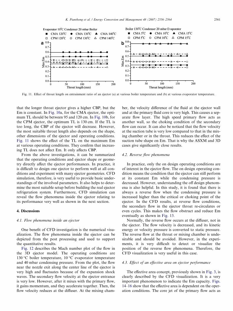
Fig. 11. Effect of throat length on entrainment ratio of an ejector (a) at various boiler temperature and (b) at various evaporator temperature.
K. Pianthong et al. / Energy Conversion and Management 48 (2007) 2556–2564 2561
that the longer throat ejector gives a higher CBP, but theEm is constant. In Fig. 10a, for the CMA ejector, the opti-mum TL should be between 95 and 120 cm. In Fig. 10b, forthe CPM ejector, the optimum TL is 130 cm. If the TL istoo long, the CBP of the ejector will decrease. However,the most suitable throat length also depends on the shape,other dimensions of the ejector and operating conditions.Fig. 11 shows the effect of the TL on the maximum Emat various operating conditions. They confirm that increas-ing TL does not affect Em. It only affects CBP.
From the above investigations, it can be summarizedthat the operating conditions and ejector shape or geome-try directly affect the ejector performances. In practice, itis difficult to design one ejector to perform well at all con-ditions and experiment with many ejector geometries. CFDsimulation, therefore, is very useful to provide basic under-standings of the involved parameters. It also helps to deter-mine the most suitable setup before building the real ejectorrefrigeration system. Furthermore, CFD simulation canreveal the flow phenomena inside the ejector relating toits performance very well as shown in the next section.
4. Discussions
4.1. Flow phenomena inside an ejector
One benefit of CFD investigation is the numerical visu-alization. The flow phenomena inside the ejector can bedepicted from the post processing and used to supportthe quantitative results.
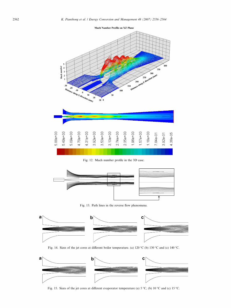
Fig. 12 describes the Mach number plot of the flow inthe 3D ejector model. The operating conditions are130 �C boiler temperature, 10 �C evaporator temperatureand 40 mbar condensing pressure. From the plot, the flownear the nozzle exit along the center line of the ejector isvery high and fluctuates because of the expansion shockwaves. The secondary flow velocity at the ejector entranceis very low. However, after it mixes with the primary flow,it gains momentum, and they accelerate together. Then, theflow velocity reduces at the diffuser. At the mixing cham-
ber, the velocity difference of the fluid at the ejector walland at the primary fluid core is very high. This causes a sep-arate flow layer. The high speed primary flow acts asanother wall, so the choking condition of the secondaryflow can occur. It can also be noticed that the flow velocityat the suction tube is very low compared to that in the mix-ing chamber or in the throat. This reduces the effect of thesuction tube shape on Em. That is why the ASXM and 3Dcases give significantly close results.
4.2. Reverse flow phenomena
In practice, only the on design operating conditions areof interest in the ejector flow. The on design operating con-dition means the condition that the ejector can still performat its constant Em while the condensing pressure isdecreased. However, understanding the off design phenom-ena is also helpful. In this study, it is found that there isalways a reverse flow when the condensing pressure isincreased higher than the critical or choking point of theejector. In the CFD results, at reverse flow conditions,the secondary flow in the ejector throat re-circulates oreven cycles. This makes the flow obstruct and reduce Emeventually as shown in Fig. 13.
Normally, the reverse flow occurs at the diffuser, not inthe ejector. The flow velocity is decreased, and its kineticenergy or velocity pressure is converted to static pressure.The reverse flow at the throat or mixing chamber is unde-sirable and should be avoided. However, in the experi-ments, it is very difficult to detect or visualize theposition of the reverse flow phenomena. Therefore, theCFD visualization is very useful in this case.
4.3. Effect of an effective area on ejector performance
The effective area concept, previously shown in Fig. 3, isclearly described by the CFD visualization. It is a veryimportant phenomenon to indicate the Em capacity. Figs.14–16 show that the effective area is dependent on the oper-ation conditions. The core jet of the primary flow acts as
Fig. 12. Mach number profile in the 3D case.
Fig. 13. Path lines in the reverse flow phenomena.
Fig. 14. Sizes of the jet cores at different boiler temperature. (a) 120 �C (b) 130 �C and (c) 140 �C.
Fig. 15. Sizes of the jet cores at different evaporator temperature (a) 5 �C, (b) 10 �C and (c) 15 �C.
2562 K. Pianthong et al. / Energy Conversion and Management 48 (2007) 2556–2564
Fig. 16. Sizes of the jet cores at different condenser pressure (a) 20 mbar, (b) 25 mbar, (c) 30 mbar, (d) 35 mbar (CBP), (e) 38 mbar and (f) 40 mbar.
K. Pianthong et al. / Energy Conversion and Management 48 (2007) 2556–2564 2563
another wall. Therefore, the case that has the bigger effec-tive area has the better Em (120 �C boiler temperature inthis case). Fig. 15 shows the effective area when the evapo-rating temperature is varied. At higher evaporating temper-ature, the effective area is bigger, thereby giving the higherEm. These results correspond well with the performanceinvestigation in the previous sections.
The ejector back pressure or condensing pressure alsoaffects the ejector performance. If the shape of the jet coreis examined carefully, while the condensing pressure islower than the critical back pressure (CBP), the jet core size(i.e. effective area) does not change. Therefore, Em is con-stant. However, when the condensing pressure is higherthan the critical back pressure (CBP), the jet core is smaller(i.e. bigger effective area), but Em does not increase. Thiscan be summarized that the effective area concept is provedonly at the on design operating conditions.
4.4. Effect of mixing process on build up of static pressure
In the mixing process of the primary and secondaryfluid, the momentum of the two fluids is exchangedthrough the flow layer. The efficiency of the mixing candirectly affect the regained pressure (build up of static pres-sure) of the ejector. The two factors involved are the size ofthe mixing chamber and the mixing period. If the size of themixing chamber is small, the momentum transfer is quitecomplete. Therefore, the ejector can give high static pres-sure such as the CPM ejector. In addition, when the mixingchamber is small, the effective area will be small as well,and the ejector will give low Em. For the mixing period,if there is a long mixing period, the momentum transfer willbe quite complete. That is why the reasonably long throatejector can give higher static pressure or work well athigher CBP.
5. Concluding remarks
This study employs CFD techniques to investigate theflow characteristics of the ejector used in an ejector refrig-
eration system. The CFD results have been validated withexperimental results. The axisymmetric and 3D cases havebeen compared in order to determine if the shape of thesuction tube has affected the ejector performance. Theresults show very similar solutions because the flow veloc-ity at the suction is very low and is not significant to theoverall flow behavior. The effects of various operation con-ditions on the ejector performance have been investigated.Ejector shapes or geometries are also varied and the ejectorperformance simulated. The CFD visualization becomes agreat benefit in the study because it can reveal the phenom-ena inside the ejector in detail. In summary, the overallview points on ejector performance related to its flow phe-nomena can be understood and become very useful tools todesign an appropriate ejector for each particular case.
Acknowledgement
This research is financially supported by the Thai Re-search Fund (TRF), Contract No. MRG4680175.
References
[1] Chunnanond K, Aphornratana S. Ejectors: application in refrigera-tion technology. Renew Sust Eng Rev 2004;8:129–55.
[2] Eames IW. A new prescription for design of supersonic jet pumps:constant rate of momentum change method. Appl Therm Eng2002;22:121–31.
[3] Hong WJ, Alhussan K, Zhang H, Garris Jr CA. A novel thermallydriven rotor – vane/pressure-exchange ejector refrigeration systemwith environmental benefits and energy efficiency. Energy 2004;29:2331–45.
[4] Chang YJ, Chen YM. Enhancement of a steam-jet refrigerator usinga novel application of the petal nozzle. Exp Therm Fluid Sci2000;22:203–11.
[5] Chang YJ, Chen YM. Enhancement of a steam-jet refrigerator usinga novel application of the petal nozzle. J Chin Inst Eng 2000;23:677–86.
[6] Keenan JH, Neumann EP. A simple air ejector. J Appl Mech-TASME 1942;64:75–81.
[7] Keenan JH, Neumann EP, Lustwerk F. An investigation of ejectordesign by analysis and experiment. J Appl Mech-T ASME 1950;72:299–309.
2564 K. Pianthong et al. / Energy Conversion and Management 48 (2007) 2556–2564
[8] Munday JT, Bagster DF. A new theory applied to steam jetrefrigeration. Ind Eng Chem Proc DD 1997;16(4):442–9.
[9] Riffat SB, Omer SA. CFD modelling and experimental investigationof an ejector refrigeration system using methanol as the working fluid.Int J Eng Res 2001;25:115–28.
[10] Rusly E, Aye L, Charters WWS, Ooi A, Pianthong K. Ejector CFDmodelling with real gas model. In: Proceedings of the 16th annualconferenceofmechanical engineeringnetworkThailand;2002.p.150–5.
[11] Rusly E, Aye L, Charters WWS, Ooi A. CFD analysis of ejector in acombined ejector cooling system. Int J Refrig 2005;28:1092–101.
[12] Chunnanond K, Aphornratana S. An experimental investigation of astream ejector refrigerator: the analysis of the pressure profile alongthe ejector. Appl Therm Eng 2004;24:311–22.
[13] Chunnanond K. A study of steam ejector refrigeration cycle,parameters affecting performance of ejector. Ph.D. Thesis of Sirind-horn International Institute of Technology University 1994.


![CFD Simulation of Ejector in Steam Jet Refrigeration...to faultlessly. Anticipate those execution of the steam jet refrigeration framework, impacts of the essential nozzle’s [4].](https://static.documents.pub/doc/80x56/5e897add438ad91bf87773a4/cfd-simulation-of-ejector-in-steam-jet-refrigeration-to-faultlessly-anticipate.jpg)

