INVESTIGATION OF ELECTRON BEAM WELDING OF AHSS BY PHYSICAL AND NUMERICAL SIMULATION Raghawendra P. S. Sisodia 1 , Marcell Gáspár 2 PhD student 1 , Assistant Professor 2 1,2 Institute of Materials Science and Technology, University of Miskolc, Miskolc 3515, Hungary ABSTRACT The electron beam welding (EBW) sets new standards as it facilitates very high quality and effective welding of high strength structural steels. The technology ensures high-quality critical welded joints in thicker structural metals. It has a high energy density in comparison to the conventional arc welding processes (e.g. GMAW). As a result of less overall energy input and higher velocity, the effect of welding on the base material in the heat-affected zone (HAZ) and the distortion is much smaller compared to conventional arc welding processes. The low heat input result in a small HAZ and a reduced extension of critical HAZ areas which can be favourable in high strength steels when the mechanical properties can drastically decrease in the HAZ. In comparison with experimental studies, a numerical modelling study can provide detailed information concerning the welding process and parameters, and the number of costly experiments can be reduced. Finite element modelling (FEM) of EBW enables the estimation of temperature field, time temperature curve, weld pool geometry and welding distortion etc. The determination of the temperature field can be very useful in terms of the further investigations since the t8/5 cooling time can be less than 2 s during EBW. In this paper, by the application of Sysweld software, the time-temperature curve was determined and the physical simulation of the critical HAZ subzones were performed using a GLEEBLE 3500 physical simulator in order to analyse the properties of HAZ during extremely short cooling time. Keywords: Electron Beam Welding (EBW), Finite element modelling (FEM), HAZ characteristics, Gleeble 3500 thermophysical simulator, t8/5 cooling time, 3D conical heat source INTRODUCTION In keeping the view of modern world where advancement in technology is prime requirement to drive economic growth and sustainable development objective within the world. Several steel manufacturers have increased their interest in ultra- high strength quenched and tempered steels [1][2]. The development of high strength weldable steels has diversified the field of application, range of design alternatives subjected to more severe operation conditions than previous time. Nowadays high strength steels are gaining more popularity in welded structures, even in ship building and machinery components. Advanced High Strength Steel (AHSS) are more complex, particularly through their microstructures, which are usually multiphase for MultiScience - XXXIII. microCAD International Multidisciplinary Scientific Conference University of Miskolc, 23-24 May, 2019, ISBN 978-963-358-177-3 DOI: 10.26649/musci.2019.051
Transcript
INVESTIGATION OF ELECTRON BEAM WELDING OF AHSS BY
PHYSICAL AND NUMERICAL SIMULATION
Raghawendra P. S. Sisodia1, Marcell Gáspár2
PhD student1, Assistant Professor2 1,2Institute of Materials Science and Technology, University of Miskolc, Miskolc
3515, Hungary
ABSTRACT
The electron beam welding (EBW) sets new standards as it facilitates very high
quality and effective welding of high strength structural steels. The technology
ensures high-quality critical welded joints in thicker structural metals. It has a high
energy density in comparison to the conventional arc welding processes (e.g.
GMAW). As a result of less overall energy input and higher velocity, the effect of
welding on the base material in the heat-affected zone (HAZ) and the distortion is
much smaller compared to conventional arc welding processes. The low heat input
result in a small HAZ and a reduced extension of critical HAZ areas which can be
favourable in high strength steels when the mechanical properties can drastically
decrease in the HAZ. In comparison with experimental studies, a numerical modelling
study can provide detailed information concerning the welding process and
parameters, and the number of costly experiments can be reduced. Finite element
modelling (FEM) of EBW enables the estimation of temperature field, time
temperature curve, weld pool geometry and welding distortion etc. The determination
of the temperature field can be very useful in terms of the further investigations since
the t8/5 cooling time can be less than 2 s during EBW. In this paper, by the application
of Sysweld software, the time-temperature curve was determined and the physical
simulation of the critical HAZ subzones were performed using a GLEEBLE 3500
physical simulator in order to analyse the properties of HAZ during extremely short
cooling time.
Keywords: Electron Beam Welding (EBW), Finite element modelling (FEM), HAZ
characteristics, Gleeble 3500 thermophysical simulator, t8/5 cooling time, 3D conical
heat source
INTRODUCTION
In keeping the view of modern world where advancement in technology is
prime requirement to drive economic growth and sustainable development objective
within the world. Several steel manufacturers have increased their interest in ultra-
high strength quenched and tempered steels [1][2]. The development of high strength
weldable steels has diversified the field of application, range of design alternatives
subjected to more severe operation conditions than previous time. Nowadays high
strength steels are gaining more popularity in welded structures, even in ship building
and machinery components. Advanced High Strength Steel (AHSS) are more
complex, particularly through their microstructures, which are usually multiphase for
MultiScience - XXXIII. microCAD International Multidisciplinary Scientific ConferenceUniversity of Miskolc, 23-24 May, 2019, ISBN 978-963-358-177-3
DOI: 10.26649/musci.2019.051
an improved combination of strength and ductility. This balance is carefully used to
meet performance requirements while maintaining excellent formability [3]. This
high strength can be achieved with minimum yield strength up to 1300 MPa, AHSS
often has other advantageous mechanical properties, such as high strain-hardening
capacity. They provide high strength to weight ratios, very good acceptable
weldability especially where overmatched welds are used, improved toughness and
sufficient deformation capacity. Financial benefits can also be realized through
reduced transportation and lifting costs (reduced weight), material savings
(smaller/lighter sections) and reduced weld volumes (thinner plates). Easier and
simple structural components and construction techniques are also possible,
especially for large structures, and establishment costs may also be reduced due to
lower dead weight [4]. High strength steels are available for structural applications,
as in bridges, buildings, offshore applications etc., all around the world. A very high
carbon equivalent value indicates poor weldability and these steels are not suitable
for structural applications, where welding is very important to assure structural safety
[5]. The future of AHSS for automotive applications is bright. The weldability of high
strength steels consists of more challenges compared to mild steels: hardening of the
heat-affected zone (HAZ) and higher cold cracking sensitivity; reduction of strength
and/or toughness of HAZ; selection of filler material (mismatch) [6]. Therefore, new
welding conceptions and special welding technology should be developed for these
steels. For the advanced high strength steels innovative welding technologies can be
needed (e.g. laser beam, electron beam, laser-GMAW hybrid welding technology)
which may have benefits for the joint properties and the production costs. Generally,
these welding processes result narrow HAZ, which is often the most problematic part
of the welded joint in AHSS. By these technologies the extension of the critical areas
(softened or hardened zones) can be minimized [7]. Regarding the economic
advantages the high productivity and the less filler material costs should be
emphasised. Due to the narrow and deep penetrated weld structure (keyhole
technique) lower amount of filler material is needed. It can be also beneficial to the
mechanical properties of the whole welded joints since in AHSS the weld can be
similarly critical as the HAZ.
Electron Beam Welding (EBW) is a highly efficient, flexible [8] and precise welding
method increasingly used within the manufacturing chain and of growing importance
in different industrial environments such as the automobile, aeronautical, aerospace
(3A), construction, and power generation sectors [9]. It is also observed from two
referred research paper that numerically simulated cooling time can be extremely
short: t8/5 = 0.49 s [10] & t8/5 = 2 s [11] for EBW.
With the development of various new high strength steel and their difficulty in
weldabilities arises the other promising welding technology that can be applied for
high and ultra- high strength steels is the electron beam welding process [12]. So far,
the studies of electron beam welding on high strength quenched and tempered steel
and thermo mechanically controlled steel with different yield strength have not been
carried out extensively, therefore their suitability should be investigated before. Since
they are very expensive technologies, therefore the application of numerical and
physical simulation is suggested before the real welding experiments and the
production.
EXPERIMENTAL METHODOLOGY
The first phase of experimental steps involves the numerical simulation that
containing steps like creation of geometry of the required model, selecting type,
order, method of element for further mesh creation, providing boundary conditions,
weld path, reference line, clamping conditions etc. Then analysis is performed which
can be either thermo-metallurgical or mechanical analysis together or separately
depending upon requirement and finally simulated data were generated with detailed
analysis. The important parameters considered for numerical simulation for S960QL
material were presented in Table 1, which seems quite satisfactory with real
experiment data with EBW for 10 mm thickness plate and velocity 10 mm/s [13].
The needed material properties of the steel S355J2 are integrated in the FE software
SYSWELD and used for the calculations because it is similarly low alloyed as
S960QL, therefore there is no a big difference in the thermo-physical properties. The
efficiency is a very important parameter and it is considered η=1 for EBW analysis.
The efficiency influenced the amount of the heat source power. [14]
Table 1
Simulation parameters
Welding
process
Heat input
(J/mm)
Velocity
(mm/s)
Simulated
time (t8/5)
(s)
Cooling
medium
EBW 600 14 2 Free air
cooling
Second phase of experimental steps is the physical simulation and the simulation
parameters were determined iteratively by running calculations with more parameters
in order to find the optimal EBW parameters [15]. Unfortunately, proper toughness
evaluation of HAZ is far more difficult than for a homogeneous material. Because of
the very local heat input, a weld offers various zones with different microstructures
and therefore different properties (metallurgical notch) [16] and the third phase is the
materials testing. A Gleeble 3500 thermomechanical simulator was used to simulate
the welding thermal cycles of the heat-affected zone of S960QL steel. Square base
specimen (10 mm x10 mm x 70 mm) were prepared and subjected to thermal cycle
[15].
The high cost of the material and the process does not allow for trial and error
approach in optimizing the process and, therefore, modelling and simulations
approaches are being used increasingly with continuous improvement brought on
better heat source modelling and more reliable predictions on the influence of process
parameters on the distribution of HAZ, residual stresses and distortions. Finite
element (FE) simulations have been the most common numerical method used to
simulate the welding process, thermal and mechanical analyses [17]. Modern finite
element codes not only allow for calculation of deformations and stresses due to the
welding process but also take into account the change of microstructure due to
different heating and cooling rates [18]. For an advanced high strength steel structure
or sample such effects shall be investigate and quantify using advanced material
modelling and FE simulation [19]. The electron beam welding (EBW) numerical
model was created using SYSWELD software. Weld plate is modelled and simulated
on 3D finite element method (FEM) using the SYSWELD software and this is
specifically used for thermal analysis. It basically involves three important steps in
welding simulation, these are modelling, analysis and post processing. The sample
geometry, materials and heat sources fitting belong to the first steps i.e. modelling in
weld simulation sequence.
Meshing
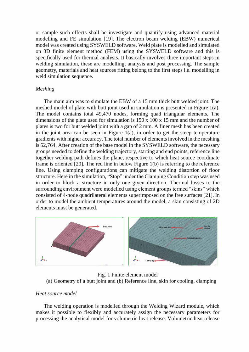
The main aim was to simulate the EBW of a 15 mm thick butt welded joint. The
meshed model of plate with butt joint used in simulation is presented in Figure 1(a).
The model contains total 49,470 nodes, forming quad triangular elements. The
dimensions of the plate used for simulation is 150 x 100 x 15 mm and the number of
plates is two for butt welded joint with a gap of 2 mm. A finer mesh has been created
in the joint area can be seen in Figure 1(a), in order to get the steep temperature
gradients with higher accuracy. The total number of elements involved in the meshing
is 52,764. After creation of the base model in the SYSWELD software, the necessary
groups needed to define the welding trajectory, starting and end points, reference line
together welding path defines the plane, respective to which heat source coordinate
frame is oriented [20]. The red line in below Figure 1(b) is referring to the reference
line. Using clamping configurations can mitigate the welding distortion of floor
structure. Here in the simulation, “Stop” under the Clamping Condition step was used
in order to block a structure in only one given direction. Thermal losses to the
surrounding environment were modelled using element groups termed “skins” which
consisted of 4-node quadrilateral elements superimposed on the free surfaces [21]. In
order to model the ambient temperatures around the model, a skin consisting of 2D
elements must be generated.
Fig. 1 Finite element model
(a) Geometry of a butt joint and (b) Reference line, skin for cooling, clamping
Heat source model
The welding operation is modelled through the Welding Wizard module, which
makes it possible to flexibly and accurately assign the necessary parameters for
processing the analytical model for volumetric heat release. Volumetric heat release
takes place as a result of the introduction of heat in accordance with several thermal
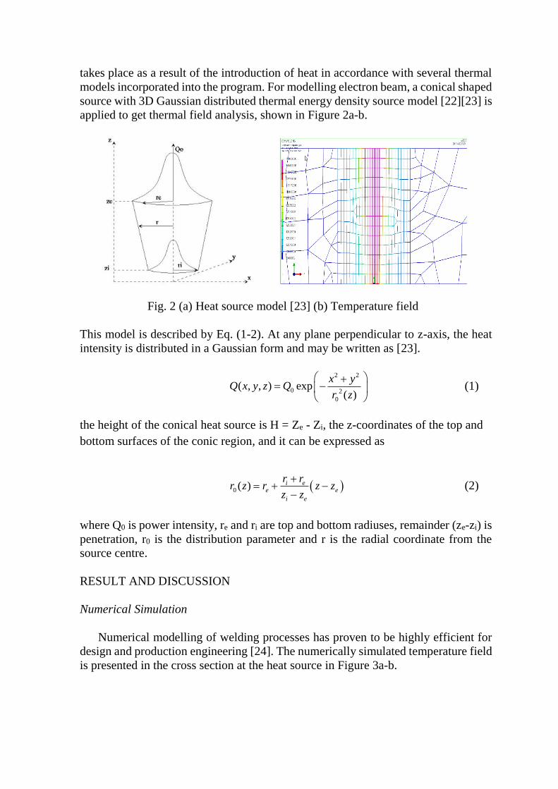
models incorporated into the program. For modelling electron beam, a conical shaped
source with 3D Gaussian distributed thermal energy density source model [22][23] is
applied to get thermal field analysis, shown in Figure 2a-b.
Fig. 2 (a) Heat source model [23] (b) Temperature field
This model is described by Eq. (1-2). At any plane perpendicular to z-axis, the heat
intensity is distributed in a Gaussian form and may be written as [23].
2 2
0 2
0
( , , ) exp( )
x yQ x y z Q
r z
+= −
(1)
the height of the conical heat source is H = Ze - Zi, the z-coordinates of the top and
bottom surfaces of the conic region, and it can be expressed as
( )0 ( ) i ee e
i e
r rr z r z z
z z
+= + −
− (2)
where Q0 is power intensity, re and ri are top and bottom radiuses, remainder (ze-zi) is
penetration, r0 is the distribution parameter and r is the radial coordinate from the
source centre.
RESULT AND DISCUSSION
Numerical Simulation
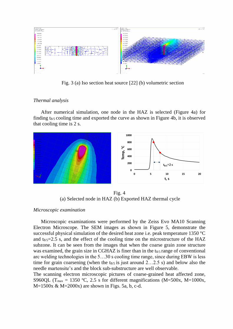
Numerical modelling of welding processes has proven to be highly efficient for
design and production engineering [24]. The numerically simulated temperature field
is presented in the cross section at the heat source in Figure 3a-b.