Investigation of Magnetic Wedge Effects in Large-Scale BDFMs S. Abdi † , E. Abdi § , A. Oraee † , R. A. McMahon † † Electrical Engineering Division, Cambridge University, Cambridge CB3 0FA, UK § Wind Technologies Ltd, St Johns Innovation Park, Cambridge CB4 0WS, UK Keywords: BDFM (Brushless Doubly Fed Machines), FEM (Finite Element Method), Magnetic Wedges. Abstract This paper studies the effects of magnetic wedges on the equivalent circuit parameters of the Brushless Doubly-Fed Machine (BDFM). Magnetic wedges are used in slot openings of large electrical machines to reduce magnetizing currents, but the study of their effects on the BDFM performance is not straightforward due to the complex magnetic fields in the BDFM. Equivalent circuit and FE models have been developed for a 250 kW BDFM taking into account the effects of wedges and verified experimentally. 1 Introduction Doubly-fed Induction Generators (DFIG) are the most widely used generators in wind turbines and it has been shown in [1] that brush gear and slip-rings are the major failure cause in DFIGs. The BDFM is an alternative to the well-established DFIG for use in wind turbines as it retains the benefit of utilizing a converter rated at only a fraction (~30-50%) of the generator rating depending on the speed range and reactive power requirement, but it offers higher reliability and hence lower cost of ownership than the DFIG due to absence of brush gear and slip-rings. In addition, the BDFM is intrinsically a medium-speed machine, enabling the use of a simplified one or two-stage gearbox, hence reducing the cost and weight of the overall drive train and giving further reliability improvement. Therefore, BDFM is very attractive for use as a wind turbine generator, especially for offshore wind farms. The BDFM has two sets of balanced three-phase stator windings wound in the stator slots, spanning the whole circumference of the machine, and are configured such that they produce two fields of different pole numbers (2P 1 and 2P 2 ). The pole numbers are selected in a way to avoid direct transformer coupling between the stator windings and the coupling between the windings is through the rotor [7]. The rotor has a short-circuited configuration, which couples the fields of both windings by induction. The nested loop winding is the most widely used although other configurations are possible [7]. To date, several groups have reported experimental BDFMs [2,4,5] and there have been attempts to manufacture large BDFMs, for example in Brazil with a 75 kW machine [2], China with the design of a 200 kW machine [4] and most recently, the 250 kW reported by the authors [5]. The latter was built in a frame size D400 as a stepping-stone towards a megawatt-scale BDFM wind turbine and it involved construction and winding techniques appropriate to large machines. The equivalent circuit is a simple method of representing the steady-state performance of the machine. Since the meaning of the parameters has a clear physical interpretation, the equivalent circuit can be very helpful for the machine understanding, design and optimization. The equivalent circuit is used to calculate the voltage, current, torque, efficiency, power factor and other steady-state measures of the machine. The equivalent circuit parameters can be calculated from the machine geometry using the method described in [6], or from experimental measurements as described in [7]. Magnetic wedges [8] are used as a slot wedge in open slot design machines. They can reduce core losses, and hence, motor temperature rise as well as effective air gap length resulting in lower magnetizing current and, hence, improve power factor [3]. Typically the magnetic wedge material comprises 75% iron powder, 7% glass mat, and 18% epoxy resin [3]. However, in spite of all advantages offered by magnetic wedges in improving the performance of electrical machines, they are more brittle and susceptible to failure than non-magnetic ones due to high percentage of iron powder in the magnetic wedge [3]. Magnetic wedges have been used in the stator slot openings of the D400 BDFM to reduce magnetizing currents, but it also has a significant effect on the rotor inductance. Since the rotor inductance has a key role in various performance measures of the BDFM, such as reactive power management, low-voltage ride-through performance and converter rating requirement, the assessment of effects of magnetic wedges in the BDFM is important. Such effects have not been previously investigated since large scale BDFMs have only recently being constructed. This paper investigates the effects of magnetic wedges on the performance of the BDFM by analysing their impact on the equivalent circuit parameters. Such effects have been widely investigated for large induction motors, but these studies are not readily applicable to the BDFM since it has a more complex design. The modelling and experimental results presented in this paper are for the 250 kW D400 BDFM.
Transcript
Investigation of Magnetic Wedge Effects in Large-Scale BDFMs S. Abdi †, E. Abdi §, A. Oraee †, R. A. McMahon †
† Electrical Engineering Division, Cambridge University, Cambridge CB3 0FA, UK § Wind Technologies Ltd, St Johns Innovation Park, Cambridge CB4 0WS, UK
Keywords: BDFM (Brushless Doubly Fed Machines), FEM (Finite Element Method), Magnetic Wedges.
Abstract
This paper studies the effects of magnetic wedges on the equivalent circuit parameters of the Brushless Doubly-Fed Machine (BDFM). Magnetic wedges are used in slot openings of large electrical machines to reduce magnetizing currents, but the study of their effects on the BDFM performance is not straightforward due to the complex magnetic fields in the BDFM. Equivalent circuit and FE models have been developed for a 250 kW BDFM taking into account the effects of wedges and verified experimentally.
1 Introduction Doubly-fed Induction Generators (DFIG) are the most widely used generators in wind turbines and it has been shown in [1] that brush gear and slip-rings are the major failure cause in DFIGs. The BDFM is an alternative to the well-established DFIG for use in wind turbines as it retains the benefit of utilizing a converter rated at only a fraction (~30-50%) of the generator rating depending on the speed range and reactive power requirement, but it offers higher reliability and hence lower cost of ownership than the DFIG due to absence of brush gear and slip-rings. In addition, the BDFM is intrinsically a medium-speed machine, enabling the use of a simplified one or two-stage gearbox, hence reducing the cost and weight of the overall drive train and giving further reliability improvement. Therefore, BDFM is very attractive for use as a wind turbine generator, especially for offshore wind farms. The BDFM has two sets of balanced three-phase stator windings wound in the stator slots, spanning the whole circumference of the machine, and are configured such that they produce two fields of different pole numbers (2P1and 2P2). The pole numbers are selected in a way to avoid direct transformer coupling between the stator windings and the coupling between the windings is through the rotor [7]. The rotor has a short-circuited configuration, which couples the fields of both windings by induction. The nested loop winding is the most widely used although other configurations are possible [7]. To date, several groups have reported experimental BDFMs [2,4,5] and there have been attempts to manufacture large BDFMs, for example in Brazil with a 75 kW machine [2],
China with the design of a 200 kW machine [4] and most recently, the 250 kW reported by the authors [5]. The latter was built in a frame size D400 as a stepping-stone towards a megawatt-scale BDFM wind turbine and it involved construction and winding techniques appropriate to large machines. The equivalent circuit is a simple method of representing the steady-state performance of the machine. Since the meaning of the parameters has a clear physical interpretation, the equivalent circuit can be very helpful for the machine understanding, design and optimization. The equivalent circuit is used to calculate the voltage, current, torque, efficiency, power factor and other steady-state measures of the machine. The equivalent circuit parameters can be calculated from the machine geometry using the method described in [6], or from experimental measurements as described in [7]. Magnetic wedges [8] are used as a slot wedge in open slot design machines. They can reduce core losses, and hence, motor temperature rise as well as effective air gap length resulting in lower magnetizing current and, hence, improve power factor [3]. Typically the magnetic wedge material comprises 75% iron powder, 7% glass mat, and 18% epoxy resin [3]. However, in spite of all advantages offered by magnetic wedges in improving the performance of electrical machines, they are more brittle and susceptible to failure than non-magnetic ones due to high percentage of iron powder in the magnetic wedge [3].
Magnetic wedges have been used in the stator slot openings of the D400 BDFM to reduce magnetizing currents, but it also has a significant effect on the rotor inductance. Since the rotor inductance has a key role in various performance measures of the BDFM, such as reactive power management, low-voltage ride-through performance and converter rating requirement, the assessment of effects of magnetic wedges in the BDFM is important. Such effects have not been previously investigated since large scale BDFMs have only recently being constructed.
This paper investigates the effects of magnetic wedges on the performance of the BDFM by analysing their impact on the equivalent circuit parameters. Such effects have been widely investigated for large induction motors, but these studies are not readily applicable to the BDFM since it has a more complex design. The modelling and experimental results presented in this paper are for the 250 kW D400 BDFM.
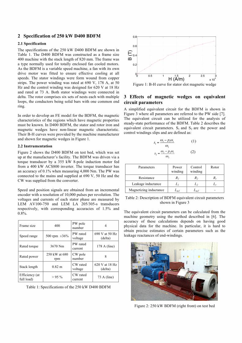
2 Specification of 250 kW D400 BDFM 2.1 Specification The specifications of the 250 kW D400 BDFM are shown in Table 1. The D400 BDFM was constructed as a frame size 400 machine with the stack length of 820 mm. The frame was a type normally used for totally enclosed fan cooled motors. As the BDFM is a variable speed machine, a fan with its own drive motor was fitted to ensure effective cooling at all speeds. The stator windings were form wound from copper strips. The power winding was rated at 690 V, 178 A, at 50 Hz and the control winding was designed for 620 V at 18 Hz and rated at 73 A. Both stator windings were connected in delta. The rotor comprises six sets of nests each with multiple loops, the conductors being solid bars with one common end ring. In order to develop an FE model for the BDFM, the magnetic characteristics of the regions which have magnetic properties must be known. In D400 BDFM, the stator and rotor iron and magnetic wedges have non-linear magnetic characteristic. Their B-H curves were provided by the machine manufacturer and shown for magnetic wedges in Figure 1.
2.2 Instrumentation Figure 2 shows the D400 BDFM on test bed, which was set up at the manufacturer’s facility. The BDFM was driven via a torque transducer by a 355 kW 8-pole induction motor fed from a 400 kW ACS800 inverter. The torque transducer has an accuracy of 0.1% when measuring 4,000 Nm. The PW was connected to the mains and supplied at 690 V, 50 Hz and the CW was supplied from the converter. Speed and position signals are obtained from an incremental encoder with a resolution of 10,000 pulses per revolution. The voltages and currents of each stator phase are measured by LEM AV100-750 and LEM LA 205/305-s transducers respectively, with corresponding accuracies of 1.5% and 0.8%.
Frame size 400 PW pole number 4
Speed range 500 rpm ±36% PW rated voltage
690 V at 50 Hz (delta)
Rated torque 3670 Nm PW rated current 178 A (line)
Rated power 250 kW at 680 rpm
CW pole number 8
Stack length 0.82 m CW rated voltage
620 V at 18 Hz (delta)
Efficiency (at full load) > 95 % CW rated
current 73 A (line)
Table 1: Specifications of the 250 kW D400 BDFM
Figure 1: B-H curve for stator slot magnetic wedge
3 Effects of magnetic wedges on equivalent circuit parameters A simplified equivalent circuit for the BDFM is shown in Figure 3 where all parameters are referred to the PW side [7]. The equivalent circuit can be utilized for the analysis of steady-state performance of the BDFM. Table 2 describes the equivalent circuit parameters. S1 and S2 are the power and control windings slips and are defined as:
(1)
(2)
Parameters Power
winding Control winding
Rotor
Resistance R1 R2 Rr
Leakage inductance L1 L2 Lr
Magnetizing inductance Lm1 Lm2 -
Table 2: Description of BDFM equivalent circuit parameters shown in Figure 3
The equivalent circuit parameters can be calculated from the machine geometry using the method described in [6]. The accuracy of these calculations depends on having good physical data for the machine. In particular, it is hard to obtain precise estimates of certain parameters such as the leakage reactances of end-windings.
Figure 2: 250 kW BDFM (right front) on test bed
0 0.5 1 1.5 2 2.5 3x 10⁴
0
0.2
0.4
0.6
0.8
H (A/m)
B (T
)
s1 =ω1 − p1ωr
ω1
s2 =ω2 − p2ωr
ω2
The equivalent circuit parameters can also be extracted from experimental measurements as described in [7]. Using the parameter values extracted from experimental tests are shown to lead to more accurate predictions [7]. The magnetizing inductances Lm1 and Lm2 are obtained from the magnetizing tests. R1 and R2 are obtained from DC measurements. The rotor parameters Lr and Rr and turns ratio N1/N2 are then obtained from cascade tests using curve-fitting methods [7]. Similar methods can be applied to results obtained from FE analysis in induction and cascade operations to estimate equivalent circuit parameters. Linear and non-linear FE models have been developed for the D400 BDFM in this study. The linear model assumes ideal iron circuit and does not include the magnetic wedges in stator slots, hence the predictions are expected to be close to those from the coupled-circuit model [6]. The non-linear model takes into account the non-linear characteristic of the iron circuit and magnetic wedges in stator slots, i.e. the B-H curves. It will be shown that the predictions from the non-linear model are in close agreement with experimental data. The approaches utilized to obtain the equivalent circuit parameters for the BDFM are summarized in Table 3.
Figure 3: Per-phase equivalent circuit for the BDFM
Iron circuit
Magnetic wedges
Derivation of equivalent circuit parameters
Coupled-Circuit
Linear Not included
From machine’s geometrical data
FE Linear Linear Not included
Lm1 and Lm2 are obtained from induction mode operation
Lr’, Rr’ and N1/N2 are obtained from applying a curve fitting method to cascade data
FE Non-Linear
Non-linear
Included
Experimental tests
Non-linear
Included
Table 3: Different approaches utilized for obtaining the equivalent circuit parameters
3.1 Magnetizing tests When only the PW or CW of the BDFM stator is supplied and the unsupplied winding is left open, the BDFM operates as a P1 or P2 pole pair induction machine, respectively. If the rotor speed is set to the synchronous speed using an external load
machine, the equivalent circuit of Figure 3 will reduce to only include the supplied winding’s resistance and magnetizing inductance. The magnetizing characteristics of the D400 BDFM are shown in Figures 4 and 5 for the two stator windings. Results from experiments and FE linear and non-linear models are shown. The supply frequency was 20 and 10 Hz for the PW and CW magnetizing tests respectively. The solid horizontal lines show the rated voltage of the corresponding winding at the excited frequency.
Figure 4: Magnetizing characteristic of the stator PW
Figure 5: Magnetizing characteristic of the stator CW
As can be seen from Figures 4 and 5, the magnetizing characteristics are linear below the rated voltage where the effect of iron saturation is not significant. In addition, the effect of stator slot magnetic wedges on reducing magnetizing currents is evident. The magnetizing inductances, Lm1 and Lm2 can be obtained from the slope of the linear region below the rated voltages and are shown in Table 4.
Experiment FE Non-Linear
FE Linear Couple Circuit
Lm1 (mH) 104 98 84 82.7
Lm2 (mH) 368 341 287 276
Table 4: Magnetizing inductances obtained at the rated air gap flux density
3.2 Cascade tests The rotor parameters, Lr and Rr and turns ratio N1/N2 may be obtained by applying a curve fitting method to results from BDFM cascade operation. The stator currents (both supplied and shorted windings) and torque are used for extracting the parameters. The fitting algorithm assumes fixed values for stator winding resistances R1 and R2, and magnetizing
I1 R1 jω1Lr Rr /s1 Ir R2s2s1 I2
s2s1 2Vjω1Lm2jω1Lm1nV1 ,ω1
n n n
n
n n
n
0 20 40 60 80 1000
200
400
600
4p magnetizing Current4P
Vol
tage
(V)
Rated 4−pole flux densityRated air−gap flux densityFE Non− linearFE Linear
inductances Lm1 and Lm2 and finds values for Lr, Rr and N1/N2 which give the best fit. The cascade tests have been carried out at low voltages due to restriction on stator currents, hence the extracted parameters do not represent the effect of iron saturation.
3.3 Equivalent circuit parameter values The extracted equivalent circuit parameter values from coupled-circuit model and FE linear model are shown in Table 5. As can be seen, there is close agreement between the parameters obtained from the two methods which shows that the assumptions to obtain the coupled-circuit model and its transformation to equivalent circuit model proposed by Roberts in [6] lead to acceptable accuracy. Nevertheless, neither of the models can take into account the effect of saturation and magnetic wedges.
Table 6 shows the extracted paramerets from the experimental measurements and FE non-linear model, which takes into account the effects of iron saturation and magnetic wedges. There is close agreement between the parameters extracted from the two methods. As mentioned, since the tests were carried out at low supply voltages, the effects of iron saturation are negligible, hence the differences seen in the parameters including the magnetizing inductances Lm1 and Lm2 and rotor inductance Lr between Tables 5 and 6 are mostly due to the effects of magnetic wedges. When magnetic wedges are present, the magnetizing inductances are larger due to the effect of wedges in closing the air gap. The rotor inductance is also larger which is most likely due to higher flux leakage.
R1
(mΩ) Lm1
(mH) Rr
’
(Ω) Lr
’
(mH) R2
(mΩ) Lm2
(mH)
Coupled Circuit 0.0907 82.7 0.110 8.88 0.667 276
FE – linear 0.0971 84.2 0.116 9.40 0.706 285
Difference (%) 7.1% 1.8 % 5.5 % 5.8 % 5.8% 3.3 %
Table 5: Equivalent circuit parameters extracted from coupled-circuit and FE linear models. Both models do not
take into account the effects of iron saturation and magnetic wedges
R1
(mΩ) Lm1
(mH) Rr
’
(Ω) Lr
’
(mH) R2
(mΩ) Lm2
(mH)
Experiment 0.0971 104 0.114 12.45 0.706 368
FE – nonlinear 0.0971 97.1 0.122 14.3 0.706 341
Difference (%) - 6.6% 7% 14.9% - 7.3%
Table 6: Equivalent circuit parameters extracted from the FE non-linear model and experimental measurements. The non-linear model takes into account the effects of iron saturation
and magnetic wedges
4 Conclusions The effects of magnetic wedges on the performance of the BDFM have been investigated by analysing their impacts on the machine’s equivalent circuit parameters. It has been shown that the magnetizing currents are reduced with magnetic wedges, and hence the stator magnetizing inductances are increased. The rotor inductance is increased as a result of using magnetic wedges, mostly due to increase in the winding leakage inductances, which will have effects on the machine’s torque characteristics, reactive power management and converter rating requirement. The predictions from FE models have been verified experimentally, which shows the efficacy of the modelling approach in the analysis of BDFM performance.
Acknowledgement The research leading to these results has received funding from the European Union's Seventh Framework Programme managed by REA – Research Executive Agency http://ec.europa.eu/research/rea (FP7/2007_2013) under Grant Agreement N.315485.
References [1] H. Arabian-Hoseynabadi, H. Oraee, and P J Tavner. Wind turbine productivity considering electrical subassembly reliability. Renewable Energy, 35:190–197, (2010). [2] R. Carlson, H. Voltolini, F. Runcos, P. Kuo-Peng, and N. Baristela, “Performance Analysis with Power Factor Compensation of a 75 kW Brushless Doubly Fed Induction Generator Prototype’, IEEE International Conference on Electric Machines & Drives, Antalya, Turkey, vol. 2, pp. 1502–1507, May (2007). [3] R. A. Hanna, W. Hiscock, and P. Klinowski, “Failure analysis of three slow-speed induction motors for reciprocating load application,” IEEE Transactions on Industry Applications, vol. 43, no. 2, pp. 429 – 435, (2007). [4] H. Liu and L. Xu, “Design and performance analysis of a doubly excited brushless machine for wind power generator application,” IEEE International Sympousiom on Power Electronics for Distributed Generation Systems, China, pp. 597–601, (2010). [5] R. A. McMahon, E. Abdi, P. Malliband, S. Shao, M. E. Mathekga, and P. J. Tavner, “Design and testing of a 250 kW Brushless DFIG,” 6th IET International Conference on Power Electronics, Machines and Drives (PEMD), Bristol, UK, pp. 1-6, March (2012). [6] P. C. Roberts, A Study of Brushless Doubly-Fed (Induction) Machines. PhD thesis, University of Cambridge, (2004). [7] P. C. Roberts, R. A. McMahon, P. J. Tavner, J. M. Maciejowski, and T. J. Flack. “Equivalent circuit for the brushless doubly fed machine (BDFM) including parameter estimation and experimental verification,” IEE Proceedings of the Electrical Power Applications, 152:933–942, (2005). [8] Y. Takeda, T. Yagisawa, and M. Yamamoto, “Application of magnetic wedges to large motors,” IEEE Transactions on Industry Applications, vol. MAG-20, no. 5, pp. 1780–1782, (1984).