BSEE Panel Report 2017-002 Investigation of March 10, 2016, Fatality Lease OCS-04940, Green Canyon Area- Block 18 Gulf of Mexico Region, Houma District Off Louisiana Coast March 8, 2017 U.S. Department of the Interior Bureau of Safety and Environmental Enforcement
Transcript
BSEE Panel Report 2017-002
Investigation of March 10, 2016, Fatality Lease OCS-04940, Green Canyon Area- Block 18
Gulf of Mexico Region, Houma District Off Louisiana Coast
March 8, 2017
U.S. Department of the Interior Bureau of Safety and Environmental Enforcement
Figure 1: Location of Lease OCS-G 04940, Green Canyon Area, Block 18. ........................................ 6 Figure 2: Whistler’s Green Canyon 18 “A” Platform with Nabors MODS 201 Platform Drilling Rig Installed. ................................................................................................................................................. 7 Figure 3: Structure of Onsite Drilling Crew (Based upon information provided by both Whistler and Nabors). .................................................................................................................................................. 8 Figure 4: (Partial) Representative Illustration of Nabors MGS. ............................................................. 9 Figure 5: Photograph of the MGS on the Rig. ...................................................................................... 10 Figure 6: Depiction of approximate Dimensional Relationships between the MGS, its Inspection Hatch and the Chipping Tool. .............................................................................................................. 12 Figure 7: Wellbore Schematic Depicting the Six Different Cementing Operations............................. 16 Figure 8: Image Attached to a March 6, 2016, Email Depicting the "CMT" from the Casing Valve. . 19Figure 9: Wellbore Schematic Depicting CBL Results. ....................................................................... 21 Figure 10: Representation of the BOP and the Bleed Paths. ................................................................ 23 Figure 11: Photographs of the Viewpoint through the MGS Inspection Hatch Opening after the Inspection Hatch Cover was Removed (Taken by the RM). ................................................................ 24 Figure 12: At approximately 07:04, the DH arrives on the Rig Floor in Unsoiled PPE with a Bucket to begin the Process of Cleaning the MGS (still image from rig video). ................................................. 25 Figure 13: At approximately 07:07, the DH’s Body Position and Movements Appeared Consistent with that of a Person who might be Reaching into the MGS with their Right Arm (still image from rig video). ................................................................................................................................................... 26 Figure 14: At approximately 07:10, The DH Approached and Engaged with the RM with Readily Apparent Discoloration (soiling) up the Right Arm and Right Side of the PPE (still image from rig video). ................................................................................................................................................... 26 Figure 15: At approximately 07:11, the DH and the RM walk over to the MGS Inspection Hatch (still image from rig video). .......................................................................................................................... 27 Figure 16: At approximately 07:46, the DH Walks Down the Stairs and off the Rig Floor in the Soiled PPE. This was the Last Time this Light Colored PPE was observed on the Rig Floor (still image from rig video). ............................................................................................................................................. 27 Figure 17: Post-Incident Photograph of the chipping tool. .................................................................. 28 Figure 18: Post-Incident Photographs of the MGS Section of 8” Drain Outlet Piping after Cutting and Removal................................................................................................................................................ 30 Figure 19: Excerpt from page 1 of the March 10, 2016, JSA Document as it was provided Post-Incident. ................................................................................................................................................ 32 Figure 20: Excerpt from page 3 of the March 10, 2016, JSA Document as it was provided Post-Incident (with added highlights). .......................................................................................................... 34 Figure 21: Excerpt from the March 10, 2016, PTW Document as it was provided Post-Incident (with added highlights and redactions by BSEE). ......................................................................................... 36 Figure 22: Excerpt from the March 10, 2016, HWP Document as it was provided Post-Incident (with added highlights and redactions by BSEE). ......................................................................................... 37 Figure 23: Depiction of the Task-level documents and their Required Signatory Approval Authorities. .............................................................................................................................................................. 37 Figure 24: Pre-Incident Photographs of Viewpoint through the Inspection Hatch into the MGS (taken by the RM)............................................................................................................................................ 39 Figure 25: Post-Incident Photograph of Viewpoint through the Inspection Hatch into the MGS (taken by the RM)............................................................................................................................................ 39
iii
Abbreviations and Acronyms
AD– Assistant Driller APR– Annual Performance Review ASP– Air-medical Service Provider BOP– Blowout Preventer BSEE– Bureau of Safety and Environmental Enforcement CBL– Cement Bond Log CFR– Code of Federal Regulations CPR– Cardiopulmonary Resuscitation CSE– Confined Space Entry DH—Derrick Hand GC– Green Canyon HWP– Hot Work Permit HSE– Health Safety and Environmental JSA– Job Safety Analysis KWM– Kill Weight Mud MD– Measured Depth MODS– Modular Offshore Dynamic Series Medevac– Medical Evacuation MGS– Mud/Gas Separator OA– Operations Assistant OCS– Outer Continental Shelf OSHA– Occupational Safety and Health Administration PIC–Person in Charge PPE– Personal Protective Equipment Ppg– Pounds per Gallon Psi– Pounds per Square Inch PTW– Permit to Work RM– Rig Manager SEMS– Safety and Environmental Management Systems SICP– Shut-in Casing Pressure SimOps– Simultaneous Operations SWA– Stop Work Authority SWP—Safe Work Practice TOC– Top of Cement TS– Task-level Supervisor USCG– United States Coast Guard UWA– Ultimate Work Authority WSS– Well Site Supervisor
1
Executive Summary
On March 10, 2016, an Assistant Driller (AD) for Nabors Offshore Corporation (“Nabors”), was fatally injured as a result of traumatic injuries incurred while performing assigned work to remove material from the drilling rig’s vertical Mud/Gas Separator (MGS or “gas buster”). This material, believed by the Nabors drilling crew to be cement (“the material” or “cement”), was the result of a recent cement job(s). The material was discovered inside the MGS as the result of troubleshooting difficulties encountered during Blowout Preventer (BOP) system pressure testing in the days prior. The material accumulation inside of the MGS had already begun to cure and harden when it was found.
At the time of the incident Nabors was performing drilling operations for Whistler Energy II, LLC (“Whistler”) under their contractual agreement. Whistler’s actual drilling progress exceeded 120 days, nearly doubling the planned drilling program, and was projected to be about $9.4 million over budget. Drilling operations required a functioning MGS; therefore, it was necessary to either remove the obstructing material or replace the MGS. While other operations were suspended due to adverse weather, and knowing that medical evacuation transportation would be unreliable, a facility-level supervisor approved and assigned the non-routine task to remove the material from the MGS (“the task”) and replace the MGS if the task proved unsuccessful.
The Nabors personnel assigned to the task were instructed by facility-level supervisors, on this second day of the task, not to place any part of their body into the MGS, for any reason, and were then primarily equipped with an improvised 45 inch-long chipping tool to accomplish the removal of the material via a 14 inch inspection hatch opening and 8 inch drain line opening (which were both located on the lower portion of the 16 foot tall MGS). In other words, the primary tool used for the task and the method being used to remove the material, would preclude task completion without physical entry into the MGS.
The extent of the material accumulation inside the MGS was not known; however, it was assumed by some personnel, including the driller who was the Task-level Supervisor (TS), that the MGS had accumulated enough of the material to have reached the height of its internal baffles. Another assumption was made that the baffles inside the MGS would support and prevent the material from falling once the supporting lower portion of the material was removed.
The vast majority of personnel involved with the task, including the TS, reached into and/or stuck their heads inside the MGS in performance of the task. Despite some personnel assigned to the task having individual concerns about the working conditions, none of the personnel exercised their stop work authority. After returning from lunch, the AD was critically injured while working with a portion of his upper body inside of the MGS.
2
The traumatic injuries sustained by the AD were a direct result of the uncontrolled physical hazard (the material) falling onto and entrapping the AD’s head and right arm at the inspection hatch access into the MGS. The AD was eventually extricated and first response medical care efforts were promptly initiated. The AD was resuscitated and then monitored while emergency response resources were coordinated.
Emergency response and evacuation transportation vessel resources had been, and remained, unavailable due to the adverse weather conditions. Unanticipated setbacks with the helicopter transportation resource delayed its response time. Once evacuated, and while in transport to an onshore medical center, the AD’s vital signs diminished. The AD was pronounced dead following evaluation at the medical center. The Coroner’s report classified the death as “Accident” and diagnosed injuries consistent with that of witness observations and other information provided to the Bureau of Safety and Environmental Enforcement (BSEE) investigation panel.
BSEE convened a panel to conduct an investigation into the cause(s) of the fatal incident. The panel, comprising BSEE professionals, identified the following direct and indirect incident-causal-factors that may have contributed to the direct causation and totality of the incident:
Direct Cause
· The traumatic injuries sustained were a direct result of physically entering into the MGS when performing assigned work while the known physical hazard remained uncontrolled.
Probable Contributing Causes
· Supervisors did not fulfill their respective responsibilities within the relevant, established Safe Work Practices (SWPs)1 when authorizing the task and supervising the task-work.
· Supervisors and personnel alike did not adhere to the verbal work instructions and relevant, established SWPs while performing the task-work.
· Surface equipment was not adequately flushed to remove all of the contaminating material from all affected equipment.
1 SWPs encompass Health, Safety and Environmental (HSE) –Policies, Procedures and Work Instructions.
3
Possible Contributing Causes
· Deficient corrective actions for the task-level hazard analysis non-conformances identified during a Safety and Environmental Management Systems (SEMS) audit.
· Cement from the intermediate casing cement job and/or annulus squeeze plug cement job contaminated the MGS.
· Compartmentalized task-level work permitting process.
· Inefficient emergency medical resource activation process.
· Lack of detail within Job Safety Analysis (JSA) procedures regarding critical elements and certain responsibilities.
· Financially induced pressure to complete the well.
The BSEE Panel makes recommendations in an effort to further promote safety, protect the environment, and conserve resources on the U.S. Outer Continental Shelf (OCS). The following listing contains some of the key recommendations identified as a result of the investigative findings detailed within this report:
· Supervisory personnel should ensure task-related paperwork adheres to established SWPs and work instructions and also ensure personnel follow those SWPs and work instructions by taking an active role in the task planning and supervision, modeling safe behavior, and holding those accountable who do not act accordingly.
· Hazard analyses and associated work permits should be meaningful and should be updated or revised to reflect all impactful changes in the task conditions and/or the working environment.
· Training programs and SWPs should be consistent and clear to reduce the risk of a misunderstanding.
· Emergency response plans and supporting response organization agreements should be evaluated to ensure everything is adequately in place to support emergency response plans and strategies.
· Equipment maintenance should be sufficient to ensure all impacted equipment is adequately flushed to prevent equipment damage when cement is circulated to the surface.
4
Introduction
Authority
Pursuant to 43 U.S.C. § 1348(d)(1), (2) and (f) [Outer Continental Shelf Lands Act, as amended] and 30 CFR Part 250 [Department of the Interior regulations], the Bureau of Safety and Environmental Enforcement is required to investigate and prepare a public report of this incident.
BSEE’s Gulf of Mexico (GOM) OCS Region, Houma District office was notified of the Incident on March 10, 2016. By memorandum dated March 11, 2016, the investigation panel (“the panel”) was formed and initiated its investigation of the incident. The panel included:2
Andrew Black – Chairman, Special Investigator, Safety & Incident Investigations Division, Headquarters;
Troy Boudreaux – Inspector, Well Operations Inspection Unit, Houma District, GOM, OCS Region;
Harold Griffin – Petroleum Engineer, Office of Incident Investigations, GOM, OCS Region;
James Richard – Inspector/Accident Investigator, Well Operations Inspection Unit, Houma District, GOM, OCS Region.
2 United States Coast Guard (USCG) Investigating Officer, Lieutenant Christopher Mosquera participated in the initial stages of the investigation until the lead investigating agency (BSEE) was determined.
5
Investigation and Process
The purpose and scope of the investigation was to identify the direct and indirect causes of the operational incident which resulted in a fatality and to make recommendations from the investigative findings to reduce the likelihood of a recurrence or similar incident. The panel identified what it believes to have directly caused the incident as well as indirect factors which may have contributed to the totality of the incident. In this report, the panel distinguished indirect contributing causal factors as either probable or possible contributing causes.
The investigation process consisted of ordering the preservation of the incident scene and all potentially relevant information, and included site visits, individual witness interviews, requests for documentation and extensive documentation review. The document requests were focused to accomplish the following investigative goals:
· Understanding the operational chain of events leading up to the incident, the incident, and the response to the incident.
· Identifying the activities of Whistler and its contractors relative to the operational incident and its surrounding events.
· Comparing the actions of each relevant contractor involved to the standard of safety and performance established and agreed upon by both Whistler and each contractor performing operations on its behalf and as documented in their SEMS Bridging Agreements.
· Reviewing the SWPs and training curriculum correlative to the work being performed at the time of the incident.
6
Background
The AD was working aboard Nabors Modular Offshore Dynamic Series™ (MODS) –201 platform drilling rig (“the rig”) which was temporarily installed on Whistler’s “A” Platform (“the platform”) at the time of the incident. The Green Canyon (GC) Block 18 facility (“the facility”) comprises both the rig and the platform. The rig was contracted to Whistler, to conduct platform drilling operations within the GC Block 18 lease, OCS-G 04940 (“the lease”).
The lease covers approximately 5,760 acres on the OCS, within the GOM, off the Louisiana coast (see Figure 1). The lease was purchased in 2013 by Whistler as the 100 percent working interest owner. Whistler, as the lessee and designated operator, was responsible for ensuring all operations performed at the facility were conducted in compliance with all applicable regulations.
Figure 1: Location of Lease OCS-G 04940, Green Canyon Area, Block 18.
The GC Block 18 Facility
The Platform: is a six-legged, sixteen pile, fixed steel structure with thirty well slots (see Figure 2). It was originally installed in 1986 by Mobil Oil Exploration and Producing Southeast, Inc., and was purchased by Whistler in 2013. The water depth at the GC Block 18 location is ~750 feet, and the distance from shore is ~96 miles. Twenty-nine of the thirty well slots have been drilled, with eight wells producing at the time of the incident.
7
The Rig: is a platform drilling rig (see Figure 2) owned by Nabors. The rig was constructed in 2004 and is rated to a drilling depth capability of 25,000 feet. The rig was installed at the GC Block 18 location in September 2015 and was operating under its platform drilling contract with Whistler, to drill a slot recovery development well using the previously abandoned A-13 well slot (“the well”). The incident occurred during operations related to the well slot-recovery drilling program.
Companies Involved
Whistler used contractors to perform all of its operations. At the time of the incident, a total of 78 contractor personnel from 17 different companies were aboard the facility. The primary contracted service provider companies involved with relevant operations were:
· Nabors Offshore Corporation, for drilling operations, · Progressive Global Energy, for Whistler’s day-shift company representation
(“Well Site Supervisor (WSS) or Ultimate Work Authority (UWA)”), · Hyperion Safety Services LLC, for Health Safety and Environmental (HSE) and
Simultaneous Operations (SimOps) coordination, · Wood Group PSN (“Wood Group”), for production operations and emergency
evacuation and response coordination, · Halliburton Energy Services Inc., for cementing operations; and · Premiere Fluids, for drilling and completion fluid services.
Figure 2: Whistler’s Green Canyon 18 “A” Platform with Nabors MODS 201 Platform Drilling Rig Installed.
MODS 201 Rig
8
Drilling Operations
Whistler’s drilling operations were conducted on a 24-hour basis using two primary 12-hour shifts, with shift changes scheduled at 06:00 (day shift) and 18:00 (night shift). The day shift WSS was tasked as the UWA for the entire GC Block 18 facility. The Rig Manager (RM) was responsible for overseeing the day-to-day drilling operations (organizing, delegating, and supervising the rig activities).
Whistler and Nabors documentation collectively depicted the relevant GC Block 18 onsite facility-level Well-Ops [Drilling] supervision and organizational structure as the following: (see Figure 3).
Figure 3: Structure of Onsite Drilling Crew (Based upon information provided by both Whistler and Nabors).
9
Relevant Drilling Equipment
Mud Gas Separator: Drilling equipment can be severely affected by “gas cutting,” a condition in which gas becomes mixed or entrained in drilling fluid (mud) or other liquids. Gas cutting reduces the density of liquids, and significant gas cutting may displace liquids to the surface, reducing bottom-hole pressure to the point that well control may be lost. For these reasons, it is necessary to employ equipment used to separate mixed or entrained gas from liquids. The basic equipment for handling gas-cutting includes: gas busters, mud gas separators, and degassers (see Figure 4).
Figure 4: (Partial) Representative Illustration of Nabors MGS.
10
The Rig’s vertical MGS (see Figure 5) was ~16 feet tall and was designed with numerous internal baffles to separate the liquids from gasses. Under normal operating conditions, separated gasses would vent through the 10 inch vent outlet at the top of the MGS, and the remaining liquids would drain through the 8 inch drain outlet at the bottom. The MGS was located between the choke manifold and the cement manifold on the southeast corner of the rig’s upper deck. The MGS was designed and fabricated by Nabors.
Figure 5: Photograph of the MGS on the Rig.
MGS
Incident location area
11
Timeline
The following chronology was developed from a combination of documentation and witness accounts provided to the panel, throughout the course of its investigation into the March 10, 2016 incident:
March 1-6, 2016, two cement jobs (the intermediate casing and annulus squeeze plug, respectively) were conducted. The intermediate casing cement job proved unsuccessful (which was indicated by a consistent increase in casing pressure), and was followed by an attempt to “kill” the well by bullheading using kill weight mud.3 Ultimately, an annulus squeeze plug cement job was performed. During this second cement job, cement was documented to have been observed flowing through the casing valve at a steady rate (estimated at 1 barrel per hour). The BOP stack was then drained and flushed with sugar-water (a retarder used to slow the cement curing process). The well continued to be monitored and flow was, once again, observed at the casing valve (estimated at .5-1 gallon per hour). Although the annulus cement plug was not set at its planned and approved depth, (due to reaching the maximum pressure prematurely), the well was eventually deemed to be static.
On March 7, 2016, BSEE inspectors issued an Incident of Non Compliance to Whistler for failing to follow their approved permit regarding the setting depth of the annular cement plug. The annular plug was only pumped to an estimated 2,203 feet instead of the permitted depth of 5,900 feet.
On March 8, 2016, Nabors drilling crew attempted to drain and flush the MGS and began performing a required periodic BOP system pressure test. During test #6 of the BOP testing sequence (choke manifold), the Nabors drilling crew documented encountering “restrictions.”
March 9, 2016, while troubleshooting the cause of the difficulties encountered during the BOP system testing, material was discovered inside the rig’s vertical MGS via its inspection hatch. The material had built-up inside the MGS and was in the process of curing. Without fully understanding the extent of the material buildup, the RM assigned the task to the work crew. A hammer and chisel were the tools approved and identified on the Job Safety Analysis (JSA) document for chipping the material into fragments to allow for the material removal by way of the MGS inspection hatch opening. By mid-day shift, the hammer and chisel were replaced with a pneumatic chisel that had been affixed to a wooden pole with zip ties (“the chipping tool”).
Work to remove the material from the MGS continued into and through the night shift and included the removal of a section of the MGS’s drain pipe which created an 8 inch opening allowing for material collection and removal via the bottom of the MGS.
3 “Bullheading” involves pumping specific volumes of heavyweight “kill” mud into the well, without circulation, in order to force formation fluids back into the formation.
12
March 10, 2016, the day shift, facility-level morning safety meeting occurred. During that meeting, the AD led a discussion covering the topic of Stop Work Authority (SWA) and facility-level supervisors gave explicit instructions to personnel not to physically enter into the MGS (i.e. place any part of the body inside), for any reason. Additionally, weather conditions and their adverse impacts on emergency response transportation were emphasized during this meeting.
After the facility-level safety meeting, the Task-level Supervisor (TS) and eleven personnel, (“the work crew”), were assigned to perform the task and relieve the night-shift work crew. Prior to beginning the task work, the work crew attended a specific task-level JSA meeting. The focus of the JSA meeting was the task-level JSA document. The JSA document’s job-steps were an exact copy of the job-steps specifically developed for the task, when the task originated. The JSA’s documented job-steps had not been updated to reflect the changed tools and conditions, of the progressing task.
Specifically, the JSA document did not list the pneumatic chipping tool being used for the task nor did it take into account unique hazards associated with its use. More specifically, the analysis of the task did not contemplate the limitations imposed by the 45 inch length of the rigid chipping tool as it related to the assignment of cleaning the interior of the 47 inch by 16 foot vertical MGS with internal baffles, through its 14 inch inspection hatch and 8 inch drain line openings (see Figure 6).
Figure 6: Depiction of approximate Dimensional Relationships between the MGS, its Inspection Hatch and the Chipping Tool.
13
Nabors’ SWPs required a Permit to Work (PTW) and Hot Work Permit (HWP) for the task, in addition to the JSA. The JSA, PTW and HWP had all received the requisite approval signatures for authorizing the task work. The PTW indicated hot work and therefore required special consideration be given regarding confined space, when completing the PTW. The associated HWP affirmatively indicated that confined space was not applicable.
Both the WSS and the Production Person-in-Charge (PIC) signed and approved the HWP, signifying verification of permit conditions and authorizing the task work to begin. The Production PIC stated he did not visit the task site prior to signing the HWP, and no information was provided to the panel indicating the WSS visited the task site either, prior to signing the HWP. In addition, the TS was not required to complete, sign, or approve the PTW or HWP and did not review either of these unique task specific documents.
The RM documented a specific warning in his tally book that personnel were, “not to stick head or arms inside gas buster due to the possibility that the cement block could fall,” indicating this had been discussed during the pre-tour, facility-level safety meeting. In contrast to this warning, on rig video, the RM appears to take off his hard hat and stick his head inside the MGS in the view of work crew members, at the beginning of the day shift.
Accordingly, the vast majority of personnel assigned to the task, including the TS, admittedly physically entered the MGS when reaching into and/or looking into the MGS while performing the task throughout the morning and into the afternoon. Even though physical entry into the MGS went against the specific verbal directive to not physically enter into the MGS, there were no indications that any personnel invoked SWA at any point during the task.
After returning from lunch, the AD physically entered into the MGS through its inspection hatch opening. While working with the makeshift chipping tool, and with his head and right arm inside the MGS, overhead material dislodged and/or broke free, fell, and entrapped the AD’s head and an arm inside the MGS. Once nearby personnel recognized the AD was in distress, they began attempting to extricate the AD from the MGS. Steps were also taken by personnel to clear away any debris that may have been obstructing the drain line opening at the bottom of the MGS (to ensure an airway was available), while other personnel notified facility-level supervisors.
Personnel continued efforts to extricate the AD from the MGS, a process which took approximately eight minutes. Upon extrication, the AD was unresponsive and personnel immediately laid him on the rig floor. Personnel retrieved and utilized available medical equipment and Cardiopulmonary Resuscitation (CPR) was performed. The AD was resuscitated and oxygen was provided through a mask while care continued. The Operations Assistant (OA) contacted an Air-medical Service Provider (ASP) to initiate an emergency medical evacuation (“medevac”) response and medical professionals were consulted remotely.
14
When requesting the medevac, personnel involved with coordinating the emergency response realized that a “mandatory” mission and payment authorization form (“landing paper”), was required to be completed. The landing paper was signed by the WSS and submitted to the ASP, prior to the medevac aircraft launching. At the time of the medevac aircraft launch, approximately 59 minutes had elapsed from the time of the incident.
The initial medevac response aircraft crew encountered difficulties with the aircraft’s equipment while traveling to the facility and returned to shore to switch out its aircraft. The USCG was then notified and the ASP switched its medevac response aircraft. Once notified, the USCG sent one of its aircraft to back up the ongoing emergency response efforts. At the time of the ASP’s on-scene arrival, approximately 3 hours had elapsed. The AD was evacuated from the facility and while in route to the hospital, the AD’s vital signs diminished. The AD was pronounced dead following evaluation at the medical center.
Red marking tape was used to cordon off the rig floor and preserve the incident scene area after the medevac was completed. The panel conducted its initial visit to the facility on March 13, 2016.
15
The BSEE Investigation
The BSEE investigation process included ordering Whistler and its contractors to take all steps necessary to immediately identify, retain, and preserve all potentially relevant information related to the incident. The BSEE panel conducted multiple site visits, numerous witness interviews and requested and reviewed large volumes of documentary materials. The documentation provided by Whistler and its contractors included, but was not limited to, safety and environmental management systems, safe work practices, policies, procedures, equipment design and maintenance records, training records, audio and video recordings and communications. The following represents key focus areas and relevant findings identified during the investigation.
Cement Contamination of MGS
In offshore drilling operations, cementing is used for several general purposes, including zone isolation, corrosion control, and formation stability. Cement is also used to fill and seal the annulus between the casing string and the drilled hole. Under normal conditions, cement flow is not routed through the MGS.
Whistler’s initial assessment of the cause of cement contamination concluded that the most likely cause of the cement contamination of the MGS resulted from the 9-5/8 inch Intermediate Casing Cement Job. Whistler deemed it “highly unlikely” that it occurred during the subsequent Annulus Squeeze Plug Cement Job, citing the following:
1. The “bullhead” work did not pass through the MGS
2. Multiple valves would have had to be aligned in such a way to flow through the MGS, which would have been noted immediately by the cementer and supervisor monitoring the job
3. The cement pumped did not have gas entrained in it
During the permitted drilling operations for the well, cementing operations were conducted on six occasions (see Figure 7). Based upon the timeline of events and normal cement curing times, only the 9-5/8 inch intermediate casing and subsequent annulus squeeze plug cement jobs were evaluated. Therefore, the first four cementing jobs were not considered relevant in the analysis of cementing operations.
16
Figure 7: Wellbore Schematic Depicting the Six Different Cementing Operations.
17
9-5/8” Intermediate Casing Cement Job
Whistler’s Drilling Prognosis called for drilling to a Measured Depth (MD) of 13,481 feet and setting the 9-5/8 inch intermediate casing string. The cement job for this casing string was planned to be pumped down the wellbore and up into the annulus to a MD of 8,000 feet.
March 1, 2016, Nabors completed running the casing string to a MD of 13,521 feet. While Halliburton rigged up equipment to pump the cement. The driller continued circulating drilling fluids in the well, and during this process the well began “taking” fluids at a rate of about 24 barrels per hour, indicating a loss of fluids to the formation.
Once rigged up, Halliburton started pumping 60 barrels of spacer (15.7 pounds per gallon (ppg)) followed by 388.88 barrels of cement (16.4 ppg). This was followed up by 10 more barrels of spacer and the top plug, or cement dart. Nabors then pumped 938 barrels of mud (15.2 ppg), but were unable to “bump the plug” (meaning the cement did not reach its intended depth, which resulted in a lower height of cement in the annulus). In addition, the mud returns observed during the cement job indicated a mud loss of 24 percent.
At 22:00, Halliburton completed the cement job, bleeding back 3.5 barrels with the float holding. Nabors then closed the annular BOP, maintained 200 pounds per square inch (psi) on the annulus using the choke manifold, and waited on cement.
March 2, 2016, at 09:30, pressure was bled off in order to open the annular BOP and monitor the well. Mud returns were received at a rate of 6.5 barrels per hour. Between the hours of 18:00 and 22:00, the rate of mud returns slowed to 5 barrels per hour. The annular BOP was then closed, thereby preventing further back flow through the well bore. Nabors continued to monitor the pressure in the annulus using the choke panel.
March 3, 2016, by 06:00 Nabors had bled pressure 28 times, from the time the annular was closed the day prior, by opening the hydraulic control remote valve on the choke line until the annulus pressure, also known as Shut-In Casing Pressure (SICP), was zero. During this process, the SICP was allowed to increase to 500 psi, at which point it was bled-off to reduce the pressure. The mud that was bled-off during the process was entrained with gas and was routed through the MGS prior to returning to the trip tank. The frequency of bleeding off pressure had increased from once every hour to once every 2-3 minutes during this process.
This bleeding process continued throughout the morning and early afternoon, with the SICP increasing to as high as 1480 psi at one point. At about 13:30, Nabors commenced bullheading operations using 17.0 ppg Kill Weight Mud (KWM) in an attempt to “kill” the well. By 22:00, Nabors had “bullheaded” the annulus six times using a total of 100 barrels of KWM. This bullheading operation momentarily decreased the SICP. At 22:15, the SICP began increasing again. Around that time, BSEE’s Houma District approved the use of an
18
annulus cement plug, with the planned Top of Cement (TOC) to be at a MD of 5,900 feet and the planned bottom of cement to be at a MD of 7,320 feet.4
March 4, 2016, by 08:30 the SICP reached 890 psi, and Nabors attempted another “bullhead” of 85 barrels of KWM into the annulus. Again, the bullheading momentarily decreased the SICP to zero at 11:20. At 17:30, the SICP began increasing once again.
Annulus Squeeze Plug Cement Job
March 5, 2016, by 03:00, the SICP reached 260 psi, and was bled off to zero. Halliburton then pumped 100 barrels of KWM into the annulus, increasing the SICP to 3,280 psi. Once pressure decreased to 3,000 psi, Halliburton began pumping 10 barrels of spacer (15.7 ppg).
At 08:00, Halliburton began pumping 79 barrels of cement (16.4 ppg), containing a retarding additive. The cement was followed up by five more barrels of spacer and 123 barrels of mud (15.2 ppg). The cement unit was used to pump cement until the annulus reached pressures between 3,000 – 3,500 psi, at which point the pumps were shut down until the pressure decreased to 600 psi. This pumping process was repeated until the entire volume of cement was pumped. This process took about six hours. Based on the volume of displacement behind the cement, Whistler estimated that the MD of the TOC was 2,203 feet (the annulus cement plug was approved with the planned TOC to be at a MD of 5,900 feet). The annulus cement plug was not pumped to its planned and approved depth due to reaching the maximum pressure prematurely.
March 6, 2016, while waiting for the annulus plug cement to cure, the SICP increased to 460 psi. Nabors continued to bleed off pressure in the same manner described following the unsuccessful intermediate casing cement job. Once the pressure was bled to zero psi, Nabors opened the annular BOP and noted a gain of three barrels. The annular BOP was closed, after which the SICP rose to 10 psi. Nabors continued the bleeding process, allowing the pressure to build, and bleeding it off about every 10 psi. At around 15:30, the SICP was zero.
While this process was taking place, the Mud Engineer realized that “light flow” was coming through the casing valve. The flow returns were sampled and confirmed to be cement (see Figure 8). The flow path for the cement went through the casing valve, up to the cement manifold, through the choke manifold, and through the MGS on its way to the mud pits.
At about 16:30, the well was deemed static.
At about 17:00, the BOP was drained and flushed with sugar water.
4 Halliburton did not commence the approved annulus cement plugging operation until March 5, 2016.
19
Figure 8: Image Attached to a March 6, 2016, Email Depicting the "CMT" from the Casing Valve.
Nabors continued to monitor the well and around 18:30 recorded mud returns at the casing valve (with a mud weight range from 11.7 to13.1 ppg) at a rate range of 0.5 to 1 gallon per hour according to the daily drilling report.
At 20:00, a decision was made that the well was “dead” according to the mud report.
Source of MGS cement contamination
The intermediate casing cement job concluded on March 3, 2016, and the annulus squeeze plug cement job concluded on March 5. At the time of the discovery of the material accumulation inside the MGS on March 9, both cement jobs had exceeded typical cement curing times of 8 to 12 hours.
During the intermediate casing cement job, Nabors was bleeding off gas-entrained mud through the MGS and there were no signs of any restrictions. This indicates that the cement that blocked flow through the MGS did not come from a prior cement job.
During the subsequent annulus squeeze plug cement job, Nabors was bleeding off mud through the MGS and there were no signs of any restrictions. This indicates that the cement, which restricted flow through MGS, was not present at that point in time and did not come from the preceding intermediate casing cement job.
Third-party cement bond log
A Cement Bond Log (CBL) was performed by a third-party on June 18, 2016, to evaluate isolation integrity behind the 9-5/8 inch casing. The CBL revealed the following (see Figure 9):
20
1. There appears to be little or no bond from the top logged interval to MD 6,594’.
2. From MD 6,594’ to MD 11,950’, poor bond was mostly found with small sections of 27-47% bond.
3. From MD 11,950’ to MD 12,999’, the bond index ranges from 27-64%.
4. From MD 12,999’ to the bottom of the logged interval, the bond is mostly 100% with sections up to 27% bond. Channeling was not observed, and the Variable Bond Long indicated good bond to formation in this region.
The CBL evaluation indicated that cement was not present in or near the area where the annulus squeeze plug cement was estimated to be. In that event, the plausible flow path and resultant location of the annulus squeeze plug cement, was if it flowed upward to the BOP, where it would have likely remained until it was flushed out of the BOP into the choke manifold and MGS.
Possible flow paths of both cement jobs
The flow path of the intermediate casing job was through the annulus to the BOP, through the choke/kill lines, through the choke manifold, and then through the MGS. The flow path, during the pressure bleeds and after completion, of the annulus plug job was through the casing valve, through the cement manifold, through the choke manifold, and then through the MGS. However, flow from the annulus plug cement job could have flowed into the BOP, as there was ample pressure for the lighter-weighted cement to migrate upward into the BOP (see Figure 10).
23
Figure 10: Representation of the BOP and the Bleed Paths.
It is possible that both cement jobs could have individually or jointly caused the cement contamination of the MGS. The panel concludes, based upon the totality of the information and circumstances, that it is more likely that the cement from the subsequent annulus squeeze plug cement job contaminated the MGS.
Location of valve used during Intermediate Casing Cement Job Location of valve used
during Annulus Squeeze Plug Cement Job
24
March 9, 2016
At the beginning of the day shift, Nabors Derrick Hand (DH) was troubleshooting difficulties encountered during draining and flushing of the MGS and BOP system pressure test the previous day. When the DH opened the MGS’s inspection hatch, the material build up was discovered inside. The DH then summoned the RM5 to assess the abnormal findings. The condition of the material found inside the MGS appeared to range from a fluid and slurry like state to a hardened state (see Figure 11). After the RM assessed the conditions inside the MGS, the work to remove the material was approved and began.
Figure 11: Photographs of the Viewpoint through the MGS Inspection Hatch Opening after the Inspection Hatch Cover was Removed (Taken by the RM).
Whistler’s SEMS Bridging Document with Nabors Offshore Corporation states that, “All activities performed by Nabors personnel will be conducted in accordance with the requirements in the Whistler SEMS program and the Nabors SWPs.” The SEMS Bridging Document also states that, “Whistler has evaluated the safety and environmental programs of Nabors and found them acceptable.”
Nabors [SWP] procedure for cementing states that “If cement is circulated to the surface be sure that all BOP’s and lines are flushed clean.” At the point of discovery inside the MGS, the cement could not be flushed out as it had already begun to cure.
Nabors [SWP] PTW system requires a PTW to be completed for any “non-routine” work activities.6 Nabors PTW system describes the PTW as a, “signed statement that authorizes the non-routine job and ensures that all checks and tests are completed stating the conditions are acceptable.” No PTW was provided to the panel for the non-routine task work that occurred during this day-shift.
5 Multiple known events place the RM on the rig floor, at times when an employee wearing a blue hard hat is present on rig-floor video. Furthermore, The RM wears a blue hard hat and only one blue hard hat is observed on an employee, on the rig-floor video, during the day-shift hours on both March 9, 2016, and March 10, 2016. 6 Nabors [SWP] JSA procedure section 4.1 (f) states in part, “…most jobs are non-routine, but some jobs that may involve only such things as walking or weighing mud are routine…”
25
The SEMS Bridging Document states that, “The Nabors JSA Form F0782A may be utilized for all operations conducted by Nabors personnel while working on behalf of Whistler.” Nabors SWPs describe the JSA’s purpose as “one of the best incident prevention tools for supervisors… It is a method of studying jobs in order to make them safer, as well as standardizing safe, efficient procedures even with changing conditions. By using a JSA, a supervisor and an employee can identify each step in a job, identify the hazards associated with each step, and formulate a solution or precaution to guard against these hazards. As new hazards are identified the JSA should be revised.” A JSA document was secured for this task.
According to the DH, he and the AD created the job-steps on Nabors JSA form F0782A (“JSA Document”), consisting of four pages, specifically for the task. The JSA document required workers to “Wear Proper PPE [Personal Protective Equipment] and also included a specific section for identifying required safety equipment and a dedicated hazard-list page. No safety equipment was indicated as a requirement within this JSA document nor was any hazard(s) indicated on the provided hazards list page. The JSA document did contain all of the necessary approval and authorization signatures.
As per Whistler policy, “the facility PIC [WSS] must approve and sign the JSA prior to the start of the task…” Nabors JSA procedures state that the RM is responsible as the “UWA for all tasks.” In this case, the WSS signed as the UWA approving the JSA document.
After opening the inspection hatch at approximately 06:50, the DH changed into PPE (a light colored protective over-garment), and started the process of removing material from the MGS (see Figures 12 through 16).
Figure 12: At approximately 07:04, the DH arrives on the Rig Floor in Unsoiled PPE with a Bucket to begin the Process of Cleaning the MGS (still image from rig video).
26
Figure 13: At approximately 07:07, the DH’s Body Position and Movements Appeared Consistent with that of a Person who might be Reaching into the MGS with their Right Arm (still image from rig video).
Figure 14: At approximately 07:10, The DH Approached and Engaged with the RM with Readily Apparent Discoloration (soiling) up the Right Arm and Right Side of the PPE (still image from rig video).
27
Figure 15: At approximately 07:11, the DH and the RM walk over to the MGS Inspection Hatch (still image from rig video).
Figure 16: At approximately 07:46, the DH Walks Down the Stairs and off the Rig Floor in the Soiled PPE. This was the Last Time this Light Colored PPE was observed on the Rig Floor (still image from rig video).
28
The DH approached and engaged with the RM with the distinct and readily apparent discoloration of the light colored protective over-garment in plain view. The RM made multiple visits to the MGS area throughout the day shift. During one of those visits, from approximately 12:32 to 12:43, the RM appeared to reach into the MGS, tap on the exterior of the MGS and engage with multiple personnel while evaluating the working conditions. The video documentation of the rig floor area indicates that both the DH and the RM had placed their head and/or arm(s) into the MGS by this point, on this first day of the task.
By mid-day shift, the hammer and chisel had been replaced by a pneumatic air-powered chisel. The DH explained that the mechanic provided the chipping tool. The DH described the chipping tool as a pneumatic chipping head that was attached by zip ties to a wooden stick. A flexible O-ring had been placed around the activation lever of the chipping tool, allowing for continuous activation of the pneumatic mechanism (to prevent the chipping tool operator from having to constantly hold the activation lever when chipping (see Figure 17)).
Figure 17: Post-Incident Photograph of the chipping tool.
The JSA document was not updated or revised to account for the transition to the pneumatic chipping tool and the unique hazards presented with its use. Furthermore, use of chipping tools could create a spark during the task and therefore the task (being outside of an approved safe welding area) required a HWP.
O-Ring
Zip-Ties
29
According to the DH, a HWP was secured after figuring out that chipping with the hammer and “little chisel” was not going to work and as a result of the SimOps Coordinator identifying the hot work hazard associated with the tool(s) and task. Although, the video recording of the rig floor area shows what might have been a gas detector in use, no HWP was provided to the panel. In addition, the Gas Detector Sign In/Out log did not indicate a gas detector had been signed out by the day shift, on this day of the task. Nabors [SWP] PTW system also required a PTW for all hot work activities. However, no PTW was provided to the panel for the task, for this day shift.
At 14:53, the WSS sent an email update to Whistler’s Chief Operating Officer and Executive Vice President (“Whistler VP”) and copied others stating in part, “Chipping cement out of Gas buster [MGS] 10 % complete (I [WSS] am checking on another Gas Buster from Nabors). Of [sic] we cannot get this cleaned out. Planned Operations… Cont. chipping cement out of Gas Buster…”
The WSS’s tally book states that the RM had talked to his office and engineer about “cutting off Btm [bottom] or flange & then wash it [cement] out.” The WSS’s tally book further states that he [WSS] told the RM that if this was the case he [WSS] wanted to “change it [MGS] out.” The WSS’s tally book also stated that he spoke with the Whistler VP and Nabors Rig Superintendent on a conference call and told them that he preferred to change out the MGS but the Whistler VP and RS said it could be cleaned.7
The day-to-night shift change occurred around 18:00 and the RM was on the rig floor and stayed on the rig floor until approximately 18:37. The night-shift continued the task to remove the material from inside the MGS and worked through the night and into the next day. The night shift created a new JSA document for the task that combined both cutting the MGS drain pipe and cleaning the MGS into one job. Also, the night shift listed the cleaning of the MGS as a single basic job-step whereas the day shift listed the cleaning of the MGS as a sequence of five basic job-steps, on a dedicated JSA document.
Contrastingly, the night-shift’s JSA document for the task listed, “Gas Fumes In Gas Buster [MGS]....” as a potential hazard and also completed a HWP. This significant potential hazard had not been identified as a hazard on the day shift JSA document. Nabors’ SWP required a PTW for the non-routine and hot work activities that occurred during the night shift. No PTW was provided to the panel, for the task, for this night shift.
The night shift completed the removal of a section of 8 inch drain pipe using a band saw, creating an opening at the bottom of the MGS (see Figure18). Buckets could now be placed below the newly created opening to collect the material debris as it fell out of the MGS drain line opening. Once filled with the material, the buckets were also used to transport the material collected, to nearby compactor bags for later disposal.
7 At 16:57, an email was sent from the RM to the RS and a Nabors engineer including photographs of the MGS and the straight line on the bottom [drain pipe] that the RM wanted to cut.
30
Figure 18: Post-Incident Photographs of the MGS Section of 8” Drain Outlet Piping after Cutting and Removal.
March 10, 2016
At approximately 05:30, the day shift, facility-level safety meeting occurred in the galley. The RM and WSS both documented this meeting in their tally books.8 According to both of their tally book entries for this meeting, the AD spoke about SWA and personnel were told not to physically enter into the MGS.
The RM’s tally book notes state, “Discussed not to stick head or arms inside the gas buster [MGS] due to the possibility that the cement block could fall.” The WSS’ tally book notes state, “Discussed crew working on gas buster [MGS] to under no circumstance for any reason place any part of their body fingers hand ect [sic] in that hole,” adding that, “this was stressed by both the RM and Night [shift] T.P. [Tool Pusher]”. In addition, the WSS’ tally book states that he “discussed weather & stressed again importance of taking extra measures to not do anything unsafe or risky.”
Prior to the task-work commencing, three documents (JSA/PTW/HWP) specific to the task received the required approval and authorization signatures. When asked by the panel if the MGS was considered a confined space the TS responded, “If we was getting inside of it, yes.” The TS added that “It’s to my understanding if you get [fully] inside then you fall into confined space. But I [TS] was told otherwise after this incident, that if you even stick your head in there it’s considered a confined space.” A Confined Space Entry (CSE) Permit was not provided to the panel for the task.
8 The panel requested documents from Nabors, sufficient to show all of the RM’s tally book entries from March 1, 2016 through March 11, 2016, inclusive. Only one page containing entries from March 10, 2016 was provided to the panel.
31
Confined Space
Nabors training matrix requires all positions identified on its matrix, including the TS and RM, to complete Confined Space training every three years and references the Occupational Safety and Health Administration’s (OSHA) [Permit-required confined spaces] 29 CFR §1910.146 (g) Training. Nabors provided the panel with a training spreadsheet which included the TS and RM’s training completion information. According to this training spreadsheet, both the TS and the RM had completed multiple iterations of Confined Space training, with both completing Confined Space training within the past three years.9
The SEMS Bridging Document between Whistler and Nabors indicates the following responsibilities with regard to training: Whistler will verify and/or confirm training requirements for all personnel working on behalf of Whistler, and Nabors will ensure Nabors personnel are trained as required, skilled, and knowledgeable in their assigned duties.
Nabors (October 2012) [SWP] CSE work instructions define a “confined space” as a space that is:
· Large enough and configured such that an employee can bodily enter and perform assigned work
· Has limited means of entry or exit · Is not designed for continuous occupancy by employees or contractor personnel
Nabors (August 2013) in-house CSE training presentation defines a “confined space” as any space that meets the following criteria:
· Large enough and configured so that an employee may enter and perform work · Has limited or restricted means for entry and exit · Is not designed for continuous occupancy
Nabors CSE work instructions and Nabors CSE training presentation definitions for “confined space” differ from one another which could result in differing interpretations. Nabors CSE work instructions and CSE training presentation do not include a definition for what constitutes “entry” into a confined space.10 The consequential lack of elucidation within the confined space directives creates additional opportunity for interpretative differential.11
In this case, the verbal directive issued not to physically enter into the MGS on this second day of the task should have superseded any interpretation of the above definitions. 9 Nabors also provided a Confined Space (Entrant/Attendant/Supervisor) training completion certificate for the AD dated October 1, 2013. 10 OSHA’s regulations at 29 CFR §1910.146 (b) define “Entry” as the action by which a person passes through an opening into a permit-required confined space. Entry includes ensuing work activities in that space and is considered to have occurred as soon as any part of the entrant’s body breaks the plane of an opening into the space. 11 Whistler’s CSE SWP defines “confined space” differently from Nabors; and equivalently, lacks a definition for the term “entry”.
32
Job Safety Analysis
After the facility-level safety meeting, the day-shift work crew made its way to the rig floor and relieved the night-shift work crew. Prior to initiating the task work, the work crew attended a specific task-level JSA meeting in the drillers shack. The focus of the JSA meeting was the JSA document. The JSA document for the task was read to work crew members and was then signed by each member of the work crew.12
Page 1 of 4 of the March 10, 2016, day shift JSA document for “Cleaning Gas Buster” identified the following sequence of basic job steps: “Hold Pre-Job Safety Meeting,” “Gather Tools,” “Remove Inspection Plate,” “Brake[sic] Cement In Gas Buster With Hammer And Chisle[sic],” “Pull Cement From Gas Buster”(see Figure 19).
The JSA document states on its front page that for “CRITICAL STEPS: Work must be stopped if any of the job steps checked as critical are not executed exactly as planned.” None of the basic job steps were marked to indicate they were considered “Critical Steps.”
Nabors [SWP] JSA procedures do not provide any instructions for the determination and selection of which steps should be deemed critical or how to complete the corresponding section for designating persons responsible for eliminating or reducing associated hazards. The TS explained to the panel that he still did not understand the section of the JSA document regarding the assignment of personnel for eliminating or reducing hazards.
Figure 19: Excerpt from page 1 of the March 10, 2016, JSA Document as it was provided Post-Incident.
12 The Crane Operator signed the JSA document but explained to the panel that he did not participate in the task work.
33
SEQUENCE OF BASIC JOB STEPS
Step one- “Hold Pre-Job Safety Meeting.” The potential accident or hazard for this step was “Not paying attention… Not understanding the Job Task.” The recommendation to eliminate or reduce that risk was to “pay attention and understand job task.”
· The TS explained to the panel that that he did not know what tools were going to be available until they arrived at the specific worksite after the JSA was signed.
Step two- “Gather Tools.” This step recommended inspection of tools to reduce the hazard of using “…Wrong Tools For the Job.”
· Nabors [SWP] Hand Tools Work Instructions state:
“It is the responsibility of the Rig Manager to ensure that the proper tools are made available for the rig…” And that, “It is the responsibility of the supervisors to ensure that the proper tools are used for each job and the hazards associated with their use are addressed in the Job Safety Analysis (JSA).”
· At this point the RM had visited the work site numerous times and should have been intimately aware of the available tools and working conditions. Both the RM and the TS continued to allow the work pursuant to a JSA document which did not list the hazards associated with the primary tool being used for the task. In fact, the JSA document did not list the pneumatic chipping tool at all.
Step three- “Remove inspection plate.”
· This job step was obsolete as it was completed on the previous day.
Step four- “Brake [sic] cement in gas buster with hammer and chisle[sic].”
· These were the only tools specifically analyzed for hazards and were no longer the tools being used for the task.
Step five- The last Basic Job Step, was to “Pull Cement from Gas Buster.” The potential accidents or hazards associated with this step were, “Cement Falling On Feet Getting In Eyes and Falling to Deck Below.” The recommendations to eliminate or reduce potential hazards were, “Wear Proper PPE…Have Good Grip on Cement…Barricade Lower Deck.”
· The JSA document did not provide an explanation for how to “pull” cement from the gas buster without physical entry.
34
Page 3 of 413 identified certain required safety equipment for the task and contained JSA participant signatures. The required safety equipment indicated on the JSA document was complementary yet fractional when compared to hazards and safety equipment listed on the PTW and HWP for this same task.
· The JSA document, in contrast to the PTW and HWP, did not indicate a requirement for barriers/barricades, even though cement falling to the deck below was listed on page one of the JSA document as a potential hazard. In fact, this section of the JSA document did not indicate “Work permit required” when both a PTW and HWP were completed (only on March 10, 2016) for this task (see Figure 20). In short, the multiple task-level documents for the task were inconsistent when compared to one another.
Figure 20: Excerpt from page 3 of the March 10, 2016, JSA Document as it was provided Post-Incident (with added highlights).
Page 4 of 4, the last page of the JSA document, followed the signature page and contained a “Hazards List” which provided a list of additional hazards that were not listed on any of the preceding pages. The hazards list indicated the following hazards for this task: Hoses, Overhead Work, Falling/Dropped Objects, Flying Debris and the following performance factors: Physical, Mental.
Whistler’s WSS job description states that during simultaneous operations the WSS is still the UWA and that “The UWA is duty bound to review JSA’s and Permits to Work and visit the site of said work prior to signing off on any JSA’s and Permits to Work.” The TS explained that the JSA was signed by all authorizing authorities at the facility-level safety meeting prior to going out to the rig-floor (worksite). Additionally, no information has been provided to the panel to indicate the UWA [WSS] visited the worksite prior to signing the JSA or Permits to Work. The JSA document was approved by the UWA [WSS] even though the JSA document did not address the physical entry hazard associated with the task that was “stressed” at the facility-level safety meeting. The WSS, SimOps Coordinator, and TS all signed and approved the JSA document.
Note: The JSA document was the only task specific document that the TS was required to sign and authorize for the task.
Permit to Work
A PTW was required for each shift of the task, but no PTW was secured for the task, prior to the PTW authorized and issued for this third shift assigned to the task (March 10, 2016, day-shift). This PTW listed “needle gun and pressure washer” as the tools approved for the task. No other task-related documents referenced a pressure washer and witnesses from the work crew did not indicate any pressure washing occurred during the performance of the
13 Page 2 of 4 was (blank) space provided for additional basic job steps.
35
task. This PTW affirmatively indicated that hot work would be involved as a part of the task work.
According to Nabors Permit to Work System:
2.1 A Permit to work is required when, but not limited to the following work activities:
·Confined Space Entry…Hot Work…
2.2 These Procedures apply to all non-routine work activities carried out in an operational facility…
3.1 A Permit to Work (F0708A) is the signed statement that authorizes the non- routine job and ensures that all checks and tests are completed stating that conditions are acceptable.
3.2 The Operational Supervisor is:
·On rig locations, the Rig Manager…
4.1 It is the responsibility of the Operational Supervisor in charge to do the following:
·Specify the work to be done and the equipment to be used, when applying for the permit…
·Checking the safety of work in progress, the validity of permits and the adherence to the precautions specified…
5.3 Job execution
b. Operational conditions may change, so it is essential that the supervisor should regularly check the worksite…
The PTW was signed by the “Permit Authorization & Authority” (Rig Manager and Operators Rep [WSS]) without any noted “Special precaution(s)” in the space provided. Along with the hot work, “Gas Test Required” was also affirmatively indicated on the PTW prompting the following, “If Yes, refer to HSE-041, Confined Space Entry” (see Figure 21).
36
Figure 21: Excerpt from the March 10, 2016, PTW Document as it was provided Post-Incident (with added highlights and redactions by BSEE).
Hot Work Permit
A Hot Work Permit (HWP) was also required for the task. The HWP was approved by signature of the UWA [WSS] and Wood Group’s Production PIC both verifying permit conditions were “satisfied and okay for work to begin.” One of the preparation considerations listed on the HWP was “Confined Space Permit”. This Confined Space Permit consideration was responded to as being “N/A” (not applicable).
Critically, the Production PIC stated he did not visit the worksite prior to signing the HWP and no information has been provided to the panel indicating the [WSS] visited the task site either, prior to signing the HWP.
Whistler’s SEMS Bridging Arrangement with Wood Group states, “Whistler SWPs not addressed in Wood Groups Health Safety and Policies and Procedures manual will apply as needed.” Whistler SWPs state that the PIC of welding and burning operations shall be the Drilling Superintendent [WSS] on drilling rigs and the Production Superintendent [PIC] on production platforms. Disconcertingly, Wood Groups Production PIC had been signing HWP’s for the drilling rig and admittedly never verified any of the work-sites on the rig floor (see Figure 22).
37
Figure 22: Excerpt from the March 10, 2016, HWP Document as it was provided Post-Incident (with added highlights and redactions by BSEE).
The authorizations required for the unique task-level documents were compartmentalized at their most operational levels. In this case, the TS was only required to sign the JSA document and the RM was only required to sign the PTW (see Figure 23).
Figure 23: Depiction of the Task-level documents and their Required Signatory Approval Authorities.
Task Planning and Approach
No substantive information was provided to the panel explaining why the decision was made to clean the MGS instead of replacing it. The absence of any such information indicates the decision was made to clean the MGS without understanding the extent of the problem. Therefore, it appears the task was approached in a progressive and dynamic manner, while the JSA documents (which were based upon the original hazard evaluation) remained static.
Although it was apparent on the first day of the task that physical entry into the MGS had occurred and would be necessary to complete the task with the tools provided, the work crew was instructed on this second day of the task not to physically enter into the MGS, for any reason. After acquiring all necessary approval signatures for the previously mentioned task-level documents and after attending both the facility and task-level safety meetings, the day shift task work began.
38
Nabors [SWP] General Safety Rules state, “Rig Managers are responsible to communicate General Safety Rules to all employees on a regular and consistent basis through safety Meetings, JSA’s and modeling of safe behavior…”
At the beginning of this second day shift, and after personnel had been instructed during the facility-level safety meeting not to physically enter into the MGS, the RM walked over to the MGS and appeared to remove his hard hat and physically enter the MGS while in view of work crew personnel. After the RM was present to observe the working conditions, he allowed the task-work to continue. As one work crew member explained to the panel, he had to stick his head into the MGS through the inspection hatch opening from time to time so he could see what he was doing when chipping. In addition, the DH explained that he did not even think a hard hat would fit into the MGS inspection hatch opening.
Nabors [SWP] PPE policy states, “Minimum Required PPE consists of:
§ Hard Hat…”
Nabors Safety Handbook for the New Team Member, Safety Procedures states:
“A hard hat…shall be worn whenever personnel are outside of the office or living quarters in the work area. Personnel are required to wear protective headgear when they are performing work inside of the office or living quarters that presents a hazard to your head.”
The task was described by members of the work crew (consisting of the day drilling and crane crews) in two distinct parts: chipping and removing material. Because of the limited space available, the work crew would rotate personnel chipping to allow for resting breaks. Some of the personnel also took turns removing material by carrying buckets full of chipped material to the contractor bags. While the majority of the twelve work crew members took at least one turn at chipping, the four roustabouts were primarily removing material. One member of the work crew stated he felt unsafe when physically entering into the MGS when chipping. Another work crew member explained to the panel that he decided not to do any of the chipping because he “felt like it wasn’t right.” So instead, he opted to remove material only. Despite these concerns, none of the personnel invoked their stop work authority.
The DH explained to the panel that he kept telling the TS and AD that once they chipped all the way through, and if the overhead material didn’t fall, it was up in the baffles and therefore, cement was 12 feet overhead and would not fall. In the DH’s opinion there was no way they were going to chip it all out. The DH said he never got word to stop chipping so they kept chipping.
39
Figure 24: Pre-Incident Photographs of Viewpoint through the Inspection Hatch into the MGS (taken by the RM).
Figure 25: Post-Incident Photograph of Viewpoint through the Inspection Hatch into the MGS (taken by the RM).
40
The WSS wrote in his tally book that at around 12:30, the RM called him and reported that the “stuff in the gas buster [MGS] was softer” and that they would continue pressure washing it. Again, other than being listed on the PTW, there were no indications from the work crew that a pressure washer was ever used during the task. In either event, the WSS further detailed in this tally-book, that he told the RM to shut down the pressure washing and cleaning out the gas buster [MGS] because they were low on water and that the RM said “OK.” Evidently, the task-work continued and at about 12:45, personnel nearby the MGS inspection hatch recognized the AD was in a state of distress.
Post-Incident
Immediate Response
At approximately 12:45, personnel began their efforts to free the AD from the entrapment using pry bars and other objects. Some of the personnel went beneath the MGS to clear any debris that may have been obstructing the drain line opening to ensure an airway was available. Personnel were also in the process of notifying facility-level supervisors at this time.
At approximately 12:52, the AD was removed from the MGS in an unresponsive state. The Operations Assistant (OA) brought an Automated External Defibrillator to the rig floor and it was used. CPR was initiated and performed by the RM and a Floorhand until the AD was resuscitated. A document signed by the WSS indicated that all work on the facility was ordered stopped at 13:00.14
Medical Evacuation and Response
Whistler submitted an Emergency Evacuation Plan (dated January 12, 2015) to the USCG, for the GC Block 18 facility, to provide for certain emergency situations that arise requiring personnel evacuation. Two emergency transportation options were listed within this plan, Marine (Vessels) and Aircraft (Helicopter). The vessels were listed as “Contract” and the helicopter was listed, “As Available.” At the time of the incident, the contract marine transportation was unavailable. A medically configured ASP on the emergency contact list was contacted to coordinate the medical evacuation response for the AD.
The following times were compiled from various sources of time-marked documentation provided to the panel:
13:09: Initial notification of the life threatening incident was made to the ASP.
13:12: Initial aircraft, identified as “AM2,” did not accept the mission due to the weather.
14 A testing chart documented equipment testing had been performed by personnel from 13:16 hours through 14:06 hours indicating all work had not stopped during this emergency.
41
13:14: A second call from the GC Block 18 facility was logged by the ASP’s dispatch.
13:15: A second aircraft, identified as “CHI2” was assigned by the ASP.
13:19: A medical doctor was contacted via the remote medical device and provided medical advice based on the information provided.
Note: Although Whistler had an existing business account with the ASP, a mandatory Mission and Payment Authorization form (“landing paper”) was required to be completed prior to the medevac aircraft launching and/or landing. The landing paper was sent via email from the ASP to the OA’s email account (“GC-18 email”) at 13:37 requesting completion. The landing paper was signed by the WSS and then submitted via GC-18 email to the ASP and Whistler’s VP among others at 13:49.
13:51: CHI2 departed for the GC Block 18 facility.
14:04: CHI2 cancelled the mission due to an FMS [Flight Management System] issue and planned to exchange CHI2 for a different aircraft, identified as “CHI1”.
14:11: The GC Block 18 facility contacted a medic at a nearby offshore facility for advice.
14:17: Whistler’s VP sent an email to the GC-18 email and the ASP indicating the landing paper was executed.
14:28: The OA made the initial notification to the USCG.
14:47: USCG aircraft and CHI1 both departed from their respective locations for the GC Block 18 facility.
15:49: CHI1 arrived at the GC- Block 18 facility.
16:16: CHI1 departed from the GC Block 18 facility for University Medical Center, New Orleans.
17:03: CHI1 arrived at the Medical Center.
When the ASP arrived at the incident scene, the AD had a pulse of 94 with respiration effort noted as “decreased and fatigued.” Three sets of vital signs were documented during the medevac. The third set of vital signs was taken during the medevac flight and documented the AD’s pulse rate as “0.” CPR was initiated and continued until arrival in the emergency room. The AD was evaluated by a medical doctor and was pronounced dead at 17:15.
42
Safety and Environmental Management Systems (SEMS)
A SEMS audit covering the period of July 2013 to May 2015 was completed by a third party on August 15, 2015, for Whistler. The SEMS audit identified the following non-conformances of particular note:
Task-level Hazard Analysis- Two SEMS non-conformances were attributed to not completing JSAs and associated work permits appropriately and/or correctly.
The corrective actions identified for both non-conformances were the same and included, “Conduct training on the use of the WE II [Whistler] PTW system and assign personnel to review the JSAs and PTW for completeness with checklists… Contractor audits to verify that the contractors provide training on the use of their PTW and JSA systems.”
A SEMS Audit Corrective Action Plan Update was submitted to BSEE after the incident (dated May 9, 2016). The reported corrections to the aforementioned SEMS non-conformances were self-verified by Whistler personnel with “Actual Completion” dates in December 2015. Comments accompanied both non-conformance corrective action updates. Both comments similarly stated that the SimOps coordinator is responsible for reviewing all JSAs and permits.
These corrective action responses did not detail if reviews for the “accuracy and completeness” of the task-level documentation would be done prior to and/or after the start of the task. In either event, numerous inconsistencies were noted by the panel after the reported corrective action completion date, on both JSAs and work-related permits leading up to and including the relevant task-level documentation from the day of the incident.
BSEE’s January 2016, Annual Performance Review (APR) meeting notes documented concerns Whistler representatives shared regarding Nabors safety and performance. During this APR meeting, Whistler expressed feelings that Nabors work practices were unsafe and that Nabors had a tendency to overlook details. Whistler also felt Nabors was responsible for most of the Incidents of Non Compliance they [Whistler] received in 2015.15
On the other hand, Whistler provided the panel with contractor grading reports from February and into March, 2016. These grading reports listed Nabors as having an “A” grade and rated its safety culture as “Exceptional.” Meanwhile, a March 4, 2016, email provided by Whistler included a reference as to paying Nabors, “it’s ransom.”
Financial Information
The panel reviewed multiple documents and email communications which contained information regarding Whistler’s financial situation pertaining to this drilling operation. The following analysis captures the panel’s review of the financial information provided.
15 Nabors representatives were not present at the APR meeting.
43
One internal Whistler email dated March 1, 2016 stated, “We [Whistler] are more than $9Mm over 60 days, $4Mm over 90 days.” Another Whistler email dated March 4, 2016, stated “…our revenues are not keeping up with the drilling expense. We are trying our best to finish this well.” On March 10, 2016, the morning of the incident, an email regarding the well stated, “We get a decent log and the money will pour in.”
A document provided to the panel by one of Whistler’s contractors indicated that Whistler previously had a medic onboard the facility, and at some point due to cost, the medic position was no longer maintained on the facility. The WSS explained in one of his tally book entries that vendors and creditors and collection agencies were calling the rig wanting their money. Another tally book entry stated Nabors was contemplating rigging down and he [WSS] did not get paid on time and that his company (Progressive) and other companies had placed Whistler on a credit hold.
As indicated above, numerous documents provided to the panel illustrated Whistler’s apparent financial issues and the challenges those issues had imposed on contractor availability and selection as well as the availability of supplies and retention of its existing contractors.
44
Conclusions
The following conclusions were based upon the information provided to, and reviewed by the BSEE Panel, during its investigation into the March 10, 2016, fatal incident.
Direct Cause
· The traumatic injuries sustained were a direct result of physically entering into the MGS when performing assigned work while the known physical hazard remained uncontrolled.
Probable Contributing Causes
· Supervisors did not fulfill their respective responsibilities within the relevant, established SWPs when authorizing the task and supervising the task-work.
o Approving authorities did not visit the work site to ensure task related documentation conformed to the equipment, mitigations and restrictions specified for the task, prior to signing and authorizing the task-work.
o The equipment approved for the task was not sufficient to complete the task externally and in accordance with verbal work instructions and the primary tool being used for the task was not included in the hazard analysis.
o The JSA document was not updated or revised to reflect the identified physical entry hazard and significant changes in the working conditions of the non-routine task.
o The PTW did not specify any special precaution(s) to be taken and the operational supervisor did not adequately supervise the safety of work in progress.
· Supervisors and personnel alike did not adhere to the verbal work instructions and relevant established SWPs while performing the task-work.
o Supervisors did not model safe behavior while on the drilling location.
o Personnel did not stop the job when a question or concern arose regarding the control of HSE risk.
o Supervisors and personnel repeatedly physically entered into the MGS without wearing all minimally required PPE during the performance of the task.
· Surface equipment was not adequately flushed to remove all of the contaminating material from all affected equipment.
o Hardening of the contaminating material subsequent to the equipment contamination.
45
Possible Contributing Causes
· The task-level non-conformances identified during the SEMS audit were not adequately corrected. Some of the JSAs and associated work permits recorded after the reported correction date to include those for the task at issue were, inconsistent and/or incomplete. In some cases, required task-level documentation was entirely absent.
· Cement, likely from the annulus squeeze plug cement job, unintentionally migrated through surface equipment and subsequently into the MGS.
· The RM and TS were not required to review and/or approve all of the unique work permitting documents associated with the task to be supervised.
· The non-routine work was approved even though one mode of evacuation and transportation resource was unavailable and weather conditions reduced the reliability of the other response resource mode. Additionally, unanticipated events significantly delayed the emergency response time.
· JSA procedures did not include definitions or instructions for which job-steps should be considered “Critical” nor did it provide instructions regarding the selection and assignment of personnel responsible for eliminating or reducing a hazard(s). Accordingly, none of the job-steps were deemed critical for this task and no personnel were assigned responsibility to eliminate or reduce hazards associated with any job-steps.
· Whistler’s lack of financial wherewithal impacted business relationships, the availability of resources, and may have become a distraction for onsite personnel.
46
Recommendations
The results of the BSEE Panel investigation yielded a number of recommendations aimed at improving safety and preventing a recurrence or similar event sequence. The BSEE Panel recommends companies operating on the U.S. Outer Continental Shelf consider the following recommendations to further promote and protect the health and safety of personnel, the environment and its resources:
· Supervisory Personnel: should ensure task-related paperwork adheres to established SWPs and work instructions and also ensure that personnel follow those SWPs and work instructions by taking an active role in task planning, modeling safe behavior, and holding those accountable who do not act accordingly.
o Supervisors should be trained, skilled and knowledgeable in their assigned duties and responsibilities.
· Hazard Analyses and Associated Work Permits: should be meaningful and should be updated or revised to reflect all impactful changes in the task conditions and/or the working environment.
o Tools approved for a task should be adequate to perform assigned work safely and in accordance with work instructions and SWPs.
o Task authorization paperwork should require approvals commensurate with the organization of the task supervision and task responsibilities.
o Task authorization paperwork should be reviewed for accuracy and completeness prior to work commencement.
o The JSA participant signature page should not precede other pertinent pages within the JSA document.
· Training Programs and SWPs: should be consistent and clear to reduce the risk of a misunderstanding.
o Confined space training and policies should include a definition for what constitutes “entry” into a confined space.
· Emergency Response Plans and Supporting Response Organization Agreements: should be evaluated to ensure everything is adequately in place to support emergency response plans and strategies.
o Emergency response resource availability should receive sufficient consideration when performing a hazard analysis for a task, especially when preparing for a non-routine task.
47
· Equipment Maintenance: should be sufficient to ensure all impacted equipment is adequately flushed to prevent equipment damage when cement is circulated to the surface.
o Cementing Procedures should include sufficient steps to mitigate the impacts of unintended cement circulation to the surface.


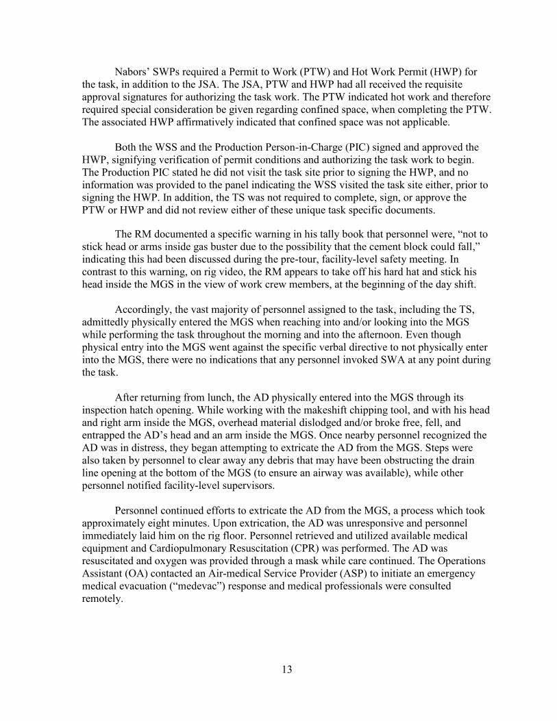


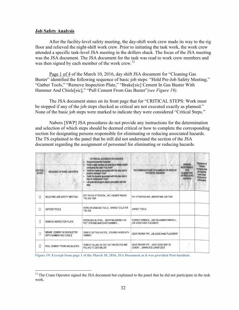


![Houma Ceres (Houma, Parish of Terrebonne, La.) 1857-01-03 [p ]chroniclingamerica.loc.gov/lccn/sn83026391/1857-01-03/ed-1/seq-4.pdf · Alo--MevaM•es, consisting of empty hgsheads,](https://static.documents.pub/doc/80x56/5c63a67709d3f26b1f8b8921/houma-ceres-houma-parish-of-terrebonne-la-1857-01-03-p-alo-mevames.jpg)


