48
INVESTIGATION OF PRESTRESSED BOX BEAM PLAZA STRUCTURES

INVESTIGATION OFPRESTRESSED BOX BEAM
PLAZA STRUCTURES

Michigan Department of TransportationMDOT
Investigation of Prestressed Box Beam Plaza StructuresZ01, Z02, and Z03 of 63102 over I-696 in Southfield, Michigan
Douglas E. Needham, P.E. Roger D. Till, P.E.
Testing and Research SectionConstruction and Technology Division
Research Project 98 TI-1892Research Report No. R-1391
Michigan Transportation CommissionBarton W. LaBelle, Chairman
Jack L. Gingrass, Vice-ChairmanBetty Jean Awrey, Ted B. Wahby,
Lowell B. Jackson, John W. GarsideGregory J. Rosine, Director
Lansing, February 2001

This report, authorized by the transportation director, has been prepared to provide technical information and guidancefor personnel in the Michigan Department of Transportation, the FHWA, and other reciprocating agencies. The cost ofpublishing 50 copies of this report at $3.87 per copy is $193.50 and it is printed in accordance with Executive Directive1991-6.

Technical Report Documentation Page1. Report No.
Research Report R-13912. Government Accession No. 3. Recipient’s Catalog No.
4. Title and Subtitle Investigation of Prestressed Box Beam PlazaStructures Z01, Z02, and Z03 of 63102 overI-696 in Southfield, Michigan
5. Report Date October, 2000
7. Author(s) Douglas E. Needham, P.E., Roger D. Till, P.E. 6. Performing Organization Code
9. Performing Organization Name and AddressMichigan Department of TransportationConstruction and Technology DivisionP.O. Box 30049Lansing, MI 48909
8. Performing Org Report No.
R-1391
12. Sponsoring Agency Name and AddressMichigan Department of TransportationConstruction and Technology DivisionP.O. Box 30049Lansing, MI 48909
10. Work Unit No. (TRAIS)
11. Contract/Grant No.
15. Supplementary Notes 13. Type of Report & Period Covered
14. Sponsoring Agency Code98 TI-1892
16. Abstract: This report investigates the plaza structures (Z01, Z02, and Z03 of 63102) that cross I-696 in Southfield,Michigan. These structures contained numerous diagonal shear cracks in the fascia as well as the interior beams after beingin service for 11 to 14 years. Reviewing the design files, we found that loads produced by a 10' tall concrete parapet wall werenot completely accounted for in the design of the fascia beams. Therefore, using AASHTO LRFD combined shear and torsionanalysis as well as analysis from Arthur H. Nilson, “Design of Prestressed Concrete,” we found that the fascia beams on allthree structures did not have sufficient vertical reinforcement to account for the loads imposed. However, when thesuperimposed dead loads were proportioned between the parapet wall and the fascia beam, only Z03 has sufficient verticalreinforcement when analyzed using the measured crack angle. We also found (assuming 5 feet of earth fill) that the east fasciabeams of span 1 and span 2 on Z01, the west fascia beams of span 1 and span 2 on Z02, 7 percent of the interior beams on Z01,and 42 percent of the interior beams on Z02 require additional longitudinal reinforcement at the bearing location to assist incontrolling diagonal shear cracks. During phase II of this investigation an extensive topographical survey on the top of all threestructures was performed and the maximum fill depths were located. These locations did not correlate with the cracked interiorbeams. Therefore, the interior beam cracks must have been initiated as a result of fabrication errors or during construction andgrown due to the lack of longitudinal reinforcement. Eight cost estimates were generated and from these it was decided toreplace the first four beams and parapet walls on all three structures as well as fifty-six interior beams on Z03 and place carbonfiber reinforced polymer (CFPR) sheets on the bottom flange of all remaining beams. As part of the repair contract, a total offive prestressed box beams were load tested and analyzed for material properties and reinforcement arrangements.
17. Key Words 18. Distribution StatementNo restrictions. This document is available to the publicthrough the Michigan Department of Transportation.
19. Security Classification (report)Unclassified
20. Security Classification (Page)Unclassified
21. No of Pages 22. Price
Form DOT F 1700.7 (8-72)
Acknowledgments
Although many people participated in this project, space and memory will not allow a complete listof everyone’s involvement. However, the following people should be mentioned: Dave Juntunen,Larry Pearson, Chris Davis, Ann Greenfield, Phil Tonkin, Mark Whipple, and Don Wotring of theConstruction and Technology Division; Paige Williams of the Maintenance Division; Brian Dolman-Jersey of the Design Division; the Geotechnical Unit; the Auburn Hills Garage Michigan Departmentof Transportation; Arnold Beller, Johnny Watkins, Larry Young of the Macomb TransportationService Center Michigan Department of Transportation; and the Angelo Iafrate ConstructionCompany.

TABLE OF CONTENTS
Executive Summary . . . . . . . . . . . . . . . . . . . . . . . . . . . . . . . . . . . . . . . . . . . . . . . . . . . . . . . . . . . 1
Introduction . . . . . . . . . . . . . . . . . . . . . . . . . . . . . . . . . . . . . . . . . . . . . . . . . . . . . . . . . . . . . . . . . . 5
Phase I . . . . . . . . . . . . . . . . . . . . . . . . . . . . . . . . . . . . . . . . . . . . . . . . . . . . . . . . . . . . . . . . . . . . . . 5Initial Field Inspection . . . . . . . . . . . . . . . . . . . . . . . . . . . . . . . . . . . . . . . . . . . . . . . . . . . . 5File Review . . . . . . . . . . . . . . . . . . . . . . . . . . . . . . . . . . . . . . . . . . . . . . . . . . . . . . . . . . . . 6Calculations . . . . . . . . . . . . . . . . . . . . . . . . . . . . . . . . . . . . . . . . . . . . . . . . . . . . . . . . . . . . 8
Phase II . . . . . . . . . . . . . . . . . . . . . . . . . . . . . . . . . . . . . . . . . . . . . . . . . . . . . . . . . . . . . . . . . . . . . 20
Summary . . . . . . . . . . . . . . . . . . . . . . . . . . . . . . . . . . . . . . . . . . . . . . . . . . . . . . . . . . . . . . . . . . . 25
References . . . . . . . . . . . . . . . . . . . . . . . . . . . . . . . . . . . . . . . . . . . . . . . . . . . . . . . . . . . . . . . . . . 29
Bibliography . . . . . . . . . . . . . . . . . . . . . . . . . . . . . . . . . . . . . . . . . . . . . . . . . . . . . . . . . . . . . . . . . 30
Figures . . . . . . . . . . . . . . . . . . . . . . . . . . . . . . . . . . . . . . . . . . . . . . . . . . . . . . . . . . . . . . . . . . . . . 31
Appendix A . . . . . . . . . . . . . . . . . . . . . . . . . . . . . . . . . . . . . . . . . . . . . . . . . . . . . . . . . . . . . . . . . 62Z01 of 63102 . . . . . . . . . . . . . . . . . . . . . . . . . . . . . . . . . . . . . . . . . . . . . . . . . . . . . . . . . . 63Z03 of 63102 . . . . . . . . . . . . . . . . . . . . . . . . . . . . . . . . . . . . . . . . . . . . . . . . . . . . . . . . . . 66Z03 of 63102 . . . . . . . . . . . . . . . . . . . . . . . . . . . . . . . . . . . . . . . . . . . . . . . . . . . . . . . . . . 69

1
EXECUTIVE SUMMARY
As a result of the visible fascia beam cracks in the plaza structures (Z01, Z02, and Z03 of 63102)over I-696 in Southfield, Michigan, the Maintenance Division asked the Structural Research Unit,Construction and Technology Division, to investigate the structural integrity of these structures. Toaccomplish this, we performed detailed field inspections, extensive file reviews (design data,construction history, and materials’ documentation), in-depth calculations, and extensive surveys.
Phase I
Through our inspections, we discovered that all three structures contained numerous diagonal cracksin the fascia beams as well as in the interior beams. Since the majority of the fascia beam crackswere outlined with either water or a leachate, they were visible from the roadway. A major sourceof water appeared to be the lawn sprinkler systems on top of each of the plaza structures.
Our file review revealed that the structures were built in the order of Z03, then Z01 and then Z02.Through this review, we discovered that the fascia beams on all three structures cracked either duringconstruction or soon after. In an attempt to alleviate the cracks, which appeared to have been causedby the placement of the 10-foot tall concrete parapet wall, the design methodology was modifiedafter the construction the first plaza structure. Unfortunately, the modification was not successful.During our review, we discovered that the parapet wall loads were not completely accounted for inthe design of the fascia beams on all three structures. We also did not find any mention noraccounting for the loads produced by the sidewalks, trees, playground equipment, or sprinklersystems that are present. These items appeared to have been placed after the design was completed.
Our analysis showed that the fascia and interior beams on all three structures should haveexperienced diagonal shear cracking during construction or soon after because the design shear loadswere greater than the shear strength of the concrete. However, a cracked beam does not necessarilymean that it is structurally deficient. If the steel stirrups and the concrete compression struts cancarry the excess load, then the beam is structurally sufficient.
For the fascia beams, the combined shear and torsional loading produced by the 10-foot tall concreteparapet wall was not completely accounted for in their design. Therefore, there was insufficientvertical reinforcing steel when the entire loads were used to analyze the beam(s). When thesuperimposed dead loads (snow and earth fill loading) were proportioned between the parapet walland the concrete beam(s), the fascia beams for Z01 and Z02 still had insufficient verticalreinforcement when analyzed using the measured crack angle obtained from our inspection. We alsodiscovered that the east fascia beams of span 1 and span 2 on Z01 and the west fascia beams of span1 and span 2 on Z02 had insufficient longitudinal tensile resistance at the bearing. As a result ofinsufficient longitudinal tensile resistance, once a shear crack develops, the longitudinal steel cannotprevent the crack from opening.

2
A total of twenty-three interior beams was analyzed for all three structures. Assuming 5 feet of earthfill, all twenty-three beams had sufficient vertical reinforcement steel and sufficient longitudinaltensile resistance at the critical shear location dv. However, from these analyzed beams we foundthat 7 percent of the interior beams on Z01 and 42 percent of the interior beams on Z02 hadinsufficient longitudinal tensile resistance at the bearing location, which allows shear cracks to openwider after the cracks have developed.
While reviewing the reinforcement details for the fascia beams, we found that neither thelongitudinal reinforcement nor vertical reinforcement (stirrups) is properly detailed for torsion. Forthe longitudinal reinforcement to be properly detailed it must be distributed around the perimeter ofthe closed stirrups. The majority of the longitudinal reinforcement for these structures consists ofthe prestressing strands, which are concentrated in the bottom flange. A properly detailed stirrupwould consist of one bar that wraps around the entire beam and is anchored with a 135-degree hookaround the longitudinal reinforcing steel. For each structure, the stirrups are lapped in the beam web.Fortunately, for all three structures, torsional loading on the fascia beams only comprises about 30percent of the load on the stirrups. Therefore, the beams are subjected to a greater shearing forcethan torsional force.
Aside from the reinforcing steel improperly detailed for torsion, the lap length for the welded wirefabric (WWF) shear reinforcement in Z03 was not properly detailed. The required lap length is 7-7/8inches, which is greater than the detailed lap length of 7 inches. To prevent premature failure of theWWF when used for transverse reinforcement, the wires must provide a minimum elongation of 4percent when measured over a 4-inch gage length and be stress relieved after fabrication accordingto AASHTO LRFD. Reviewing the specifications cited for WWF, we did not find elongationrequirements nor requirements for the WWF to be stress-relieved after fabrication. A lack of shearreinforcement lap length, along with the possibility of premature failure of WWF, may also explainthe diagonal shear cracks found on the interior beams of Z03. Since shear failures occurs with littlewarning, proper steel detailing is required to prevent premature failure.
At the end of Phase I, a list of possible solutions was generated to increase the durability and strengthof the beams to account for the added and unaccounted dead loads, i.e., additional earth fill,playground equipment, sidewalks, trees, and water from the sprinkler systems. From this list, it wasrecommended that the cracks in the fascia beams as well as any crack in the bottom flange of theinterior beams with a width greater than 0.010 inches be epoxy injected. It was also recommendedthat carbon fiber reinforced polymer (CFRP) sheets be attached to all of the exposed fascia beamwebs and all bottom flanges of the fascia beams. The CFRP sheets should also be attached to thebottom flanges of the first, second, and third interior beams from the east and west fascia for span1 and 2 on Z01 and Z02 and on the bottom flanges of any interior beam with a crack width(measured on the bottom flange) greater than 0.040 inches. In all cases, the CFRP should extend adistance not less than twice the beam depth from the end to provide the required shear and torsionalreinforcement. The CFRP sheets will also serve to mitigate the improper detailing of the torsionalreinforcement. The outside fascia beam web should be coated with a concrete coating in the areaof the CFRP sheets for esthetics. For the interior beams, the existing cracks in the webs should be
3
sealed to prevent moisture from contacting the reinforcing and prestressing steel by injecting anexpandable urethane foam between the beam gaps. The expandable urethane foam should extenda distance at least three times the beam depth from the end of the beam. Also, a topographical surveyof the earth fill should be performed. If the existing fill depths exceed the maximum fill depth asstated in Figures 16, 17, 18 (Z01, Z02, and Z03 summary of results, respectively), then the excessfill should be removed. Note that if the pine trees are removed along the parapet walls to reduce thetotal dead load applied to the fascia beams, then the affects of wind loading need to be consideredin the analysis. If removing the earth fill is not feasible, then attaching CFRP sheets to the bottomflanges for a distance not less than twice the beams depth from the end was recommended. On topof the structures, the sprinkler systems use should be eliminated. Maintenance should continue toinspect these structures on a six-month basis until the repair work is performed.
Phase II
Once Phase I was completed, a meeting was held with various Michigan Department ofTransportation (MDOT) personnel to discuss our findings from Phase I and to set the direction forPhase II. It was determined that the next logical step was to determine the maximum fill depths onall three structures. To ascertain the fill depths, we performed an extensive survey. From this, wefound that the current loads applied to the interior beams would not cause the magnitude and numberof cracks that were found. Therefore, the cracks must have been initiated during construction andgrown due to the lack of longitudinal reinforcement in the bottom flange. Through conversationswith the construction engineer at the time of construction, there were minimal load restrictionsplaced on the superstructure during the construction of Z03. However, as the successive bridgeswere built, the load restrictions increased. This was evidenced by the number of cracked beamsfound on the three structures. The first structure constructed, Z03, had the widest and largest numberof cracked beams and was constructed with minimal load restrictions. The second constructedstructure, Z01, had some load restrictions and had fewer and tighter cracks than Z03. The finalstructure constructed, Z02, had the most load restrictions and had minimal cracks on the interiorbeams.
Upon the completion of Phase II, there were a total of eight cost estimates generated. From the eightoptions investigated, it was decided to remove and replace the first four beams and parapet wall onall three structures as well as fifty-six interior beams on Z03 and place carbon fiber reinforcedpolymer (CFRP) sheets on the bottom flange of all remaining interior beams. The beam gaps of thecracked beams are also to be filled with urethane foam to prevent moisture from entering the beam.This option although the most expensive, $6,900,000, will provide the largest factor of safety andgreatly extend the service life of the plaza structures.
As part of the repair contract, the contractor was required to salvage and load test four of the replacedprestressed box beams to shear failure. The load test results were used to verify the adequacy of theremaining prestressed box beams. All of the box beams carried more than the expected load exceptfor beam number 166 (span 1) of Z03 of 63102. Upon removal of this beam we found an obviouscold joint and a layer of Styrofoam between the web and the bottom flange near the beam end. As

4
a result, the ultimate proof load at dv for this beam was less than the actual factored dead load plusfactored pedestrian loading at dv. Due to the obvious fabrication error, beam number 27 (span 2)from Z03 was salvaged, repaired according to the contract plans, and load tested. For beam number27, the ultimate proof load at dv was greater than the actual factored dead load plus factoredpedestrian loading at dv. The remainder of the tested beams demonstrated that the remaining beamshave adequate shear strength to carry the applied loads.

5
INTRODUCTION
In October 1996, a motorist wrote a letter to the MDOT with concerns regarding the visible cracksin the fascia beams of the plaza structures that cross I-696 in Southfield, Michigan, Z01, Z02, andZ03 of 63102. Soon after the department received the letter, the Structural Research Unit, along withthe Bridge Maintenance Unit, performed an initial investigation to determine the validity of themotorist’s concern. From this, we determined that the condition of these three structures requiredfurther investigation. Therefore, under request by the Maintenance Division, the StructuralResearch Unit opened a technical investigation to determine cause of the cracks and the structuralintegrity of these structures.
These plaza structures serve as recreational parks and were created for the local community in thelate 1980s. The first structure in service, Z03, was constructed in 1985 and followed by Z01 thenZ02, both in 1988. All three contain a 10-foot tall concrete parapet wall located on the top edge ofthe fascia beams, which creates a combined shear and torsional loading, and about 5 feet of earth fillcovering the top of the structures. In addition, they also contain playground equipment, sidewalks,sprinkler systems, roadway (Z03 only), and numerous trees. During the investigation, we performeddetailed field inspections, extensive file reviews (design data, construction history, and materialsdocumentation), in-depth calculations, and extensive surveys.
PHASE I
Initial Field Inspection
The first step in our technical investigation was to perform a detailed inspection on all threestructures. During these inspections, in May and June of 1998, we closed the fast lane of traffic andconcentrated on the pier end of the beams. Any comments about the abutment ends were madebased on viewing from the pier. Our efforts were concentrated on the first three interior box beamsfor Z03 and the first four box beams for Z01 and Z02. The difference in our concentration was dueto the different designs, i.e., how the parapet wall forces are carried. For Z03, the fascia beamcarried the entire weight of the earth fill and parapet wall. The second interior beam resisted theearth pressure torsional forces through a turnbuckle assembly that was attached to the parapet walland the second interior beam, refer to Figure 1. For Z01 and Z02, the parapet wall forces,superimposed dead loads and torsional loads, were distributed through the first four beams that weretransversely post-tensioned together at four locations along the span length, refer to Figure 2.
Through our inspections, we discovered that all three structures contained beams with numerousdiagonal cracking at the beam ends. The amount and size of the cracks appeared to be less on Z03when compared with the other two structures, refer to Figures 3 through 14. Also, the interior beamsof Z01 and Z03 contained many beams with diagonal shear cracks. In one location on Z03, a bottomflange crack measured wider than 0.060 inches. The inspection on top of the structure revealedsprinkler systems, numerous trees, playground equipment, sidewalks, roadway (Z03 only), and earthfill greater than 4 feet. Only 4 feet of earth fill was detailed in the original contract plans. During

6
our inspection of Z01 and Z02, we extracted part of the wet earth fill and brought it back to thelaboratory for analysis. From these samples we learned that the clayey sand fill had a naturalmoisture content of 17.6 and 22.6 percent, for Z01 and Z02 respectively. Through a visualinspection performed by Dan Troia (MDOT Soils Engineer), it was suggested that the unit weightof the soil was closer to 140 pcf rather than the 120 pcf stated in the design notes. Refer to AppendixA for the detailed inspection reports.
During our inspection, we also discovered that most of the weep holes in the inspected beams stillhad the plastic cap in tact. With concern of water being retained in the beam cavity, we attemptedto remove the caps. As we removed the plastic caps, water drained from a couple of the beams.Since most of the cracks on the fascia beams were outlined with leachate and/or water at the timeof our inspection, it was not surprising to discover that water was entering the beam cavity.
As a result of finding the plastic caps still in tact and moisture collecting in a couple of the inspectedbeams, the Auburn Hills Special Crew, MDOT, was asked to probe the weep holes in every beamon all three structures. We were concerned with moisture collecting in the interior beams andsubstantially increasing the applied load. During this operation, the Auburn Hills Special Crewunplugged numerous weep holes that had the plastic cap still in tact but never found standing water.However, some of the beams did not have weep holes as specified in the plans. For these beams,we did not attempt to create a weep hole due to concern with damaging the prestressing strands.Therefore, even though standing water was not found in the beams that had the weep holesunplugged, we can now confidently state that if and when moisture collects in the interior of thesebeams it will have a path to drain. However, for the beams without weep holes, there is still existsa concern with moisture collecting.
File Review
After our detailed inspections, an extensive file review was performed. Construction history, designdata, and the material documentation files were reviewed. The twenty-six boxes of constructionhistory for job numbers 21960, 21961, and 21858 were requested for Z01, Z02 and Z03 of 63102,respectively. From these files, we were able to determine that problems with the plaza structuresappeared either during construction or soon there after. Problems with the fascia beams on Z03initiated with the placement of the 10-foot tall concrete barrier wall. As the west parapet wall waspoured, the west fascia beams cracked. Although this was noticed, the placement of the concretecontinued. Due to this problem with Z03, the design of Z01 and Z02 was modified in an attempt toprevent the cracks from occurring. The first four box beams were transversely post-tensioned at fourlocations along the span, unlike Z03 that had two tie rods placed transversely along the span.However, modifying the design did not stop the formation of cracks. Soon after the placement ofthe parapet wall, cracks formed in both of the east fascia beams of Z01. With concern about crackgrowth, the Structural Research Unit was asked to instrument and monitor the cracks for anychanges. The cracks in Z01 fascia beams were monitored from July 1989 through March 1991during which time it was found that the cracks were stable and epoxy injection of the cracks wasrecommended. Since the design modification for Z01 failed to produce a crack free fascia beam,

7
further modifications for Z02 were designated. Light weight fill was to be used around the parapetwall to reduce the dead load. Through our field inspection, we found this not to be the case. Thefill material found on the Z02 structure was the same as the other two structures. Therefore, as withZ01, soon after constructing the parapet wall, cracks developed on the Z02 fascia beams. Thesecracks were not monitored.
The eleven folders of design files revealed that all three structures were designed using MDOT’sStandard Bridge Design Computer Program (MDOT Bridge Program). The applied dead loads were4 feet of 120 pcf of earth fill, 1 foot of 40 pcf of snow, and a future wearing surface at 25 psf. Thedead load created by the 10-feet high concrete parapet wall was not included in the computer designcalculations. Instead, a hand calculation was performed to verify that the beam had sufficientflexural strength to carry the parapet wall. From this it was found that the beam was sufficient inflexure. However, the effects of shear were never considered. Also, nowhere in the design fileswere sidewalks, trees, playground equipment, nor water from the sprinkler systems noted.Additionally, there was no mention nor accounting for the combined shear and torsional loadsproduced by the concrete parapet wall. As a result, this left some questions that could only beanswered through in-depth calculations. One item that we found in the design files was a partial setof shop drawings for Z03, which indicated welded wire fabric was substituted for the reinforcingbars shown on the contract plans. Through all of our searching, this was the only set of shopdrawings for any of the three structures that we were able to locate in the department’s files. Since we were unable to locate all of the shop drawings, we searched the Construction andTechnology’s microfilm files for material information that might be of use. We were unable to findany information about Z03 of 63102 in the files. In an attempt to locate the microfilm for jobnumber 21858 (Z03), we searched microfilm roll numbers 1893 through 1960 and were unable tolocate any records corresponding to Z03. The project was finalized in 1990, so the records shouldhave been microfilmed in 1990 or 1991. The files covering this time period are in rolls 1909 to1925. Although we were unable to find files on Z03, we were able to locate the materialdocumentation files for Z01 and Z02. As a result, we were able to modify the yield strength of thestirrups and verify the prestressed concrete strength for Z01. During our search for the stirrupstrength of Z02, we discovered that welded wire fabric (WWF) was used for the construction of theprestressed box beams. This differed from the As Constructed Plans. Personal communication withMr. Bob Livesay (MDOT shop inspector at the time) confirmed that WWF was used. As with Z01,we were able to verify the prestressed concrete strength for Z02.
Due to our unsuccessful search in finding the shop drawings in MDOT’s record center, we contactedMr. Jim Clapper. Mr. Clapper worked for Superior Products Company, who made the beams, at thetime of the fabrication. Mr. Clapper stated that last he knew the files for Z02 and Z03 were in thebasement of Cole Pipe. Cole Pipe bought Superior Products Company some time after thecompletion of the plaza structures. Therefore, in June 1998, Mr. Randy Anteau at Cole Pipe wascontacted for possible use of their structure files. Mr. Anteau indicated that the old files that werestored in the basement were destroyed in May 1998. On a positive note, on October 20, 1998, Mr.Paul Malloure of C.A. Hull Co., Inc. sent us a copy of the shop drawings for Z01 of 63102, which

8
indicated 9/16-inch diameter prestressing strands were substituted for the ½-inch diameter strandsshown on the contract plans.
Calculations
After the inspection and file review were performed, the next step was to analyze the structures anddetermine if they were structurally adequate to carry the existing loads. For the analysis, wereferenced both American Association of State Highway and Transportation Officials LRFD BridgeDesign Specifications (AASHTO LRFD) 1998 and Arthur H. Nilson, Design of PrestressedConcrete, 1978 (Nilson). AASHTO LRFD was used as the primary code for analysis with Nilsonused as a check. For both analyzes, factored loads were used. For the Nilson analysis the loads werefactored according to AASHTO Standard Specifications for Highway Bridges (AASHTO Standard)1996 and compared with the ultimate strength using capacity reduction factors from AASHTOStandard and/or American Concrete Institute Building Code Requirements for Structural Concrete318-95 (ACI). Our analysis differed from the original design methodology because during theoriginal design of the plaza structures in the 1980's, neither AASHTO Standard nor ACI addresseddesign of prestressed concrete beams for combined shear and torsion.
For our analysis of the fascia beams we used 5 feet of earth fill at 140 pcf, 1 foot of snow at 40 pcf,10-foot tall concrete parapet wall, and the self weight of the box beam(s). A further refinement ofour analysis included a temperature loading to account for all supports being fixed against thermalmovement. The earth fill of 5 feet at 140 pcf was used to match the current field conditions. Thisdepth differs from the maximum depths as shown on the plans. The contract plan sheets show thateach structure has a different design earth fill depth. The design loading for Z01 was the greater ofeither 3 feet 6-inches of earth fill or HS20 plus 2 feet 3 inches of earth fill. For Z02 the designloading was the greater of either 3 feet 9 inches of earth fill or HS20 plus 2 feet 9 inches of earth filland the design loading for Z03 was the greater of either 4 feet 0 inches of earth fill or HS20 loadingplus 2 feet 9 inches of earth fill. The unit weight of the designed earth fill was 120 pcf. For ouranalysis, we focused on the earth fill option and not the live loads because after inspecting thestructures we found only one structure, Z03, that allows only cars. Truck traffic is restricted.Therefore, we concentrated our analysis on the average fill depth of 5 feet as determined though ourinspection. Reviewing the MDOT Bridge Program input verification sheets for the prestressed boxbeams, we found that 1 foot of snow load at 40 pcf and a future wearing surface at 25 psf were alsoaccounted for in the applied design loads. The shear load produced by the 10-foot tall concreteparapet wall was not completely accounted for in the design of the fascia beams on all threestructures.
Wind loading on the exposed face of the parapet wall (about 5 feet) had been omitted in the designand analysis. Even though wind loading is included in the AASHTO load cases, we omitted itsaffect due to the proximity of pine trees that line the parapet walls. When the wind loads are appliedto the exterior face of the parapet wall, the torsional loading produced by the dead load weight of theparapet wall is reduced. When the wind blows across the interior portion of the plaza structures, itis diffused by the pine trees, playground equipment, and mounds of earth fill that are present on all

9
three structures. However, if the pine trees are removed along the parapet walls to reduce the totaldead load applied to the fascia beams, then the affects of wind loading need to be considered in theanalysis.
For the fascia beams analyzed, the factored loads, using 5 feet of earth fill at 140 pcf, 1 foot of snowload at 40 pcf, 10-foot tall concrete parapet wall, and the self weight of the beam(s), are greater thanboth the shear strength of the concrete and the nominal design strength of the fascia beam(s) whenthe beams are assumed to carry 100 percent of the superimposed dead load. Since the shear strengthof the concrete was exceeded, diagonal shear cracking was expected on all of the fascia beams onZ01, Z02, and Z03. Keep in mind that a cracked beam does not mean that it is structurallyinsufficient. If the steel stirrups and the concrete compression struts can carry the excess load, thenthe beam is structurally sufficient.
In addition to the nominal design strength of the fascia beam(s) being exceeded, the stirrups werenot detailed appropriately for torsion. For each structure, the stirrup lap of the top and bottom bars(or WWF) occurred in the beam webs. A properly detailed stirrup for torsion consists of one barwrapped around the entire beam and anchored to the longitudinal reinforcing steel with a 135-degreehook. This detail is preferred because when a rectangular beam fails in torsion, the corners of thebeam tend to spall off due to the inclined compressive forces. If the stirrups are not properlyanchored when the concrete spalls, the reinforcing steel will not provide the required resistance.Fortunately, for the three plaza structures, only about 30 percent of the load on the stirrups isrequired for torsion in the fascia beams. Therefore, the beams are subjected to a greater shearingforce than torsional force. However, if any slip occurs in the stirrups as a result of an improper detailfor torsion, this could be detrimental to the shear strength of the beams.
Also, the lap length for the WWF shear reinforcement for Z03 was not properly detailed. At thebeam ends the required lap length is 7-7/8 inches compared the detailed lap of only 7 inches.Therefore, the web shear forces may not be properly restrained. This improper lap length could leadto premature slipping of the stirrups.
According to AASHTO LRFD, if WWF, with wires located perpendicular to the axis of the member,is used for transverse reinforcement, the transverse wires must have a minimum elongation of 4percent measured over a 4-inch gage length including at least one cross wire. Reviewing ASTMA185 and A82, the specifications cited for WWF, we did not find any elongation requirements.Therefore, this criterion, although not required during the original design, was not checked. If theWWF cannot meet the elongation requirements and if the WWF was not stress relieved afterfabrication, it may fail before the required strain is obtained.
Throughout the analysis, the tensile requirements of the longitudinal reinforcement were determined.It should be mentioned that the longitudinal reinforcement must be distributed around the perimeterof the closed stirrups for proper placement regarding torsion. For these structures, the majority ofthe longitudinal resistance is provided by the prestressing strands, which are concentrated in the
10
bottom flange. For Z02 and Z03, which use WWF, the small amount of longitudinal reinforcementdoes not provide a significant amount of resistance.
Z01 of 63102
The first structure analyzed, Z01, was the only one of the three structures constructed with Grade 40#4 bar stirrup cages. With the cooperation of C.A. Hull Co., Inc. we obtained a copy of the shopdrawings. From these drawings, we determined that the stirrups were similar to that detailed in thecontract plans. However, the prestressing strands were increased from a ½-inch diameter as statedin the contract plans to 9/16-inch diameter, along with a corresponding decrease in the number ofstrands. Through our file review, we found beams designed with both ½-inch and 9/16-inchdiameter prestressing strands. For determining the prestressing forces, we used the initial prestressforce per shop drawings and total losses determined through the MDOT Bridge Program. Also, byreviewing the mill certifications, we were able to modify the yield strength of the stirrups to 45 ksiusing a statistical method based on the final draft of the Canadian Bridge Design Code.
Three different fascia beams (Beams P1-1, P5-24, and P10-24 as designated on the plans), along withten interior beams, were analyzed to determine if they are adequate to carry the existing loads. Thesebeams represented the maximum span length for the beam depth and prestressing strandcombination.
Beam P1-1
The first beam, P1-1, was the west fascia beam of span 1. This 48-inch box beam, had a center ofbearing to center of bearing span length of 86'-6inch and a total of thirty-four prestressing strandswith twenty-two bonded at the beam end. Since the first four box beams were post-tensionedtogether, we had to first determine if the four beam combination acted as a unit. This was performedby determining the torsional shear force present between the beams and comparing it with thefrictional force created by the transverse post-tensioning. Using the applied loads, it was found thatthe frictional force was adequate to carry the torsional shear force. Once we found that the beamcombination acts as a unit, a model of the beams was generated in a finite element program,GTSTRUDL, and the proportion of the applied loads carried by the fascia beam was determined.From the finite element program, we discovered that the fascia beam carried 23 percent of the earthand snow load located above the box beam combination and 80 percent of the parapet wall. Weexpected a large percentage of the parapet weight to be carried by the fascia beam because there wasnot enough area between the parapet wall and fascia beam to evenly distribute the load to the fourbeam combination.
Once the distribution factors of the applied loads were determined, the next step was to check if thereinforcing steel in the exterior fascia beam web was sufficient to carry the loads. The exterior webof the fascia beam was analyzed because at this location the shear and torsional forces are additive.During our analysis, we checked the beam for combined shear and torsion according to designprocedures in the AASHTO LRFD as well as analyzed the beam with the measured crack angles that

11
were obtained though our field inspection. AASHTO LRFD addresses combined shear and torsionsection using the modified compression theory, which accounts for the contribution of tensilestresses in the concrete between cracks. Therefore, the crack angle plays an important role in thedesign and/or analysis. Since the design angle differed from the measured angle, we performed twodifferent analyses. Therefore, using the combined shear and torsional design per AASHTO LRFD,we found that for Grade 45 (modified per the final draft of Canadian Bridge Design Code) stirrups,the box beam combination requires 0.21 in2 of steel per 7-inch stirrup spacing for the vertical steelper design. Per analysis, the exterior fascia web requires 0.28 in2 of steel per 7-inch stirrup spacing.Both requirements exceeded the existing stirrup reinforcement steel of 0.20 in2 of steel per 7-inchstirrup spacing. Since the required reinforcement was greater than the existing reinforcement, weperformed further analysis to determine if the 10-foot tall concrete parapet wall would act compositewith the four beam combination and take part of the superimposed dead load (earth fill and snowloads). Using the interface shear transfer - shear friction theory from AASHTO LRFD, we foundthat the parapet wall did act composite with the four beam combination and could take a portion ofthe superimposed dead load. Our next step was then to determine the amount of superimposed deadload that the wall carried. For this, we proportioned the superimposed dead between the parapet walland four beam combination using relative stiffness and the effective moment of inertia. After threeiterations using the effective moment of inertia, we found that the parapet wall can take about 42percent of the superimposed dead load. It should be noted that the parapet wall did not have enoughflexural capacity to withstand the imposed superimposed dead load but would show signs of distresswhen overloaded that would alert inspectors to take corrective action. Subtracting the portion of thesuperimposed dead load carried by the parapet wall and applying the distribution factor of 23 percentobtained from finite element analysis, we found that 0.11 in2 of steel per 7-inch stirrup spacing wasrequired for the design of the exterior web of the fascia beam web and that 0.22 in2 of steel per 7-inch stirrup spacing was required per analysis. Although the design requirement was less than theexisting 0.20 in2 of steel per 7-inch stirrup spacing, the required reinforcing steel per analysis usingmeasured crack angles was insufficient.
Using the measured crack angle and the proportioned superimposed dead loads, we found that thelongitudinal tensile resistance provided at the critical section dv and at the bearing was sufficient toovercome the respective longitudinal tensile forces.
As stated, two different methods were performed during the analysis of these beams. For theanalysis method according to Nilson, the total load applied was divided evenly between the four boxbeams; i.e., the parapet wall was distributed evenly to the four beams. From this analysis, we foundthat prior to proportioning the superimposed dead load between the box beam combination andparapet wall, the exterior web of the fascia beam required 0.27 in2 of steel per 7-inch stirrup spacing.After proportioning the superimposed dead load, the exterior web of the fascia beam required 0.17in2 of steel per 7-inch stirrup spacing.
Using AASHTO LFRD and the measured crack angles, we determined that the maximum earth fillbased on the existing longitudinal steel resistance at the bearing (controlling case) along with theexisting stirrups. When the entire superimposed dead load was considered, the maximum fill based

12
on the longitudinal steel resistance was 3.5 feet and the maximum fill based on the existing stirrupswas 3.7 feet. Proportioning the superimposed dead load between the parapet wall and the box beamcombination, the maximum fill based on the longitudinal resistance was 6.2 feet and the maximumfill based on the existing stirrups was 6.6 feet.
A summary of analysis for Beam P1-1 is shown in Figure 15.
Beam P5-24
The second beam analyzed for Z01 of 63102, P5-24, was the east fascia beam of span 1. This 60-inch box beam had a center of bearing to center of bearing span length of 97 feet 9-3/4 inches anda total of thirty-four prestressing strands with twenty-two bonded at the beam end. Using the samemethods as beam P1-1, we found that the transverse post-tensioning force provided sufficientfrictional force to overcome the torsional shear force presented with the applied loads. Through afinite element analysis of the four beam combination, we found the fascia beam carried 23 percentof the earth and snow loading, and 80 percent of the parapet wall loading.
Using the distribution factors obtained through finite element analysis and AASHTO LRFDcombined shear and torsion specifications, we found for design, the exterior fascia beam webrequired 0.24 in2 of steel per 9-inch stirrup spacing and for analysis using measured crack angles theexterior fascia beam web required 0.33 in2 of steel per 9-inch stirrup spacing. Both requirementsexceeded the existing stirrup reinforcement steel of 0.20 in2 of steel per 9-inch stirrup spacing. Sincethe required reinforcement was greater than the existing reinforcement, we proportioned thesuperimposed dead loads between the parapet wall and the four beam combination as previouslystated. From this, we found that the parapet wall could take about 30 percent of the superimposeddead load. Subtracting this from the total superimposed dead load and applying the distributionfactor of 23 percent obtained from finite element analysis, we found that 0.15 in2 of steel per 9-inchstirrup spacing was required for design and 0.28 in2 of steel per 9-inch stirrup spacing was requiredper analysis. Although the design requirement was less than the existing 0.20 in2 of steel per 9-inchstirrup spacing, the required reinforcement steel per analysis using measured crack angles wasinsufficient.
As with the previous beam, by using the measured crack angle and the proportioned superimposeddead loads, we found that the longitudinal tensile resistance provided at the critical section dv wassufficient to overcome the longitudinal tensile forces at this location. However, at the bearinglocation, the longitudinal tensile resistance was not sufficient to restrain the longitudinal tensileforces. As a result of the insufficient longitudinal tensile resistance, once a shear crack develops,the longitudinal steel could not prevent the crack from opening.
Analyzing the fascia beam according to Nilson and distributing the total applied loads evenlybetween the four beam combination, we found that the exterior fascia beam web required 0.28 in2
of steel per 9-inch stirrup spacing. When the superimposed dead load was proportioned between the

13
parapet wall and four beam combination, the exterior fascia beam web required 0.20 in2 of steel per9-inch stirrup spacing.
Using AASHTO LFRD and the measured crack angles, we determined that the maximum earth fillbased on the existing longitudinal steel resistance at the bearing (controlling case) along with theexisting stirrups. When the entire superimposed dead load was considered, the maximum fill basedon the longitudinal steel resistance was 1.9 feet and the maximum fill based on the existing stirrupswas 2.9 feet. Proportioning the superimposed dead load between the parapet wall and the box beamcombination, the maximum fill based on the longitudinal resistance was 2.8 feet and the maximumfill based on the existing stirrups was 4.2 feet.
A summary of analysis for Beam P5-24 is shown in Figure 15.
Beam P10-24
The third and final beam for Z01 of 63102, P10-24, was the east fascia beam of span 2. This 60-inchbox beam, had a center of bearing to center of bearing span length of 113'-3 5/8-inch and total offorty-two of prestressing strands with twenty-four bonded at the beam end. Using the same methodsas previously discussed, we found that the transverse post-tensioning force provided sufficientfrictional force to overcome the torsional shear force presented with the applied loads. Through afinite element analysis of the four beam combination, we found the fascia beam carried 23 percentof the earth and snow loading, and 79 percent of the parapet wall loading. Using the distribution factors obtained through finite element analysis and AASHTO LRFDcombined shear and torsion specifications, we found for design the exterior fascia beam webrequired 0.28 in2 of steel per 7-inch stirrup spacing and for analysis of the box beam using measuredcrack angles the exterior fascia beam web required 0.32 in2 of steel per 7-inch stirrup spacing. Bothrequirements exceeded the existing stirrup reinforcement steel of 0.20 in2 per 7-inch stirrup spacing.Therefore, we proportioned the superimposed dead loads between the parapet wall and the four beamcombination. From this, we found that the parapet wall could take about 29 percent of thesuperimposed dead load. Subtracting this from the superimposed dead load and applying thedistribution factor of 23 percent obtained from finite element analysis, we found that 0.19 in2 of steelper 7-inch stirrup spacing was required for design and 0.27 in2 of steel per 7-inch stirrup spacing wasrequired per analysis. Although the design requirement was less than the existing 0.20 in2 of steelper 7-inch stirrup spacing, the required reinforcement steel per analysis using measured crack angleswas insufficient. As with the previous beams, by using the measured crack angle and the proportioned superimposeddead loads, we found that the longitudinal tensile resistance provided at the critical section dv wassufficient to overcome the longitudinal tensile forces at this location. However, at the bearinglocation, the longitudinal tensile resistance was not sufficient to restrain the longitudinal tensileforces. As a result of the insufficient longitudinal tensile resistance, once a shear crack develops,the longitudinal steel could not prevent the crack from opening.

14
Analyzing the fascia beam according to Nilson and distributing the total applied loads evenlybetween the four beam combination, we found that the exterior fascia beam web required 0.31 in2
of steel per 7-inch stirrup spacing. When the superimposed dead load was proportioned between theparapet wall and four beam combination, the exterior fascia beam web required 0.22 in2 of steel per7-inch stirrup spacing.
Using AASHTO LFRD and the measured crack angles, we determined that the maximum earth fillbased on the existing longitudinal steel resistance at the bearing (controlling case) along with theexisting stirrups. When the entire superimposed dead load was considered, the maximum fill basedon the longitudinal steel resistance was 1.6 feet and the maximum fill based on the existing stirrupswas 2.9 feet. Proportioning the superimposed dead load between the parapet wall and the box beamcombination, the maximum fill based on the longitudinal resistance was 2.3 feet and the maximumfill based on the existing stirrups was 4.2 feet.
A summary of analysis for Beam P10-24 is shown in Figure 15.
Interior Beams
Ten different interior beam sizes were checked for adequate shear strength. The sizes and spansranged from a 48-inch box beam with a center of bearing to center of bearing span of 89 feet 6 inchesto a 60-inch box beam with a center of bearing to center of bearing span of 112 feet 0 inches. Forall ten beams, the required vertical reinforcement, longitudinal tensile resistance at the criticalsection dv, and the longitudinal tensile resistance at the bearings were determined. In each case, therequired vertical reinforcement was less than the existing vertical reinforcement and the longitudinaltensile resistance provided at the critical section dv was sufficient to overcome the respectivelongitudinal tensile forces. However, one out of the ten beams, which represents roughly 7 percentof the total number of interior beams, had inadequate longitudinal tensile resistance at the bearing.For the interior beams, we determined the maximum earth fill based on the existing longitudinal steelresistance at the bearing, which was the controlling case. From this we found that the maximum fillfor a 48-inch box beam should be 5.9 feet, for a 54-inch box beam the maximum fill should be 5.3feet, and for a 60-inch box beam the maximum fill should be 4.7 feet.
Refer to Figure 16 for the analysis results of the ten interior beams.
Z02 of 63102
As with Z01, Z02 also utilizes the transverse post-tensioning of the first four box beams. Therefore,the same theory and methodology for analysis were used for both Z01 and Z02. However, throughour file review, we found that the prestressed box beams for Z02 were constructed with Grade 60WWF in lieu of the Grade 40 #4 bar stirrups as detailed in the contract plans. Since we were unableto determine the location and spacing of the WWF without shop drawings, we could not evaluatethe beams as constructed. However, assuming the WWF provided the same resistance as the #4 barstirrups, the box beams were evaluated per the contract plans.

15
Beam P14-22
The first beam analyzed, P14-22, was the east fascia of span 2. This 48-inch box beam, had a centerof bearing to center of bearing span length of 88 feet 8inches and total of forty-two of prestressingstrands with twenty-four bonded at the beam end. Using the same theory as discussed for Z01 of63102, we found that the transverse post-tensioning force provided sufficient frictional force toovercome the torsional shear force presented with the applied loads. Through a finite elementanalysis of the four beam combination, we found the fascia beam carried 23 percent of the earth andsnow loading, and 80 percent of the parapet wall loading.
Using the distribution factors obtained through finite element analysis and AASHTO LRFDcombined shear and torsion specifications, we found that for design the exterior fascia beam webrequired 0.22 in2 of steel per 6-inch stirrup spacing and for analysis the exterior fascia beam webrequired 0.35 in2 of steel per 6-inch stirrup spacing. Both requirements exceed the existing stirrupreinforcement steel of 0.20 in2 of steel per 6-inch stirrup spacing. Therefore, we proportioned thesuperimposed dead loads between the parapet wall and the four beam combination. From this, wefound that the parapet wall could take about 42 percent of the superimposed dead load. Subtractingthis from the total superimposed dead load and applying the distribution factor of 23 percentobtained from finite element analysis, we found that 0.13 in2 of steel per 6-inch stirrup spacing wasrequired for design and 0.27 in2 of steel per 6-inch stirrup spacing was required per analysis.Although the design requirement was less than the existing 0.20 in2 of steel per 6-inch spacing, therequired reinforcement steel per analysis using measured crack angles was insufficient.
As with the previous beams for Z01 of 63102, by using the measured crack angle and theproportioned superimposed dead loads, we found that the longitudinal tensile resistance providedat the critical section dv and at the bearing was sufficient to overcome the respective longitudinaltensile forces.
Analyzing the fascia beam according to Nilson and distributing the total applied loads evenlybetween the four beam combination, we found that the exterior fascia beam web required 0.29 in2
of steel per 6-inch stirrup spacing. When the superimposed dead load was proportioned between theparapet wall and four beam combination, the exterior fascia beam web required 0.19 in2 of steel per6-inch stirrup spacing.
Using AASHTO LFRD and the measured crack angles, we determined that the maximum earth fillbased on the existing longitudinal steel resistance at the bearing (controlling case) along with theexisting stirrups. When the entire superimposed dead load was considered, the maximum fill basedon the longitudinal steel resistance was 2.8 feet and the maximum fill based on the existing stirrupswas 2.1 feet. Proportioning the superimposed dead load between the parapet wall and the box beamcombination, the maximum fill based on the longitudinal resistance was 5.0 feet and the maximumfill based on the existing stirrups was 3.9 feet.
A summary of analysis for Beam P14-22 is shown in Figure 15.

16
Beam P8-1
The final beam analyzed for Z02 of 63102, P8-1, was the west fascia of span 2. This 60-inch boxbeam had a center of bearing to center of bearing span length of 111 feet 9-3/8 inches and a total offifty-four of prestressing strands with twenty-four bonded at the beam end. Since this beamcombination was similar to that of P10-24 of Z01 of 63102, we used a portion of the analysisobtained from P10-24 for P8-1. The only difference between the two beams as detailed in theMDOT plans was that the center of bearing to center of bearing span length for P10-24 was 113 feet3-5/8 inches and the center of bearing to center of bearing for P8-1 was 111 feet 9-3/8 inches.Therefore, the shear and torsional forces will be slightly less for Z02, however, the minor differencewill not significantly affect the outcome. The previous results for P10-24 of Z01 could not be usedto directly compare P8-1 of Z02 because the prestressing strands used for Z01 were 9/16-inchdiameter and for Z02 they were ½-inch diameter. However, by using P10-24 of Z01 of 63102, wefound that the transverse post-tensioning force provided sufficient frictional force to overcome thetorsional shear force presented with the applied loads and through a finite element analysis of thefour beam combination, we found the fascia beam carried 23 percent of the earth and snow loadingand 79 percent of the parapet wall loading.
Using the distribution factors obtained through finite element analysis and AASHTO LRFDcombined shear and torsion specifications, we found that for design the exterior fascia beam webrequired 0.38 in2 of steel per 6-inch stirrup spacing and for analysis the exterior fascia web required0.34 in2 of steel per 6-inch stirrup spacing. Both requirements exceed the existing stirrupreinforcement steel of 0.20 in2 of steel per 6-inch stirrup spacing. Therefore, we proportioned thesuperimposed dead loads between the parapet wall and the four beam combination. From this, wefound that the parapet wall could take about 29 percent of the superimposed dead load. Subtractingthis from the total superimposed dead load and applying the distribution factor of 23 percentobtained from finite element analysis, we found that 0.25 in2 of steel per 6-inch stirrup spacing wasrequired for design and 0.29 in2 of steel per 6-inch stirrup spacing was required per analysis usingmeasured crack angles. Therefore, if the WWF substituted for the #4 bar stirrups provided anequivalent resistance per 6-inch, then the required vertical reinforcing steel exceeded the existingreinforcement.
By using the measured crack angle and the proportioned superimposed dead loads, we found that thelongitudinal tensile resistance provided at the critical section dv was sufficient to overcome thelongitudinal tensile forces at this location. However, at the bearing location, the longitudinal tensileresistance was not sufficient to restrain the longitudinal tensile forces. As a result of the insufficientlongitudinal tensile resistance, once a shear crack develops, the longitudinal steel could not preventthe crack from opening.
Analyzing the fascia beam according to Nilson and distributing the total applied loads evenlybetween the four beam combination, we found that the exterior fascia beam web required 0.34 in2
of steel per 6-inch stirrup spacing. When the superimposed dead load was proportioned between the

17
parapet wall and four beam combination, the exterior fascia beam web required 0.26 in2 of steel per6-inch stirrup spacing.
Using AASHTO LFRD and the measured crack angles, we determined that the maximum earth fillbased on the existing longitudinal steel resistance at the bearing (controlling case) along with theexisting stirrups. When the entire superimposed dead load was considered, the maximum fill basedon the longitudinal steel resistance was 1.1 feet and the maximum fill based on the existing stirrupswas 2.3 feet. Proportioning the superimposed dead load between the parapet wall and the box beamcombination, the maximum fill based on the longitudinal resistance was 1.7 feet and the maximumfill based on the existing stirrups was 3.1 feet.
A summary of analysis for Beam P8-1 is shown in Figure 15.
Interior Beams
Twelve different interior beam sizes were checked for adequate shear strength. The sizes and spansranged from a 48-inch box beam with a center of bearing to center of bearing span of 89 feet 6 inchesto a 60-inch box beam with a center of bearing to center of bearing span of 111 feet 0 inches. Forall twelve beams the required vertical reinforcement, longitudinal tensile resistance at the criticalsection dv, and the longitudinal tensile resistance at the bearings were determined. In each case, therequired vertical reinforcement was less than the existing vertical reinforcement and the longitudinaltensile force at the critical section dv was less than the longitudinal tensile resistance at dv. However,eight of the twelve beams, which represents about 42 percent of the total interior beams, hadinsufficient longitudinal tensile resistance at the bearing. The lack of longitudinal tensile resistancemay explain why we saw large crack widths on the interior beams.
For the interior beams, we determined the maximum earth fill based on the existing longitudinal steelresistance at the bearing, which was the controlling case. From this we found that the maximum fillfor a 48-inch box beam should be 6.3 feet, for a 54-inch box beam the maximum fill should be 4.5feet, and for a 60-inch box beam the maximum fill should be 3.5 feet.
Refer to Figure 17 for the analysis results of the twelve interior beams.
Z03 of 63102
The final set of calculations was performed on Z03 of 63102. This was the first of the three plazastructures to be designed and constructed. For this structure only, the fascia beam was not post-tensioned to the interior beams, therefore the 48-inch box beam carried the entire parapet wall andearth fill load placed upon it. However, the torsional loading produced by the horizontal earthpressure was resisted though a turnbuckle assembly attached to the parapet wall and the secondinterior beam.

18
From the shop drawings, we discovered that the beams were constructed with Grade 60 WWF in lieuof the Grade 40 #4 bars stirrups stated in the contract plans. The WWF was to meet ASTM A185according to the shop drawings. Comparing the size, grade and spacing differences, we determinedthat the WWF was an equivalent alternative to the #4 bar stirrups. Reviewing the lap lengthrequirements per AASHTO LRFD, we discovered that the WWF at the beam end has an inadequatelap length for shear. According to AASHTO LRFD, the required lap length is 7-7/8 inches,however, the detailed lap length was only 7 inches. Therefore, the web shear forces may not beproperly restrained. This improper lap length could lead to premature slipping of the stirrups.
For Z03 of 63102, only 48-inch box beams with a total of forty prestressing strands, twenty-fourbonded at the end, were used for the fascia beams. Therefore, only one beam was analyzed usingthe maximum center of bearing to center of bearing span length of 87 feet 4-5/8 inches. Althoughthe MDOT plan sheets specify a 28-day compressive strength (f’c) of 6,000 psi for the prestressedconcrete, we used a compressive strength of 5,000 psi as stated on the shop drawings. The MDOTplans do not specify a release strength unlike the shop drawings, which states a release strength of3,500 psi for the prestressed beams. Comparing this release strength to that of the 1984 StandardSpecifications for Construction, we found that it was below the required release strength of 4,000psi in the standard specifications.
Using the combined shear and torsion specifications according to AASHTO LRFD, we found thatthe required amount for design of vertical reinforcing steel in the exterior web of the fascia beam was0.29 in2 of steel per 12-inch stirrup spacing. An equivalent 12-inch stirrup spacing for the WWF wasused for simplicity. The required amount of reinforcing steel in the exterior fascia web from analysisusing measured crack angles was 0.26 in2 of steel per 12-inch stirrup spacing. The existing verticalreinforcement steel was 0.24 in2 of steel per 12-inch stirrup spacing. Since the requiredreinforcement was greater than the existing reinforcement, we proportioned the superimposed deadloads between the parapet wall and the fascia beam. From this, we found that the parapet wall couldtake about 86 percent of the superimposed dead load. Subtracting this from the total superimposeddead load, we found that 0.15 in2 of steel per 12-inch stirrup spacing was required for design and0.16 in2 of steel per 12-inch stirrup spacing was required per analysis. Both required values wereless than the existing 0.24 in2 of steel per 12-inch stirrup spacing. Therefore, by proportioning thesuperimposed dead load between the parapet wall and the fascia beam, there was sufficient verticalreinforcement.
Using the measured crack angle and the proportioned superimposed dead loads, we found that thelongitudinal tensile resistance provided at the critical section dv and at the bearing was sufficient toovercome the respective longitudinal tensile forces.
Analyzing the fascia beam according to Nilson, we found that the exterior fascia beam web required0.49 in2 of steel per 12-inch stirrup spacing. When the superimposed dead load was proportionedbetween the parapet wall and fascia beam, the exterior fascia beam web required 0.27 in2 of steel per12-inch stirrup spacing.

19
Using AASHTO LFRD and the measured crack angles, we determined that the maximum earth fillbased on the existing longitudinal steel resistance at the bearing (controlling case) along with theexisting stirrups. When the entire superimposed dead load was considered, the maximum fill basedon the longitudinal steel resistance was 1.9 feet and the maximum fill based on the existing stirrupswas 6.1 feet. Proportioning the superimposed dead load between the parapet wall and the fasciabeam, the maximum fill based on the longitudinal resistance was 15.3 feet and the maximum fillbased on the existing stirrups was 44.9 feet. In theory, if 14 percent of the superimposed dead loadwas carried by the box beam, the longitudinal force at the bearing produced by 15.3 feet of fill couldbe restrained by the existing steel. Likewise, the existing stirrups in the beam at section dv couldwithstand 14 percent of the loading produced by 44.9 feet of fill. However, the parapet wall wouldnot have been able to carry these large amounts of fill and would have failed in both flexure andshear long before reaching these depths.
A summary of analysis for Z03 of 63102 is shown in Figure 15.
Interior Beams
Reviewing the shear strength of the interior beams revealed the required vertical reinforcement, 0.28 in2 of steel per 12-inch stirrup spacing, was less than the existing 0.48 in2 per 12-inch stirrupspacing. It was also found that the longitudinal tensile resistance provided at the critical section dvand at the bearing was sufficient to overcome the respective longitudinal tensile forces.
For the interior beams, we determined the maximum earth fill based on the existing longitudinal steelresistance at the bearing, which was the controlling case. From this we found that the maximum fillfor the 48-inch box beam should be 5.2 feet.
Refer to Figure 18 for a summary of the results.
At the end of Phase I, the following list of possible solutions to increase the strength of the beamsto address the unaccounted dead loads (i.e., extra earth fill, playground equipment, sidewalks, trees,and sprinkler systems) and steel reinforcement details was generated.
1. Replace affected beams.2. Remove part of the earth load.3. Remove the earth load and replace with a light weight fill.4. Remove trees.5. Eliminate or reduce the sprinkler system.6. Reduce the height (mass) of the parapet wall.7. Re-grade the earth fill so that it water drains away from the structure easier. 8. Cast a concrete deck composite with the beams.9. Place carbon fiber reinforced polymer (CFRP) sheets on exterior fascia beam webs and
bottom flanges of all beams where the maximum earth fill is exceeded.10. Inject cracks with epoxy.

20
11. Wrap the beam end with a metal sleeve that is epoxy injected for bond.12. Vertically post-tension between the beams.
From this list, we recommended that the cracks in the fascia beams as well as any crack in thebottom flange of the interior beams with a width greater than 0.010 inches be epoxy injected andplace CFRP sheets to all of the exposed fascia beam webs and all bottom flanges of the fascia beams.The CFRP sheets should be attached to the bottom flanges of the first, second, and third interiorbeams from the east and west fascia for span 1 and 2 on Z01 and Z02 and on the bottom flanges ofany interior beam with a crack width (measured on the bottom flange) greater than 0.040 inches. Inall cases, the CFRP should extend a distance not less than twice the beam depth from the end toprovide the required shear and torsional reinforcement. A typical application of the CFRP sheetsis shown in Figure 19. The CFRP sheets would also serve to mitigate the improper detailing of thetorsional reinforcement. The outside fascia beam web should be coated with a concrete coating inthe area of the CFRP sheets for esthetics. For the interior beams, the existing cracks in the websshould be sealed to prevent moisture from contacting the reinforcing and prestressing steel byinjecting an expandable urethane foam between the beam gaps. The expandable urethane foamshould extend a distance at least three times the beam depth from the end of the beam. Also, atopographical survey of the earth fill should be performed. If the existing fill depths exceed themaximum fill depth as stated in Figures 16, 17, 18 (Z01, Z02, and Z03 summary of results,respectively), then the excess fill should be removed. If removing the earth fill is not feasible, thenattaching CFRP sheets to the bottom flanges for a distance not less than twice the beams depth fromthe end is recommended. On top of the structures, the sprinkler systems use should be eliminated.
If the pine trees are removed along the parapet walls to reduce the total dead load applied to thefascia beams, then the affects of wind loading need to be considered in the analysis.
Maintenance should continue to inspect these structures on a six month basis until the repair workhas been performed.
Two cost estimates were prepared from our recommendations, refer to Figure 20. The first wasderived from removing the excess earth fill and only placing CFRP sheets on all of the fascia beamsas well as on the first, second, and third interior beams for Z01 and Z02. This cost estimate was$1,000,000 for all three bridges. The second estimate was based on earth fill removal not beingfeasible. For this cost estimate we placed CFRP sheets on the bearing ends of every beam as wellas on the fascia beam webs. This cost estimate for all three bridges was $3,100,000.
PHASE II
On January 29, 1999, a meeting with various MDOT personnel was held to discuss our findings ofPhase I and the direction for Phase II. It was determined that the next logical step was to determinethe maximum fill depths on top of each of the three structures. This required an extensivetopographical survey that was broken into the following three parts; profile the top of the earth fill,profile the bottom of box beam elevations, and verify the landscaping details with those outlined in

21
the As Constructed landscaping contract plans. The fill depth was then determined by subtractingthe top of earth fill profile from the top of beam profile. With the assistance of CAICE, a computerprogram used for surveying, our Design Division was able to adjust the bottom of beam profile torepresent the top of beam profile. With the adjustment made, a delta profile, i.e., fill depth, betweenthe top of earth fill and the top of beams was created. Once the delta profile was created, atopographical map of the fill depth was generated.
This phase also included an extensive inspection of the interior beams. With the assistance anMDOT bridge inspector, the number and maximum crack widths on each of the cracked interiorbeams were recorded. During this inspection, we noticed that a few of the crack widths recordedwhile performing our May 1998 inspection had increased. The time frame between the twoinspections was nine months.
From the survey and inspection, we did not find any correlation between the areas with excess filland the cracked beams. Assuming the unit weight of the earth fill equals 140 pcf and the maximumallowable fill was determined based on the allowable longitudinal resistance, refer to Figures 16-18,we were unable to associate the areas with excessive fill depths to those areas with cracked beams.Figures 21-23 display the areas that contain cracked beams and the areas where the fill is exceeded.
To obtain a more complete understanding of the existing soil conditions, the MDOT GeotechnicalUnit extracted numerous soil samples from all three structures, refer to Figure 24. From thesesamples the moisture content, soil classification, and unit weight were obtained. The moisturecontent of the soil samples taken from the three structures were as follows: Z01 varied from 5.5percent to 31.9 percent, with the average at 15.4 percent; Z02 varied from 5.4 percent to 31.3percent, with the average at 15.1 percent; and Z03 varied from 2.7 percent to 27.1 percent, with theaverage at 13.0 percent. The soil type on all three structures ranged from poorly graded sand withsilt to clayey sand. One sample obtained from Z03 contained steel furnace slag. The moist unitweight of the soil ranged from 113.6 pcf to 141.8 pcf on Z01, 101.5 pcf to 139.6 pcf on Z02. Themethod of soil extraction on Z03 was different than on Z01 and Z02, therefore only one moist unitweight was estimated at 136.4 pcf. The average of all unit weights are less than the 140 pcf used forthe calculations. Therefore, we were conservative in or estimates.
From Phase II of this investigation, we found that the current loads applied to the interior beamswould not cause the magnitude and number of cracks that were found. Therefore, the cracks musthave been initiated as a result of fabrication errors or during construction and grown due to the lackof longitudinal reinforcement in the bottom flange. Through conversations with the constructionengineer at the time of construction, there were minimal load restrictions placed on thesuperstructure during the construction of Z03. However, as the successive bridges were built, theload restrictions increased. This was evidenced by the number of cracked beams found on the threestructures. The first structure constructed, Z03, has the widest and largest number of cracked beamsand was constructed with minimal load restrictions. The second constructed structure, Z01, hadsome load restrictions in place and has fewer and tighter cracks than Z03. The final structureconstructed, Z02, had the most load restrictions and has no cracks on the interior beams.

22
Our findings of Phase II, along with eight different repair options, were discussed during a March18, 1999, meeting with MDOT personnel. A brief description of the eight options are as follows:
1. Remove excess earth fill and place CFRP sheets on the exterior webs and the bottom flangesof the fascia beams($1,035,000)
2. Do not remove the excess earth fill and place CFRP sheets on the bottom flanges of all thebeams along with the exterior web of the fascia beams($3,120,000)
3. Remove the excess earth fill and place CFRP sheets on the bottom flanges of all the beamsalong with the exterior webs of the fascia beams($3,220,000)
4. Remove the excess earth fill and replace the fascia beam area (first four beams)($2,682,000)5. Do not remove the excess earth fill, replace the fascia beam area, and place CFRP sheets on
all remaining beams’ bottom flanges($4,760,000)6. Remove the excess earth fill, replace the fascia beam area, and place CFRP sheets on all
remaining beams’ bottom flange($4,865,000)7. Remove and replace the first four beams and parapet wall on all three structures, place CFRP
sheets on the bottom flange of all cracked interior beams, epoxy inject all bottom flangecracks, and place urethane foam in the beam gaps of all cracked beams($2,380,000)
8. Remove and replace the first four beams and parapet wall on all three structures as well as56 interior beams on Z03, place CFRP sheets on the bottom flange of all cracked interiorbeams, epoxy inject all bottom flange cracks, and place urethane foam in the beam gaps ofall cracked beams($6,900,000)
Option number 8 was decided upon for the repair of the plaza structures. This option although themost expensive, $6,900,000, will provide the largest factor of safety and greatly extend the servicelife of the plaza structures.
During this meeting, it was also decided to increase the frequency of the plaza inspections from thecurrent six month schedule to every three months until the structures were repaired.
As part of the repair contract awarded in January 2000, the contractor was required to salvage andload test four of the replaced prestressed box beams to shear failure. The load test results were usedto verify the adequacy of the remaining prestressed box beams. The four box beams set up fortesting were: beam number 116 (with the west fascia beam being number 1), span 2, from Z01 of63102; beam number 4 (with west fascia beam being number 1), span 2, from Z02 of 63102; andbeam numbers 153 and 166 (with west fascia beam being number 1), span 1, from Z03 of 63102.
In preparation for the load test, the test beams were cleaned with a pressure washer (if necessary) andwhite washed using a solution of lime and water. The white wash served to highlight the cracksduring the test. Once white washed, a total of nine reflectors were placed along the beam to measuredeflections. To measure bearing settlement, one reflector was placed at the end of the beam in thecenter of the end block and one reflector was placed in the web above each bearing pad. Deflectionswere measured using reflectors placed in the web near the third points and at the midspan. Tomonitor for off center loading that would cause torsion in the beam, two reflectors were placed on

23
the top of the beam at midspan over each web. Construction and Technology’s Survey Unit useda total station surveying instrument and the mounted reflectors to measure the deflections. With thereflectors in place, a tilt sensor was mounted the end of the beam to measure the beam end rotation.The midspan deflection as well as the beam end rotation were monitored throughout the load test tocompare the expected results with the actual results.
The contractor proposed to use concrete blocks salvaged from the plaza’s parapet wall for the loadtest’s free weights. This was an acceptable method providing that all concrete blocks were weighedusing calibrated scales. Depending on the size of the blocks, the weights ranged from 12,150 lbs.to 19,580 lbs. During the load test, the blocks were placed within a distance not less than 4 feet fromthe inside edge of the bearing to not greater than 35 feet from the inside edge of the bearing. Thelimits of the placement ensured a shear failure as opposed to a flexural failure. Starting at the beamsupport, the load was applied in increments consisting of three concrete blocks with a maximumweight of 51,750 lbs. Once the maximum loading increment was obtained, the beam supported thisload for five minutes prior to measuring the deflections and beam end rotations. Refer to Figure 25to view the load test setup.
On April 13, 2000, beam number 153 from Z03 of 63102 was load tested. This beam representedthe remainder of the in-service beams on this structure having minor webs cracks that do not extendinto the bottom flange. The ultimate proof load at dv (the critical shear location) was 342 kips.Comparing this to the largest factored dead load plus factored pedestrian loading at dv equaling 238kips according to AASHTO LRFD for the remaining 48-inch box beams on Z03 with minor webcracks demonstrates that they have adequate shear strength. Refer to Figure 26 to view the beamafter the load test.
The next beam tested, beam number 166 from Z03 of 63102, was removed from service due to boththe size and number of shear cracks. During our detailed inspections, we discovered this beam hadnine shear cracks in each web and one of the cracks that extended thru the bottom flange had a widthof about 0.17 inches. Upon removal we discovered an obvious cold joint and a layer of Styrofoambetween the web and the bottom flange near the beam end, refer to Figure 27. For this test theultimate proof load at dv was 200 kips. The actual factored dead load plus factored pedestrianloading at dv for this beam was 203 kips according to AASHTO LRFD. Therefore, comparing theultimate load at dv to that of the actual factored dead load plus factored pedestrian load at dv, thisbeam had marginal shear strength and did require replacement. Refer to Figure 28 to view the beamafter the load test.
Due to the obvious fabrication errors for beam number 166, another severely cracked beam from Z03was salvaged and load tested. Beam number 27 (with west fascia beam being number 1) span 2, Z03of 63102, was selected as the additional beam due to the number of web shear cracks (five in thewest web and four in the east web), along with the width of the bottom flange cracks. One of thecracks extending thru the bottom flange had a width in excess of 0.12 inches. No obvious fabricationerrors were noticed in this beam. The preparation for beam 27 differed from all other tests in thatthe beam end was repaired according to the contract plans, i.e., the bottom flange cracks were

24
injected with structural epoxy and CFRP sheets were placed longitudinally along the bottom flange.The CFRP sheet extended three feet past the furthest bottom flange crack from the support. Thebeam end repair was performed by the same subcontractor that was used for the repair project.
The test results from beam 27 were compared to the actual factored dead load plus factoredpedestrian loading at dv for beam numbers 59 thru 76 (with fascia beam being number 1), span 2, onZ03. Through our inspections we discovered this beam had a similar number of web shear cracksas beams 59 thru 76, however the width of the bottom flange cracks were greater. The largest flangecrack width on beams 59 thru 76 was 0.020 inches as compared to 0.12 inches for beam 27. Sincethe cracks in this group of beams are less severe than those in beam number 27, if beam 27 candemonstrate its ability to carry the actual factored dead load plus pedestrian load at dv for beamnumbers 59 thru 76 of 196 kips according to AASHTO LRFD then the strength of these beamswould be adequate. From the load test, we found beam 27 had an ultimate proof load at dv of 215kips. Therefore, beams 59 thru 76 have adequate shear strength. Refer to Figure 29 to view thebeam after the load test.
On April 19, 2000, beam number 116 from Z01 of 63102 was load tested. This 60-inch beam wassalvaged from one of the four post-tensioned beam combinations. There were no interior beamremoved on this structure. The ultimate proof load at dv was 390 kips. Comparing this to the largestfactored dead load plus factored pedestrian load at dv according to AASHTO LRFD for the 60-inchbox beams on Z01 of 240 kips, the remaining 60-inch box beams have adequate shear strength.Refer to Figure 30 to view the beam after the load test.
As with Z01, no interior beams removed from Z02. However, during the removal process of the Z02test beam the top flange was inadvertently saw cut. Therefore, beam number 3, span 2, was salvagedand load tested instead. For this 60-inch box beam, the ultimate proof load at dv was 328 kips. Thelargest factored dead load plus factored pedestrian load at dv for the 60-inch box beams on Z02 is288 kips according to AASHTO LRFD. Therefore, the remaining 60-inch box beams have adequateshear strength. Refer to Figure 31 to view the beam after the load test.
Once all of the load testing was completed, the tested beams were dissected to determine the physicalproperties i.e., the concrete strength; steel strength; stirrup spacing, size, and lap length; webthickness; number of prestressing strands; and number of debonded prestressing strands. From thisanalysis, we discovered that all of the physical properties of the beams exceeded the specified designstrengths. We also discovered that the lap length for the WWF on the three Z03 beams, about 11 inches, exceeded the required length of 7-7/8 inches. One point of interest is the various webthicknesses. It appears the Styrofoam used to create the hollow portion in some of the box beam hadeither shifted during the placement of the concrete or it was never centered from the beginning.Another interesting finding was that for the Z01 beam, beam number 3, the outside columns of threeprestressing strands each side are not enclosed within the stirrups as specified in the contract plans.Refer to Figures 32 thru 39 for the details of our findings.
25
Deflections of the two original salvaged beams scheduled for load testing on Z03 of 63102, beamnumbers 153 and 166, were measured during three different loading conditions. The first twoconditions reflected the in-service loading (i.e., earth fill present) and unloaded conditions (i.e., earthfill removed). The third loading condition reflected the load test deflection measurements taken atthe loading increment prior to failure. Comparing the unloaded condition to the loaded conditionfor beam number 153, we found that the actual load deflected the beam about 1.34 inches atmidspan. This deflection was 23 percent the measured deflection of 5.90 inches taken prior tofailure during the load test. It should be mentioned that the in-service deflections were measuredunder a full length uniform load and the load test deflections were measured with the applied loadconcentrated at one end. Comparing the unloaded condition to the loaded condition for beamnumber 166, we found that the actual load deflected the beam about 1.54 inches at midspan. Thisdeflection was 71 percent the measured deflection of 2.17 inches taken prior to failure during theload test. Refer to Figure 40 for a complete listing of the survey results.
SUMMARY
Phase I
During Phase I of this investigation, we performed a detailed review of the plaza structures that crossI-696 in Southfield, Michigan. From this, we discovered the 11 to 14-year old structures wereexperiencing numerous shear cracks on both the fascia and interior beams. Through our detailedanalysis, we expected the cracks to occur during construction since the applied vertical loads weregreater than the shear strength of the concrete. From construction records we were able to verify thatcracks did occur either during construction or shortly there after. The only superimposed dead loadsthat were accounted for in the design of all three structures were 4 feet of 120 pcf earth fill, 1 footof 40 pcf snow, and a future wearing surface at 25 psf. The loads produced by the 10-foot tallconcrete parapet wall were not completely considered. Also, the additional earth fill, playgroundequipment, sidewalks, trees, and water from the sprinkler systems were not accounted for in thedesign. From this investigation, we believe that water from the sprinkler system has added asignificant dead load. At the time of our field inspection, there had not been rain in the area for atleast a week. However, the soil had a moisture content around 20 percent. We believe that thismoisture was placed into the soil from the sprinkler system. With the high moisture contententrapped in the clayey sand used for the earth fill, the unit weight of soil increases from 120 pcf toabout 140 pcf. But the water problem does not stop in the soil. Although all three structures havea complex drainage system between the earth fill and the box beams, the water is still entering thecavity of the beams. This was evidenced by the water and leachate stained cracks, along with thewater that flowed out of some of the weep holes that were unplugged. When we take the addedweight of the water and add the trees, sidewalks, and playground equipment we have a situation thatwas not contemplated in the design.
Detailed calculations were performed for all three structures using AASHTO LRFD and Arthur H.Nilson, Design of Prestressed Concrete, 1978. AASHTO LFRD was used as the primary code foranalysis with Nilson used as a check. The analyses of the three structures were slightly different

26
because Z01 and Z02 both have the first four box beams transversely post-tensioned. The fasciabeams for Z03 are connected to the adjacent beam using only tie rods. All analyses were performedusing 5 feet of earth fill at 140 pcf, 1 foot of snow at 40 pcf, self weight of the box beam(s), andincluded a 10-foot tall concrete parapet wall for the fascia beams. A further refinement of ouranalysis included a temperature loading to account for all supports being fixed against thermalmovement. The depth and unit weight of the earth fill was modified from the design depth andweight of 4 feet at 120 pcf as a result of our field inspection.
For all fascia and interior beams analyzed, the shear strength of the concrete was exceeded. As aresult, shear cracks are expected. However, a cracked beam does not mean that it is structurallyinsufficient. If the steel stirrups and the concrete compression struts can carry the excess load, thenthe beam is structurally sufficient.
During the design of the fascia beams, the load produced by the 10-foot concrete parapet wall wasnot completely considered. We found that all of the fascia beams analyzed had insufficient verticalreinforcement when the entire applied loads were used in the analysis. When the superimposed deadloads were proportioned between the parapet wall and the concrete beam(s), the fascia beams forZ01 and Z02 still had insufficient vertical reinforcement when analyzed using the measure crackangles obtained from our inspection. Through analyzing selected fascia beams, we found that theyall had sufficient longitudinal resistance at the critical section dv. However, the east fascia beamsof span 1 and span 2 on Z01 and the west fascia beams of span 1 and span 2 on Z02 had insufficientlongitudinal tensile resistance at the bearing. As a result of insufficient longitudinal tensileresistance, once a shear crack develops, the longitudinal steel cannot prevent the crack from opening.If the crack becomes too wide, a reduction in the shear strength will occur.
In addition to the lack of longitudinal resistance provided by the longitudinal reinforcement, it shouldbe mentioned that for proper placement of longitudinal reinforcement required for torsion it mustbe distributed around the perimeter of the closed stirrups. For all three structures, the majority ofthe longitudinal resistance was provided by the prestressing strands, which are concentrated in thebottom flange. For Z02 and Z03, which use WWF, the small amount of longitudinal reinforcementdoes not provide a significant amount of resistance.
Also, on all three structures the stirrups were not detailed appropriately for torsion. For eachstructure, the stirrup lap of the top and bottom bars (or WWF) occurred in the beam webs. This isnot the appropriate detail for torsion. A properly detailed stirrup consists of one bar wrapped aroundthe entire beam and anchored to the longitudinal reinforcing steel with a 135-degree hook. Thisdetail is preferred because when a rectangular beam fails in torsion, the corners of the beam tend tospall off due to the inclined compressive forces. If the stirrups are not properly anchored when theconcrete spalls, the reinforcing steel will not provide required resistance. Fortunately for the threeplaza structures, only about 30 percent of the load on the stirrups was required for torsion in thefascia beams. Therefore, the beams are subjected to a greater shearing force than torsional force.However, if any slip occurs in the stirrups as a result of an improper detail for torsion, this could bedetrimental to the shear strength of the beams.

27
Aside from the reinforcing steel improperly detailed for torsion, the lap length for the WWF shearreinforcement in Z03 was not properly detailed. The required lap length is 7-7/8 inches, which isgreater than the detailed lap length of 7 inches. To prevent premature failure of the WWF when usedfor transverse reinforcement, the wires must provide a minimum elongation of 4 percent whenmeasured over a 4-inch gage length and be stress relieved after fabrication according to AASHTOLRFD. Reviewing the specifications cited for WWF, we did not find elongation requirements norrequirements for the WWF to be stress-relieved after fabrication. A lack of shear reinforcement laplength, along with the possibility of premature failure of WWF, may also explain the diagonal shearcracks found on the interior beams of Z03. Since shear failures occurs with little warning, propersteel detailing is required to prevent premature failure. A total of twenty-three interior beams were analyzed for all three structures. Ten were analyzed forZ01, twelve for Z02, and one for Z03. For each beam, the required vertical reinforcement was lessthan the existing vertical reinforcement and the longitudinal steel resistance provided at the criticalsection dv was greater than the longitudinal tensile force. However, from these analyzed beams wefound that 7 percent of the interior beams for Z01 and 42 percent of the interior beams for Z02 didnot have sufficient longitudinal resistance at the bearing when analyzed with 5 feet of earth fill. Thislack of longitudinal steel resistance may explain why we saw large crack widths on the interiorbeams.
Phase II
From the extensive survey performed during Phase II of this investigation, we found that the currentloads applied to the interior beams would not cause the magnitude and number of cracks that werefound. Therefore, the cracks must have been initiated as a result of fabrication errors or duringconstruction and grown due to the lack of longitudinal reinforcement in the bottom flange. Throughconversations with the construction engineer at the time of construction, there were minimal loadrestrictions placed on the superstructure during the construction of Z03. However, as the successivebridges were built, the load restrictions increased. This was evidenced by the number of crackedbeams found on the three structures. The first structure constructed, Z03, has the widest and largestnumber of cracked beams and was constructed with minimal load restrictions. The secondconstructed structure, Z01, had some load restrictions in place and has fewer and tighter cracks thanZ03. The final structure constructed, Z02, had the most load restrictions and has no cracks on theinterior beams. Upon the completion of Phase II, there were a total of eight cost estimates generated. A briefdescription of the eight options are as follows:
1. Remove excess earth fill and place CFRP sheets on the exterior webs and the bottom flangesof the fascia beams($1,035,000)
2. Do not remove the excess earth fill and place CFRP sheets on the bottom flanges of all thebeams along with the exterior web of the fascia beams($3,120,000)

28
3. Remove the excess earth fill and place CFRP sheets on the bottom flanges of all the beamsalong with the exterior webs of the fascia beams($3,220,000)
4. Remove the excess earth fill and replace the fascia beam area (first four beams)($2,682,000)5. Do not remove the excess earth fill, replace the fascia beam area, and place CFRP sheets on
all remaining beams’ bottom flanges($4,760,000)6. Remove the excess earth fill, replace the fascia beam area, and place CFRP sheets on all
remaining beams’ bottom flange($4,865,000)7. Remove and replace the first four beams and parapet wall on all three structures, place CFRP
sheets on the bottom flange of all cracked interior beams, epoxy inject all bottom flangecracks, and place urethane foam in the beam gaps of all cracked beams($2,380,000)
8. Remove and replace the first four beams and parapet wall on all three structures as well asfifty-six interior beams on Z03, place CFRP sheets on the bottom flange of all crackedinterior beams, epoxy inject all bottom flange cracks, and place urethane foam in the beamgaps of all cracked beams($6,900,000)
Option number 8 was decided upon for the repair of the plaza structures. This option although themost expensive, $6,900,000, will provide the largest factor of safety and greatly extend the servicelife of the plaza structures.
As part of the repair contract, the contractor was required to salvage and load test four of the replacedprestressed box beams to shear failure. The load test results were used to verify the adequacy of theremaining prestressed box beams. All of the box beams carried more than the expected load exceptfor beam number 166 (span 1) of Z03 of 63102. The ultimate proof load at dv for this beam was lessthan the actual factored dead load plus factored pedestrian loading at dv according to AASHTOLRFD. This low strength was attributed to the obvious cold joint and a layer of Styrofoam betweenthe web and bottom flange. Due to the obvious fabrication errors for beam 166 from Z03 of 63102beam 27 from Z03 of 63102 was salvaged and load tested. For beam number 27, the ultimate proofload at dv was greater than the actual factored dead load plus factored pedestrian loading at dv. Theremainder of the load tests demonstrated that the remaining beams have adequate shear strength tocarry the applied loads.
With the completion of the load testing, all five salvaged beams were dissected to determine theirphysical properties, i.e., concrete compressive strength; steel strength; stirrup spacing, size, and laplength; web thickness; number of prestressing strands; and number of debonded prestressing strands.From this analysis, we discovered that all of the physical properties of the beams exceeded thespecified design strengths. We also discovered that the lap length for the WWF on the three Z03beams, about 11 inches, exceeded the required length of 7-7/8 inches. One point of interest is thevarious web thicknesses. It appears as thought the Styrofoam used to create the hollow portion insome of the box beam had either shifted during the placement of the concrete or it was nevercentered from the beginning. Another interesting finding was that for the Z01, beam number 3, beamthe outside columns of three prestressing strands each side are not enclosed within the stirrups asspecified in the contract plans.

29
References
1. American Association of State Highway and Transportation Officials LRFD BridgeDesign Specifications, 2nd ed., Washington, D.C., 1998
2. American Concrete Institute, ACI Building Code Requirements for Structural Concrete(ACI 318-95) and Commentary (ACI 318R-95).
3. American Association of State Highway Transportation Officials, Standard Specificationsfor Highway Bridges, 16th ed., Washington, D.C., 1996
4. Nilson, Arthur H., Design of Prestressed Concrete, John Wiley & Sons, New York,1978.
5. Canadian Highway Bridge Design Code, final draft, 1996.

30
BIBLIOGRAPHY
Cumming, David A., Catherine E. French, and Carol K. Shield. Shear Capacity of High-StrengthConcrete Prestressed Girders, Minnesota: University of Minnesota Department of CivilEngineering, May 1998.
Shear Behavior of Full-Scale Prestressed Concrete Girders, PCI Journal, May-June 1996, p.48thru 62.
Shahawy, Mohsen A., Batchelor, Barrington de V, Shear Behavior of Full-Scale Prestressed Concrete Girders: Comparison Between AASHTO Specifications and LRFD Code * PCI Journal, May-June 1997, p.72 thru 93.
Clancy, Chad M. Kulicki, John M., Eshenaur, Scott R. Thomas, Andrew L., Review of Shear Behaviorof Full-Scale Prestressed Concrete Girders: Comparison Between AASHTO Specifications andLRFD Code: Readers Comment Article, PCI Journal, May-June 1997 pp.72-93.
Vecchio, Frank J., and Collins, Michael P., The Modified Compression - Field Theory for Reinforced Concrete Elements to Subjected to Shear, ACI Journal, Technical Paper Title No. 83-22, ACIJournal, Technical Paper Title No. 83-22, ACI Journal March-April 1986.
Hsu, Thomas T. C., ACI Shear and Torsion Provisions for Prestressed Hollow Girders, ACI StructuralJournal Technical Paper, Title No. 94-S72, ACI Structural Journal, November-December 1997,pp. 787-799.
Rahal, Khaldoun N., Collins, Michael P., Analysis of Sections Subjected to Combined Shear and Torsion - A Theoretical Model, ACI Structural Journal, Technical Paper Title NO. 92-S44,ACI Structural Journal, July-August 1995, pp.459 - 469.
Rahal, Khaldoun N., and Collins, Michael P., Effect of Thickness of Concrete Cover on Shear-TorsionInteraction-An Experimental Investigation, ACI Structural Journal, Technical Paper Title No.92-S32, ACI Structural Journal, May-June 1995, pp. 334-342.
MacGregor, J. G., and Ghoneim, M. G., Design for Torsion, ACI Structural Journal Technical Paper Title No. 92-S20, Code Background Paper: ACI Structural Journal March-April 1995 pp.211-218.
Rahal, Khaldoun, and Collins, Michael P., Analysis of Sections Subjected to Combined Shear and Torsion - A Theoretical Model, ACI Structural Journal, Technical Paper Title No. 92-S44, ACIStructural Journal July - August 1995, pp. 459-469.
Rahal, Khaldoun N., and Collins, Michael P., Effect of Thickness of Concrete Cover on Shear-TorsionInteraction - An Experimental Investigation, ACI Structural Journal, Technical Paper Title No.92S32, ACI Structural Journal May-June 1995, pp 334-342.

Figures
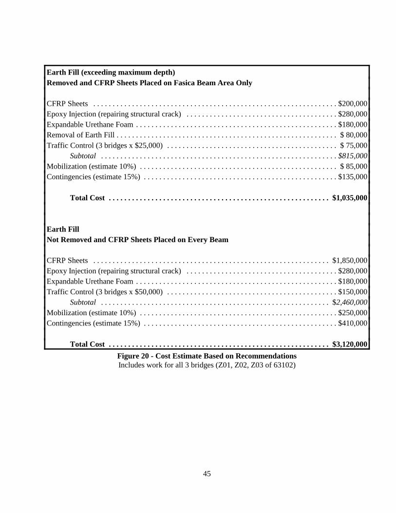
45
Earth Fill (exceeding maximum depth) Removed and CFRP Sheets Placed on Fasica Beam Area Only
CFRP Sheets . . . . . . . . . . . . . . . . . . . . . . . . . . . . . . . . . . . . . . . . . . . . . . . . . . . . . . . . . . . . . . . $200,000Epoxy Injection (repairing structural crack) . . . . . . . . . . . . . . . . . . . . . . . . . . . . . . . . . . . . . . . $280,000Expandable Urethane Foam . . . . . . . . . . . . . . . . . . . . . . . . . . . . . . . . . . . . . . . . . . . . . . . . . . . . $180,000Removal of Earth Fill . . . . . . . . . . . . . . . . . . . . . . . . . . . . . . . . . . . . . . . . . . . . . . . . . . . . . . . . . $ 80,000Traffic Control (3 bridges x $25,000) . . . . . . . . . . . . . . . . . . . . . . . . . . . . . . . . . . . . . . . . . . . . $ 75,000
Subtotal . . . . . . . . . . . . . . . . . . . . . . . . . . . . . . . . . . . . . . . . . . . . . . . . . . . . . . . . . . . . . $815,000Mobilization (estimate 10%) . . . . . . . . . . . . . . . . . . . . . . . . . . . . . . . . . . . . . . . . . . . . . . . . . . . $ 85,000Contingencies (estimate 15%) . . . . . . . . . . . . . . . . . . . . . . . . . . . . . . . . . . . . . . . . . . . . . . . . . . $135,000
Total Cost . . . . . . . . . . . . . . . . . . . . . . . . . . . . . . . . . . . . . . . . . . . . . . . . . . . . . . . . . $1,035,000
Earth FillNot Removed and CFRP Sheets Placed on Every Beam
CFRP Sheets . . . . . . . . . . . . . . . . . . . . . . . . . . . . . . . . . . . . . . . . . . . . . . . . . . . . . . . . . . . . . $1,850,000Epoxy Injection (repairing structural crack) . . . . . . . . . . . . . . . . . . . . . . . . . . . . . . . . . . . . . . . $280,000Expandable Urethane Foam . . . . . . . . . . . . . . . . . . . . . . . . . . . . . . . . . . . . . . . . . . . . . . . . . . . . $180,000Traffic Control (3 bridges x $50,000) . . . . . . . . . . . . . . . . . . . . . . . . . . . . . . . . . . . . . . . . . . . . $150,000
Subtotal . . . . . . . . . . . . . . . . . . . . . . . . . . . . . . . . . . . . . . . . . . . . . . . . . . . . . . . . . . . $2,460,000Mobilization (estimate 10%) . . . . . . . . . . . . . . . . . . . . . . . . . . . . . . . . . . . . . . . . . . . . . . . . . . . $250,000Contingencies (estimate 15%) . . . . . . . . . . . . . . . . . . . . . . . . . . . . . . . . . . . . . . . . . . . . . . . . . . $410,000
Total Cost . . . . . . . . . . . . . . . . . . . . . . . . . . . . . . . . . . . . . . . . . . . . . . . . . . . . . . . . . $3,120,000Figure 20 - Cost Estimate Based on RecommendationsIncludes work for all 3 bridges (Z01, Z02, Z03 of 63102)

Appendix A

63
Z01 of 63102
Although the inspection revolved around the first four post-tensioned box beams, periodic inspections onthe interior beams were performed. The first four box beams were post-tensioned together to carry theweight of the 10-foot tall concrete barrier.
SPAN 1 OVER WESTBOUND I-696
During our June 9, 1998, inspection, we found the following:
West side-
1. The water outlined fascia beam shear cracks ranged in size from 0.003 in. to 0.005 in.2. There were no cracks present on the bottom flanges of the fascia, first, second, or third interior
beams.3. No flexural cracks were visible on the fascia beam.4. There were some shear cracks that extended into the parapet wall.5. Even though the pier end of the beam had more shear cracks than the abutment end, leachate was
hanging from the abutment end and not the pier end.6. One shear crack was present on the inside face of the third interior.7. At the pier end of the beams, all weep holes were plugged and the third interior beam did not have
a weep hole. In order for us to unplug the holes we needed to use a hammer drill. After drillinginto the fascia, first and second beams we found that the Styrofoam was dry. We drilled 8-½inches through the bottom flange of the second interior before we hit the interior of the beam. Noattempt was made to drill through the third interior beam. We were concerned with cuttingprestressing strands.
East side-
1. Along with the flexure cracks, the fascia beam also had shear cracks that ranged in size from 0.005in. to 0.010 in. However, the majority of the crack widths were 0.005 in.
2. At the pier end of the fascia beam, some of the shear cracks had propagated into the parapet wall.3. Water outlined most of the cracks at both the pier and abutment ends of the fascia beam.4. Comparing the pier end with the abutment end of the fascia beam, the spacing of the shear cracks
at the abutment end were spaced closer and appeared wider than at the pier end.5. Moving on to the interior beams, one crack, about 0.003 in., was found on the bottom flange of the
second interior beam.6. The inside web of the third interior beam had a shear crack that has started to wrap around the
beam into the bottom flange.7. Most of the grout placed between the fascia, first, second, and third interior beams, was in good
condition. The exception to this was the grout at the pier end between the fascia and first interiorbeams, which appeared black with efflorescence stains.
8. All of the weep holes on these four beams were plugged. After opening them, we found that onlythe interior of the fascia beam was wet. The remaining three beams were dry.

64
9. From the east fascia, beam numbers 24-27 and 32-37 all had shear cracks roughly 0.003 in. wide.
SPAN 2 OVER EASTBOUND I-696
During our May 19, 1998, inspection, we found the following:
West side-
1. The fascia web had lots of surface hairline alligator cracking and diagonal cracks generally about0.003 in. in size.
2. The grout between the fascia, first, second, and third interior beams was in good condition.3. No cracks were present on the inside edge of third interior beam.4. There were no transverse cracks present on the bottom flanges of the first four beams. 5. There was one longitudinal crack along bottom of fascia beam.6. The weep holes located near the pier in the fascia and fourth interior beams were pre-drilled with
a 3/4 -inch diameter hole. The weep hole in the fascia beam is about 1 ½ inches deep and the holein the fourth interior beam is about 2-½ inches. Neither of these weep holes penetrate the beamcavity since the bottom flange thickness is 6 inches. Note that no prestressing strands were cut ineither case.
East side-
1. The fascia web had leachate extruding from the 0.007 - 0.009 in. diagonal cracks.2. The grout between fascia and first interior beam was darker than the grout between the adjacent
beams.3. When compared to the west side, the east fascia beams were in worse condition.4. We found one diagonal crack in the inside web of the third interior.5. No cracks were found on the bottom flanges of the first four beams.6. The weep holes at the pier end of the fascia, first and second interior beams, were plugged. The
weep hole inserts were installed correctly, but never unplugged. As we unplugged the fascia weephole, water poured from the beam. The cavities of the first interior along with the third interiorwere dry. We were unable to unplug the second interior weep hole.
TOP INSPECTION-
The top of the structure was inspected on May 28, 1998. During this inspection, a conversation with thecity of Southfield park maintenance revealed that the sprinkler heads located on this structure arefrequently broken by vandals. The system runs at night for ½ hour cycles using 3 gallon/minute nozzles.The fourteen heads in the parapet wall areas run Monday, Wednesday, and Friday. I was informed thatlast year the zone above the east fascia failed to shut off and the system ran all night. The entire wood chiparea was flooded. The north manhole drain grate was plugged with wood chips so all of the water stayedabove the beams until he unplugged the grate the next morning. At the time of the inspection, three of theeight sprinkler heads that line the east parapet wall were broken by vandals. All three broken heads werein span 2. With the unit weight of water at 62.4 pcf this adds significant weight. In addition to flooding,the water has added significant weight to the soil itself. At the time of our inspection, there had not been

65
rain in the area for at least a week. However, the soil had a moisture content of 22.6 percent. This highmoisture content is entrapped in the clayey sand that was used for the earth fill. The saturated soilincreases the unit weight of soil from 120 pcf to about 140 pcf.
Part of the top inspection involved determining how much earth fill was present. In order for us todetermine the fill, we dug three holes along the west parapet wall (south abutment, pier, and northabutment) and four holes along the east parapet wall (south abutment, south of the pier, north of the pier,and north abutment). From each location the following was revealed.
West ParapetS. abutment - 3 feet 3 inches of damp sand fillPier - about 4 feet of damp sand fillN. abutment - 4 feet 4 inches dry fill.
East ParapetS. abutment - 3 feet 3 inches dry sandS. of the pier- 4 feet 4 inches depth (bottom 12 inches was saturated sand)N. of the pier- 4 feet 7 inches depth (bottom 12 inches was saturated clay)N. abutment - 3 feet 3 inches depth (bottom 2 feet 3 inches saturated clay)
Visually, the soil elevation along the east parapet wall appears to be about 1 foot below the park elevation.If this is true, then the run off water would drain to the east parapet wall then off to the abutments. Duringour inspection we extracted some of the wet earth fill to bring back to the laboratory for analysis. Fromthis sample we learned that the natural moisture, percent by weight, was 17.6 percent. Through a visualinspection performed by Dan Troia, MDOT Soils Engineer, it was suggested that the unit weight of thesoil was closer to 140 pcf than the 120 pcf stated in the design notes.

66
Z02 of 63102
Although the inspection revolved around the first four post-tensioned box beams, periodic inspections onthe interior beams were performed. The first four box beams were post-tensioned together to carry theweight of the 10-foot tall concrete barrier.
SPAN 1 OVER WESTBOUND I-696
During our June 9, 1998, inspection, we found the following:
West side-
1. The fascia web cracks were generally 0.009 in. wide. 2. One of the numerous outside fascia beam web cracks was 0.025 in. wide. Most of these cracks
were very long and pronounced with water at both the pier and abutment end. 3. A few cracks were also present in the parapet wall.4. Even though there were no visible flexural cracks, this fascia beam had the most shear cracks when
compared with all of the fascia beams inspected.5. Grout was present between the fascia, first, second, and third interior beams. Most of it was in
good condition, however, the grout between the fascia and first interior was cracked at the pier end.
6. Although at least one of the two weep holes per beam end (pier end) were plugged, the interior ofthe beam appeared dry.
7. There were no cracks present on the inside web of the third interior beam.
East side-
1. The 0.002 in. wide fascia web cracks were water stained but were not wet. 2. However, the cracks at the abutment end of the fascia beam were outlined with water. 3. No cracks were found on the bottom flanges of the fascia, first, second, or third interior beams. 4. Also, no cracks were present on the inside web of the third interior beam. 5. Some of the weep holes in the pier end of the first four beams were plugged, however, the interior
of the beams appeared dry. 6. Some flexure cracks were present in the fascia beam. Also some shear cracks were present in the
retaining wall. 7. The grout between the fascia, first, second, and third interior beam was in good condition.8. All four post-tensioning ducts had water staining the grout pockets.9. The interior beams on the east side were in good condition.

67
SPAN 2 OVER EASTBOUND I-696
During our May 19, 1998, inspection, we found the following:
West side-
1. The 0.009 - 0.016 in. diagonal fascia web cracks were wet with no leachate present. 2. One of the diagonal cracks on the fascia beam extended about 4 feet in the parapet wall. 3. The fascia beam web was also severely alligator cracked. 4. When compared with the surrounding keyway grout, the grout between the fascia and first interior
was darker and had more spalls.5. The beams on this structure had two weep holes per location instead of the single weep hole as
Z01.6. Probing the pier end weep holes in fascia, first, second, and third interior beams revealed that the
insides of the beams were dry. However, due to the water stains surrounding the holes it appearsthat water does drain through the beams.
7. The inside web of third interior was in good condition (no cracks).8. There were no diagonal cracks in the bottom flanges.9. Two longitudinal cracks were present on the bottom flange of the third interior beam.10. The grout between second and third interior looks like it might fall.
East side-
1. At the time of our inspection, the 0.005 in. diagonal fascia web cracks were wet and withoutleachate.
2. When compared to the west fascia, the east fascia was in better condition.3. The keyway grout between the first four beams was in good condition.4. All weep holes at the pier end of the first four beams were dry with efflorescence on the outside
surface.5. No cracks were found in bottom flanges or on the inside edge of the third interior beam.
TOP INSPECTION-
The top of the structure was inspected on June 9, 1998. From this inspection we discovered that asprinkler system is present, however, no sprinkler heads are present directly in front of the parapet wall.They are placed inward from the wall and spray toward it. There is also a valley between the wall and thesidewalk. It appears as though water drains through the valley toward the parapet wall then off to theabutments.
We arrived at 9:00 a.m. for our inspection. At this time the valley between the sidewalk and west parapetwas not saturated. It was just wet. However, the valley near the east parapet wall had standing water, eventhough that night there had been no rain. The only source of water was the sprinkler system. Numeroussprinkler heads were found between the sidewalk and the parapet wall.

68
One interesting point, two of the original twenty trees that lined the west parapet wall were cut down. Asfor the pine trees that lined the east parapet wall, seven of the original seventeen were cut down and fourof those seven were located above the pier.
Part of the top inspection involved determining how much earth fill was present. In order for us todetermine the fill, we dug three holes along the west parapet wall (south abutment, pier, and northabutment) and five holes along the west parapet wall (south abutment, pier (three holes), and northabutment). From each location the following was revealed.
West Parapet
S. abutment - 6 feet 0 inches of damp sand fill - the last 3 inches was saturated clayPier - 4 feet 0 inches of saturated sand N. abutment - 3 feet 6 inches of fill - the last 1 feet 10 inches was moist clay
East ParapetS. abutment - 4 feet 0 inches of sand fill - the last 1 foot was wet sandPier - 4 feet 0 inches of sand fill - the last 2-½ feet was wet sand10 feet from the parapet wall above the pier - at 3 feet 0 inches we encountered unmovable moistclay *15 feet from the parapet wall above the pier - 3 feet 10 inches of fill - 3 feet 2 inches of saturatedclay and the last 8inch was saturated sand * N. abutment - 3 feet 6 inches of moist clay
*After two hours, no water had leached in the holes.
During our inspection we extracted some of the wet earth fill to bring back to the laboratory for analysis.From this sample we learned that the natural moisture, percent by weight, was 22.6 percent. Through avisual inspection performed by Dan Troia, MDOT Soils Engineer, it was suggested that the unit weightof the soil was closer to 140 pcf than the 120 pcf stated in the design notes.

69
Z03 of 63102
Although the inspection revolved around the first three box beams, periodic inspections on the interiorbeams were performed. The first three beams were closely inspected because the fascia beam carries theentire weight of the parapet wall and the second interior beam resists the torsional forces created by theearth fill against the parapet wall. The torsional forces are carried through a turnbuckle assembly that isattached to the parapet wall and the second interior beam. This was the first of the three plaza structuresto be constructed.
SPAN 1 OVER WESTBOUND I-696 During our June 9, 1998, inspection, we found the following:
West Fascia-
1. The dry fascia web cracks ranged in size from 0.003 to 0.005 in.2. Only one crack was found on the bottom flange of the fascia beam. This crack was roughly 0.005
in. wide.3. No cracks were found on the inside web of the fascia beam. This beam was in great condition
when compared with the other fascia beams. It was noticeably better than the east fascia. 4. No cracks were found on the first, second, and third interior beams. 5. The weep holes on the pier end of the fascia beam were plugged. 6. The weep holes on the pier end of the first, second, and third interior beams were all open. The
interior of these beams appeared dry. 7. The abutment end of the fascia beam has about the same amount of cracking as the pier end. 8. Four ducts were present for the longitudinal tie rods.9. No flexure cracks were present on the fascia beam.
Beam number 54 from the west fascia had a collection of water on the midspan of the bottomflange. The 27th beam from the west fascia did not have cracks. This beam was inspected becausethe 27th beam from the east fascia in the eastbound half had very large cracks.
East side-
1. The width of the water outlined fascia web shear cracks were mainly 0.005 to 0.009 in.2. The fascia beam end near the abutment had more cracks than the pier end.3. Longitudinally across the fascia beam a crack that appeared to outline the bottom flange was
visible.4. No cracks were found on the inside web nor on the bottom flange of the fascia beam.5. Shear cracks were found on both webs of the first interior and second interior beams.6. No flexure cracks were visible on the fascia beam.7. The fascia beam had fewer cracks than the interior beams on this structure.8. A few shear cracks were present in the barrier wall.9. From the interior bottom flanges, stalactites have formed from the leachate.10. Each beam end has two weep holes.
70
11. All of the first four beam ends located near the pier were dry, however, two of the plastic draincaps were still in place.
12. The beam spacing between the fascia and first interior was 1-3/4 inches this seemed largecompared to the adjacent beam spacing of 7/8-inch to 1 inch.
13. From the east fascia beam numbers 4-11, 13, 15-19, and 32-35 all have cracks through the bottomflange in the location of the weep holes. Beams 32-35 have very large shears cracks about 0.040in. in width. Each of these beam ends have numerous cracks. The shear cracks in the web areoffset. Although these beams are in far worse shape than the fascia beams, there is no evidenceof water.
SPAN 2 OVER EASTBOUND I-696
During our May 19, 1998, inspection, we found the following:
West side-
1. The diagonal fascia web cracks were mainly 0.007 in. in width.2. No cracks were present on inside web of fascia beam.3. The first interior beam had diagonal cracks along both webs along with two longitudinal cracks
on the bottom flange. The flange cracks appeared to have originated from the weep holes.4. The second interior beam had no cracks on the bottom flange nor on the outside face of the web.5. The interior portion of the fascia, first and second interior beams, were dry at the weep holes
locations.6. At least twelve interior beams have shear cracks at the beam ends. From the west fascia beams
number 6, 8, 9, 11, 15, 18, 19, 20, 24, 25, and 27 have transverse cracks in the bottom flanges.Beam number 27 had a shear crack width larger than 0.060 in.
7. On top of the structure, there is a roadway approximately 160 feet to 195 feet from the west fascia(Church Road). This road looks recently re-paved. It is posted no trucks and is very busy withcars. Also, there is a large parking lot about 230 feet from the west fascia. From the plans, beamnumber 27 is approximately 115 feet from the west fascia. The measured dimensioning for theroadway may be slightly off because we were unsure of the location of the pier. We guessed at thepier location due to a diagonal crack in the west side walk that we believed was the approximatelocation of the pier.
8. It appears that elevation of Church Road is lower than that of the fill around the west parapet wall.
East side-
1. The water stained, diagonal fascia web cracks were mainly 0.005 in. wide.2. There were no cracks on the inside face of the fascia beam.3. The grout between the fascia beams of span 1 and span 2 was saturated.4. There were no cracks present on the bottom flanges of the fascia, first and second interior beams.5. No web cracks were present on the first interior or second interior beams.
71
TOP INSPECTION-
The top of the structure was inspected on May 28, 1998. As part of the inspection, we wanted todetermine the amount of fill present. Therefore, we dug three holes along the west and east parapet wall(south abutment, pier, and north abutment). From each location the following was revealed.
West ParapetS. abutment - 3 feet 8 inches depth (the top 3 feet was very dry and hard and the bottom 6 inches
was wet granular material)Pier - 3 feet 0 inches to large aggregate - we were unable to remove the aggregate (the fill
and the aggregate were dry)N. abutment - 2 feet 0 inches to large aggregate - we were unable to remove to top of beam (fill
and aggregate were very dry)
East Parapet
S. abutment - 5 feet 5 inches depth (about 8 inches of wet open graded material past thegeotextile blanket)
Pier - 5 feet 2 inches depth (about 8 inches of wet open graded material past thegeotextile blanket)
N. abutment - 4 feet 4 inches depth (bottom of hole was moist).
Note: Holes stopped at geotextile blanket, which is on top of open graded drainage course.
The area around the west parapet wall is lined with pine trees. No trees are present along the east parapetwall. Also a sprinkler system is present, however, it appeared as though there are no sprinkler heads thatspray water near the parapet walls.


