Page 1
Investigation of wear behavior of different sliding bearing materials in an alkaline environment
Undersökning av nötningsbeteendet av olika glidlagermaterial i en alkalisk
miljö
Martina Ottoson
Faculty of Health, Science and Technology
Degree Project for Master of Science in Engineering, Mechanical Engineering
30 Credits
Supervisor: Pavel Krakhmalev
Examiner: Jens Bergström
Date: 2018-07-18
Page 3
Abstract
In sliding bearing wear is a very common problem and can be affected by several factors. The
wear in a bearing can lead to total failure of the component and lower the lifetime. In a sliding
bearing used in a machine in the pulp and paper industry large wear has been detected, but no
clear evidence of what the wear depends on. The environment in the machine is strong alkaline
(pH 14), a solution of white liquor and lime mud. The penetration of this solution into the
bearing might lead to increased wear. A wear study and test were done to see if a better material
choice could reduce the wear.
In this project an investigation of the wear for seven different bearing materials was done. Two
cobalt-based alloy Stellite 6 and Stellite 12, two different precipitation hardened martensitic
stainless steel with different number of alloying elements, 17-4PH and Endotec 04. The
different metals were welded on the pin with a minimum of 3mm. The other material was three
different PEEK polymer composites. PEEK HPV reinforced with carbon fiber, PTFE and
graphite. PEEK CA30 with carbon fibers and PEEK GF30 with glass fiber.
The method used for the wear test was grinding machine that was reconstructed to a pin-on-
disc tribology test. The tests were executed in room temperature with sliding speed of 150rpm
and duration of 20 minutes. The metals were tested with the solution of white liquor mixed with
lime mud, at two different loading conditions of 300N and 550N. The polymer composites were
tested at the load of 300N but with different solution present, white liquor mixed with lime mud
and with water. All the pins were sliding against a disc of austenitic stainless steel.
Equipment used to investigate the wear mechanisms was a scanning electron microscope. The
wear rate was measured by weighing of the pin before and after each test. How the material
was affecting the roughness of the austenitic steel countersurface was done with the
profilometer.
The results of this work showed that both Stellite 6 and Stellite 12 was almost wear resistance
in the condition similar to the bearing. Endotec 04 also showed low wear and 17-4PH had the
highest of the metals. The dominant wear mechanism seemed to be different severity of
adhesive wear. The polymer composite showed all higher wear than the metals, the reason to
the high wear rate was harder to decide. It might be a combination between adhesive wear,
pulverization of fibers, adsorption of calcium carbonate and matrix/fiber interfacial removal.
The alkaline liquid was also believed to increase the wear of the polymer and adhere to some
of the metals. The metals seemed to increase the roughness of the countersurface, but the
polymers seemed to have more of a polishing effect.
Page 5
Sammanfattning
I ett glidlager är nötning ett mycket vanligt problem och kan bero på många olika faktorer.
Nötning i ett lager kan leda till haveri av hela komponenten och sänker livslängden. I ett
glidlager som används i pappers och massaindustrin har stor nötning upptäckts, men inga
tydliga orsaker till vad nötningen kan bero på. Miljön i maskinen är stark alkalisk (pH 14), en
blandning mellan vitlut och mesa. Om denna lösning kommer in i lagret kan det möjligtvis leda
till ökad nötning. En nötningsstudie och tester gjordes för att se om ett bättre materialval kan
leda till minskad nötning.
I detta projekt gjordes en undersökning av nötning för sju olika lagermaterial. Två cobolt-
baserade legeringar Stellite 6 och Stellite 12, två olika utskiljningshärdade martensitiska rostfria
stål med olika mängd av legeringsämnen, 17-4PH och Endotec 04. Alla metaller var svetsade
på pinnarna med en 3mm minimum tjocklek. De andra materialen var av tre olika PEEK
polymera kompositer. PEEK HPV förstärkt med kolfiber, PTFE och grafit. PEEK CA30 med
kolfiber och PEEK GF30 med glasfiber.
Metoden som användes för att bestämma nötningen var en omkonstruerad stav-på-platta
tribologitest. Testet utfördes i rumstemperatur med en hastighet på 150 rpm och en varaktighet
på 20 minuter. Metallerna testades med lösningen av vitlut blandat med mesa, med två olika
laster på 300N and 550N. Polymer kompositerna testades med en last på 300N men med olika
lösningar, vitlut blandat med mesa och en annan med vatten. Alla pinnar gled mot en disk av
autentiskt rostfritt stål.
Utrustning som användes för att undersöka nötningsmekanismerna var ett skanning
elektronmikroskop. Nötningshastigheten mättes genom att väga pinnarna efter varje test. Hur
materialen påverkade ytjämnheten av motytan av austenitiskt stål gjordes med en profilometer.
Resultatet av arbetet visade att både Stellite 6 och Stellite 12 var nästan nötbeständiga i ett
tillstånd som liknar lagret. Endotec 04 visade också låg nötning och 17-4PH hade den högsta
av metallerna. Den dominanta nötningsmekanismen visade sig vara olika grader av adhesiv
nötning. Polymer kompositerna hade alla högre nötning än metallerna, men orsaken till den
höga nötningen var svårare att förklara. Det kan vara en kombination mellan adhesive nötning,
pulverisering av fibrer, adsorption av kalciumkarbonat och förlorad matris/fiber kontakt.
Metallerna ökade ytjämnheten för motytan, men polymererna verkade ha polerings effekt.
Page 7
Acknowledgement
This master thesis has been carried out in partial fulfilment of the requirements for the degree
of Master Science in Mechanical Engineering at Karlstad University, Sweden. I want to thank
Valmet which gave me the opportunity to do my master thesis for them and a special thanks to
my supervisors at Valmet Henrik Ransjö and Patrik Björnvall for the help and support.
I would also like to express my gratitude to my supervisor at Karlstad University, Professor
Pavel Krakhmalev who always had time for my questions, helped and guided me during my
thesis. Finally, I would also like to send a thank to research engineer Christer Burman for the
help with the investigation machines.
Martina Ottosson ----------------------------------------------------------------------------------------------------------------------------------------------------------------
Authors Signature
City and Date: Karlstad, July 2018.
Page 9
Table of Contents
1 Introduction ........................................................................................................................ 1
1.1 Background .................................................................................................................. 1
1.1.1 About Valmet ....................................................................................................... 1
1.1.2 The component ..................................................................................................... 1
1.1.3 Thesis problem definition ..................................................................................... 2
1.2 Tribology ..................................................................................................................... 3
1.2.1 Sliding Friction ..................................................................................................... 3
1.2.2 Surface roughness ................................................................................................ 3
1.3 Wear ............................................................................................................................. 4
1.3.1 Adhesive Wear ..................................................................................................... 5
1.3.2 Abrasive Wear ...................................................................................................... 7
1.3.3 Abrasion of Multiphase and reinforcement Materials .......................................... 9
1.3.4 Erosive Wear ...................................................................................................... 10
1.3.5 Corrosion and Oxidative Wear ........................................................................... 10
1.3.6 Fatigue wear ....................................................................................................... 12
1.3.7 Wear of metals in different PH environment ..................................................... 13
1.4 Wear of Polymers based composites ......................................................................... 15
1.4.1 Wear of polymer composites in water lubrication ............................................. 17
1.4.2 Corrosion of Carbon Fiber ................................................................................. 18
1.4.3 Polymers in alkaline environment ...................................................................... 19
1.5 Parameters affecting wear in sliding bearing ............................................................ 19
1.5.1 Misalignment ...................................................................................................... 19
1.5.2 Grooves .............................................................................................................. 20
1.5.3 Materials ............................................................................................................. 20
1.5.4 Temperature ....................................................................................................... 21
1.6 Material study ............................................................................................................ 21
1.6.1 Cobalt alloys ....................................................................................................... 22
1.6.2 PEEK Composite ................................................................................................ 23
1.6.3 Stainless Steel ..................................................................................................... 24
1.6.4 Nickel-based-superalloys ................................................................................... 25
1.6.5 Iron-based superalloys ........................................................................................ 25
1.7 Aims and purpose ...................................................................................................... 26
2 Method and Material ........................................................................................................ 27
Page 10
2.1 Test Material .............................................................................................................. 27
2.2 Execution of Test ....................................................................................................... 28
2.2.1 Construction of the wear test .............................................................................. 28
2.2.2 Wear Test conditions .......................................................................................... 30
2.3 Investigation of Wear ................................................................................................ 30
2.3.1 Wear rate ............................................................................................................ 30
2.3.2 Scanning Electron Microscope ........................................................................... 31
2.3.3 Profilometer ........................................................................................................ 32
3 Results .............................................................................................................................. 33
3.1 Wear ........................................................................................................................... 33
3.1.1 Wear rate ............................................................................................................ 33
3.1.2 Evaluation of wear mechanisms of pin material in SEM ................................... 36
3.2 Investigation of Worn Countersurface ...................................................................... 42
4 Discussion ........................................................................................................................ 47
4.1 Wear ........................................................................................................................... 47
4.1.1 Metals ................................................................................................................. 47
4.1.2 Polymer composite ............................................................................................. 48
4.2 Worn countersurface .................................................................................................. 50
4.3 Comparison of metal and polymer in the real application ......................................... 51
4.4 Error Effects .............................................................................................................. 52
5 Conclusion ........................................................................................................................ 53
6 Future work ...................................................................................................................... 54
7 References ........................................................................................................................ 55
8 Appendix .......................................................................................................................... 59
Page 11
1
1 Introduction
This Master thesis was done at Karlstad University in collaboration with Valmet. In one of the
process machine in the pulp and mass production, wear has been detected in a sliding bearing.
A study was done to see if a material choice with regard to wear mechanisms, environment and
operations parameter can reduce wear.
1.1 Background
1.1.1 About Valmet
Valmet is a leading global company of technology, automation and service in the pulp, paper
and energy industries. Valmet gives their customers high service, it includes everything from
outsourcing of maintenance to spare parts and improvements factories and facilities. They also
have a wide technology range that includes both entire pulp mills and production lines for tissue,
cardboard and paper. Valmet has production of advance automation solutions range, in some
case just for single measurement but also for automation projects for entire plants.
Valmet has around 1500 employees in Sweden and costumers all around the world. In Sweden
three out of four paper mill is produced by Valmet. In 2013 the business for pulp, paper and
power businesses became independent. Valmet has a vision to become a champion in service
to their global costumers and they work for it every day [1].
1.1.2 The component
One process machine in the paper mill factory is called Slaker. In this machine the burned lime
is added to the green leaching solution. Which generate a lot of lime gravel that has to be
removed from the process, which is done with a sorting screw that can be seen in Figure 1.
Lime gravel is unreacted lime as well as inert substances that have entered the process through
the wood raw material. The environment in the machine is green leaching solution with a pH
grade of 14.
Figure 1: Transportation screw in the process machine slaker.
Page 12
2
Green leach solution mixture consists mainly of soda (sodium carbonate), but also sulfite,
sulfate and sulfide of sodium, as well as contamination that gives it the green color. [2] The
other product in the slurry is lime mud, which is calcium carbonate. Lime mud has a gray color
and a substance like mud or clay. [3]
The lower part of the screw is completely immersed in the liquid but the upper part is in contact
with air (oxygen). In the bottom of the screw there is a sliding bearing construction, see Figure
2.
Figure 2: Sliding bearing construction.
Today it is water flowing through in grooves in the bushing, to have some lubrication but also
remove particle and dirt in the bearing.
1.1.3 Thesis problem definition
Over the years, there have been many challenges with this sliding bearing, because of its
vulnerable environment. Damage and wear has been detected on the bushing. Several solutions
have been tested, with different seals and water flow channels and material combinations of
axel and casing. One possibility to the wear might be that the lime particles comes into the
bearing and causing abrasive wear, but also the white leaching solution can enter the bearing
and corrosion also might be a factor. Because of these challenges an investigation about the
material selection and the materials different wear behavior in the alkaline environment will be
made.
Page 13
3
1.2 Tribology
Tribology is the study of two surfaces in relative motion, it comes from the Greek word ‘tribos’
which means rubbing or sliding. In tribology the main focus is on the friction, wear and
lubrication, all these factors are depending on each other in some ways [4].
1.2.1 Sliding Friction
When two surfaces are sliding against each other, there will appear a tangential force that resist
the movement of the surfaces, this resistance force is defined as the friction. The coefficient of
friction (𝜇) is defined as the frictional force (𝐹) divided by the normal force (𝑁), equation (1).
The coefficient of friction is not a material parameter, it is a system parameter [5].
𝜇 =
𝐹
𝑁 (1)
It is generally four laws of friction:
1. The friction force is proportional to the normal load.
2. The friction force is not dependent of the apparent area of contact.
3. The friction force is not dependent of the sliding velocity [6].
The friction is usually divided into two terms. The adhesion coefficient of friction, equation (2),
which is related to the asperity contact. Where s is the shear strength and H is the hardness of
the material. Asperity in contact create contact bridges which will yield when the shear stress,
created in the material during sliding, will reach the weaker materials yield stress in pure shear.
Therefore, the frictional resistance is created from the contact bridges that will be sheared and
eventually breaks.
𝜇𝑎𝑑ℎ =𝑠
𝐻 (2)
The deformation coefficient of friction, equation (3), where the 𝛼 is the semi-angle of a rigid
conical asperity. This equation is related to the force that is needed for the harder materials
asperities to plow in the softer material surface, 𝐹𝑑𝑒𝑓 and W is the normal load. This
contribution to the friction is more related for rougher surfaces [7].
𝜇𝑑𝑒𝑓 =
𝐹𝑑𝑒𝑓
𝑊=
2
𝜋𝑐𝑜𝑡𝛼 (3)
1.2.2 Surface roughness
Surface roughness are strongly affecting the friction, lubrication and wear. Therefore,
roughness analysis is often done to see the surface morphology after a wear test. [8]
Page 14
4
The most used surface parameter is the average roughness, Ra. Which is the arithmetic average
of the absolute values of the profile height deviation from the mean line, in a certain given
length, L, that is being analyzed, Figure 3. The average roughness mathematical formulation is
defined as equation (4).
𝑅𝑎 =
1
𝐿∫ |𝑧(𝑥)|
𝐿
0
𝑑𝑥 (4)
Where z is the height of the peaks above the mean line with a certain distance x from the origin
[6]. The roughness Ra for a journal bearings axel and bushing is recommended to be kept under
1𝜇𝑚 to be able to control wear [9].
Figure 3: Illustration of average roughness curve.
1.3 Wear
A good definition of wear is; damage of a solid surface that often but not always involves loss
of material, the wear of each material is depending on the relationship between the surfaces and
the contact of the substrate or substrates. Knowledge about the mechanics, physics, chemistry,
and material science is an important part to understand the wear in more detail and its
mechanisms. In applications like bearing, wear and friction is a main concern. The composition
and properties of the materials surface and near-surface regions will change during the wear
process. Change in surface topography will also be a factor during wear. Which mechanisms
that occur during the wear process is often complex, it often involves a mixture of mechanical
and chemical processes [10].
General classification of wear parameters, and description of the wear mechanisms are shown
in Table 1.Wear mechanisms is often classified as mechanical, chemical and thermal. Into the
mechanical class the abrasive, adhesive, flow and fatigue wear mechanisms are related. The
chemical wear class is controlled by the formation of a chemical reaction film. Thermal wear
is associated with local surface melting, which is formed through frictional heating [10].
Archard equation is often used when sliding and abrasive wear is described, equation (5).
Page 15
5
It relates the volume wear per unit sliding distance, by using macro properties W, the normal
load, and H, the hardness of the softer surface. Where the constant K is called the wear
coefficient and is of great importance to be able to compare the severity of wear in different
tribology systems [6]. The coefficient of wear is influenced by a lot of parameters like pressure,
temperature, surface roughness, materials, velocity and lubricant [9].
Many materials experience a running-in period until the equilibrium surface condition have
become established. In the running-in period the wear rate can either be higher or lower than
the equilibrium condition [6].
To characterize the tribology behavior of material in laboratory, standard test like pin-on-disc
is often used. From this test the wear parameters like worn mass and specific wear rate can be
measured and calculated [10] [11].
Table 1: Classification of wear parameters [10]
1.3.1 Adhesive Wear
Adhesive wear is one common kind of wear mechanism during sliding of two surfaces in
contact. When the asperities of two material gets in contact they can adhere to each other in
𝑄 = 𝐾
𝑊
𝐻 (5)
Page 16
6
form of atomic contact. For plastic dominated wear the asperities will be deformed due to shear
forces that are added during sliding, which can lead to different wear mechanisms to be present
[4].
The adhesive wear mechanisms can lead to removal of lumps from either or both of the surfaces
in contact. One mechanism is when plastic flow of an asperity leads to detachment of a wear
debris. In this mechanism plastic shearing of successive layer occur. Which means that adhesive
forces are not necessary to remove material, it depends mainly on the mechanical interaction of
the asperities [6].
Another mechanism is when the debris, that has been formed by asperities rapture, generate an
adhesive transfer to the countersurface. On the countersurface the transferred material can form
a new asperity, lager wear particle can be generated, eventually the transferred material will be
compressed and spread out due to further sliding. Illustration of this wear mechanisms can be
seen in Figure 4 [6].
Figure 4: Illustration of the adhesive wear transfer mechanism. [6]
The third mechanism that has been found during sliding wear is related to the delamination
theory, which involves plastic deformation beneath the surface and formation of cracks that
eventually extend up to the surface and a plate-like wear particle become detached. Such plate-
like wear debris are often found during sliding wear of metals [6].
Page 17
7
Metal-metal surface contact has shown to get a strong adhere contact, but some differences
between particular element has been indicated. Metals has four different type of crystal
structure; face-centered cubic structure (fcc), body-centered cubic structure (bcc), hexagonal
close-packed (hcp) and tetragonal. Experimentally studies have shown that metals with same
hardness but a crystal structure of HCP has lower adhesion compared to other structure. This
can be explained by; to get true contact in form of adhesion between the asperities, some plastic
deformation is necessary. The HCP structure has much less slip system and exhibit a lower
ductility compared to BCC and FCC, therefore show lower adhesion [4].
Chemically active surface bonds easier to another surface and therefore exhibit stronger
adhesion, therefore ‘chemical reactivity’ or electropositivity also influence the adhesion of
metals [4]. It has also been shown that adhesive wear is more often present and more severe
between two similar materials than for two dissimilar pairs [6].
1.3.2 Abrasive Wear
Abrasive wear is a form of wear when material is removed or displaced from the surface caused
by a hard particle between the surfaces sliding against each other. But it can also be in forms of
hard protuberance on the countersurface. These particles can cause different wear mechanisms,
which ones that will be present depends on the properties of the surface material but also on the
properties of the abrasive particles [6].
Abrasive wear is usually divided into two kinds of modes, if the damage is caused by particles
that are free to roll and slide between the surface it is called three-body abrasive wear, if the
damage is done by a fixed protuberance it is named two-body abrasive wear [6]. Figure 5
illustrate the difference between the two modes. Experimental studies has shown that two-body
abrasive wear is much more severe than the three-body [4].
Figure 5: Illustration of the two different modes in abrasive wear. [4]
Page 18
8
Present mechanisms in abrasive wear can be characteristic of both plastic flow and brittle
fracture. These mechanisms often occur together but, in some cases, plastic flow can occur
alone. The dominant wear mechanisms for plastic deformation are three different types, cutting,
ploughing and wedge formation. Cutting is when material is detached from the surface in form
of a chip, the chip forms through a shear zone that flows up in the front face of the particle. In
the ploughing mode no material is removed from the surface, the deformed material is pushed
ahead of the particle. Wedge formation is a mix between the cutting and the ploughing mode,
material is removed from the surface through a raised ‘prow’ that forms through the growth of
deformation and eventually detach from the surface [6].
When the material has characterized of brittle type, the abrasive particle will form cracks at
higher loads. Different kinds of cracks can be present, for more angular particles the median
vent crack and lateral vent crack are present, for a blunter particle the Hertzian cone crack will
appear. These cracks can lead to large detachment of material in forms of big flakes [6].
Influence of the Abrasive Particle
The properties of the abrasive particles have a great influence of how severe the wear will be.
Factors that plays a great roll is the shape, hardness and size of the particles. If the hardness of
the particle is lower than of the surface much less wear is caused. But if the hardness is much
more significant than of the surface it matters less [6].
The abrasive particle will only cause a plastic indentation only if the hardness of the surface,
𝐻𝑠, is less than 0.8 times the hardness of the abrasive particles, 𝐻𝑎. This is affected by the
maximum contact pressure that can be achieved for a spherical particle is about 0.8 of the
indentation hardness of the particle material. If this is not the case, plastic flow will occur in the
abrasive particle and it will be bunted. In Figure 6 this is illustrated, the two different modes
are sometimes termed hard abrasion when 𝐻𝑎/𝐻𝑠 > 1.2 and soft abrasion wear when 𝐻𝑎/𝐻𝑠 <
1.2 [6].
Figure 6: Illustration of different contact between the grit and surface, under normal load and plain surface a) particle intent
the surface b) particle become blunted. [6]
The wear rate is also strongly affected by the shape of the particle, an angular particle is causing
significant higher wear than a rounded particle. For a more angular particle microcutting is the
most present mechanisms and a more rounded particle microploughing are more dominant. The
particle size has also an impact on the wear, a bigger particle causes more severe wear than a
Page 19
9
smaller one, for a smaller volume it is harder to move dislocations and therefore flow stress for
a small volume is lower than for a larger volume [12].
1.3.3 Abrasion of Multiphase and reinforcement Materials
Materials with a soft matrix and a hard phase like steels with carbides, cobalt-based alloys
(Stellites), white cast iron and metals with cemented carbides are often used in abrasion wear
conditions. But, composite materials with reinforced particles are also often used in wear
applications [6].
Abrasion of multiphase material is a complex process and several factors are affecting the
mechanisms that might be present. One important factor is the microstructure of the material
and its behavior. Other factor like mechanical properties, loading condition, environment and
things discussed earlier, the properties of the abrasive particles, are all influencing the wear of
the composite [13].
The reinforcement or hard phase volume fraction, size and distribution properties have shown
to have a powerful impact to the resistant to abrasive wear [6]. A higher volume fraction
increased the resistance to abrasive wear, but only to a certain critical volume where the
resistance seemed to decrease. This critical volume is different for different composite materials
and is affected by the interfacial bonding strength of the reinforcement phase and the matrix.
The composite became more brittle and fracture easier when the critical volume was reached,
which decreased the wear resistance [13]. Therefore, a high volume of the hard phase does not
always lead to high resistance to wear, there must be a good combination between the hardness
and the toughness of the matrix, to also withstand fracture [6].
The size of the reinforcement particle also has a great influence of abrasive wear. A large
particle can resist the abrasive force better than a smaller one, but the smaller one has shown to
strengthen the matrix, which leads to that it is more difficult for the abrasive particle to cause
wear of the softer matrix. Hence a combination between both small and large reinforcement has
a greater resistance to abrasive wear then a single-sized. This phenomena also depends on the
abrasive particle size [13].
The size of the hard phase is also affected by the deformation caused by the abrasive particle,
that depends on the depth or the width of the indentation of the abrasive particles. If the abrasive
particle indentation is much greater than the hard phase, the material will act as a homogenous
solid, which can be seen in Figure 7 a). But if the hard phase is about the same size or larger
than the indentation it will act heterogeneously, as seen in Figure 7 b) [6].
Page 20
10
Figure 7: Illustration of how the indentation and contact zone of the abrasive particle is affected by the hard phase or the
reinforcement phase a) is the homogenous behavior, and b) is the heterogeneously behavior. [6]
Different phases in steel, with the same hardness, has shown different abrasive wear resistance
due to various ductility and strain-hardening rate during abrasive wear [6]. Changes of the
microstructure and work-hardening rate during abrasion has a great influence of controlling
wear resistance of the material. Increased hardness of the surface during the abrasion process
has indicated increases of the wear resistance [12].
Retained austenite is good to have in the structure, because it exhibits high ductility and strain-
hardens during abrasion which has showed to give high resistance to abrasive wear. Higher
amount of carbides and also coherent particles has seen to increase abrasive resistance [6].
According to F.Parreiras observation of Cobalt-chromium alloys the abrasive particle changed
wear tracks when they hit the hard carbides, and the wear at the hard phase was much less than
at the matrix [14].
1.3.4 Erosive Wear
Wear can also be caused by hard particles striking the surface. The amount of wear depends on
the number and mass of the particles, and its velocity when it striking the surface. Erosion can
also be in form of wet erosion, when rapid flowing liquid is impacting the surface or solid
particles are present in a liquid flow [15].
In the same way as for abrasive wear the erosive wear mechanism can involves both plastic
deformation and brittle fracture. The impact angle of the striking particle has a great influence
of which wear mechanisms that will be present. At lower angle around 20-30° the dominant
mechanism is of plastic character and at higher angle 90° the brittle will be more dominated [6].
1.3.5 Corrosion and Oxidative Wear
Corrosion wear is defined as a tribochemical reaction between the surface material in contact
and the surrounding media that forms thin films. The surrounding media could be air, vacuum
or a liquid lubrication. [10] Corrosive wear usually called “tribocorrosion”, is related to any
form of mechanical wear (adhesive, abrasive, erosive, fatigue, fretting, etc.) that occur in
combination with chemical or corrosive process [4].
Page 21
11
When a metal is producing corrosion products at the surface and at the same time subjected to
sliding contact there are mainly four processes that can occur:
1) Formation of a sustainable thin film that lower corrosion and wear
2) Formation of a very weak film that has short lifetime during sliding contact and high
rate of wear may be present because of destruction and regrowth of the film
3) The protective film can be worn out by pitting and galvanic coupling between the
film and substrate appear, causes rapid localized corrosion of the worn area
4) Independently corrosive and wear process causes a material loss which is the sum
of these two processes added together
Figure 8: illustration of four different corrosion mechanisms present at sliding. [4]
All the four different processes are illustrated in Figure 8. Process number one is dominated
when a durable corrosion product layers forms and can act as lubricating films. But very few
corrosion products are good enough to withstand mechanical wear that occurs. Process number
two is the most common corrosive wear during sliding and creates wear debris of the weak
corrosion product film. When the passivating film has been removed by wear, corrosion occur
in the ‘active areas’ of the worn surface. The active areas are equal to the true area of contact.
Process three and four is a more severe type of corrosion wear [4].
Synergism between corrosion and abrasive wear
Corrosion wear causes much more wear loss than static corrosion alone. Present of wear by
hard particle in form of abrasion and erosion can accelerate corrosion by removal of the
passivating films, which can lead to rapid form of material loss. This is a typical mechanism in
the processing industries where slurries contain corrosive chemical with combination of
abrasive grits that has to be transported. A model of how the corrosive-abrasive wear is acting
is illustrated in Figure 9, which shows a cyclic formation of film that is removed by corrosive
Page 22
12
and abrasive action. When the particle is instead removing the material by impacting the surface
with high energy the mechanism is often called erosion-corrosion [4].
Figure 9: Illustration of abrasive-corrosion mechanism. [4]
When abrasive wear is dominated the corrosive effect become insignificant. This can be
explained, when corrosion is slow compared to the abrasion the grit will be removing more
underlaying material that doesn’t involve the corrosion film. Oxide that is formed during
corrosion is much harder than the substrate material, this can lead to an accelerating wear [4].
Oxidative wear
When oxygen is present around the surface, majority of metal creates a thin layer of oxide. This
oxide layer prevents the wear of the metal by lowering the shear strength at the surface and
lowering the metal-metal contact at the asperities [4].
Oxidative wear is defined as; when oxide wear debris is formed. Increased temperature,
continuous removal of the oxide or by mechanical interaction of the oxide can lead to increased
oxidative grow rate. Oxide wear is seen as a mild form of wear, because it protects the metal to
be worn out. The oxide growth is strongly increased during sliding, that can be explained by
the increased diffusion rate [6].
1.3.6 Fatigue wear
During sliding the top-layer material directly below the surface is exposed to very high
deformation. This deformation is caused by shearing force that is present below the surface
during sliding, which reaches extreme values at the surface. The introduced strain in the
material causes breakdown of the original grain structure at the surface and forms dislocation
cells [4].
The ability to form dislocation cells are dependent on the stacking fault energy, metals with
high stacking fault energy like aluminum, nickel, copper and iron easily form dislocation cells.
The deformation process makes the weak planes become oriented parallel to the sliding
direction. Weak plane like slip plane or dislocation cell boundaries are locations where primary
cracks are easily formed during sliding. This primary crack can then expand and eventually
cause formation of wear particle that is released from the surface. This is a very common
process of unlubricated sliding systems [4].
Page 23
13
1.3.7 Wear of metals in different PH environment
In alkaline slurry environment different wear mechanisms have shown to be present. One wear
mechanism that could be present for metals is corrosion, but often in combination with wear
caused by hard particles either by erosion or abrasion and are usually named abrasion-corrosion,
impact-abrasion-corrosion and erosion-corrosion [16]. Higher acidity, chloride concentration
and temperature of the slurry has shown to increase the corrosion mechanism. In Figure 10 it
can be seen how the specific wear is depending on the slurry acidity for different alloys like,
plain carbon steel AISI 1020, austenitic stainless steel AISI 304, martensitic stainless steel AISI
420 and high-Cr cast iron HiCr-4 [17].
Figure 10: Different alloys wear depending on pH of the slurry. [16]
Figure 11 shows how the corrosion density is increasing for a high-Cr cast iron in an alkaline
environment with a pH of 14, when the temperature rose from room temp to 60℃. The grey bar
is an iron-based alloy containing 27% Cr and the black bar is containing 30% Cr [18]. When
the temperature rose more intergranular and pitting corrosion was found at the alloying surfaces
[16].
Page 24
14
Figure 11: Shows how the corrosion density increased for a High-Cr cast iron when the temperature rose for a slurry with
pH 14. [18]
Corrosion enhance wear rate when it generates products on the surface that are loosely packed
and can easily be removed [18]. Example of things that can increase the wear by corrosion
could be mineral particles imbedded in the surface, hydrogen embrittlement and dissolution of
anodic sites, which can lead to pitting. In Figure 12 a SEM picture of a martensitic stainless
steel in a slurry with 7 pH, which shown a lot of pitting corrosion sites [16].
Figure 12: Martensitic stainless steel in a slurry with pH 7.
Abrasion can also enhance corrosion in different ways, one way is to damage the passive surface
layer that protects many engineering alloys from corrosion, how much it will increase the
corrosion depends on the film repassivation rate and the severity of wear. Indentation of an
abrasive grit can form small crevice that act as a starting point for corrosion [18].
Plastic deformation of the metal surface has also shown to have an important role of the
mechanisms, impact-abrasion dramatically increase the corrosion due to surface deformation.
Deformation introduce localized high-energy sites that are more active and more enable to
corrode than an unworn surface. Corrosion resistance is also lowered by increase of dislocations
at the surface by strain hardening [18].
Page 25
15
For high-chromium iron in high alkaline solution, thin oxide layer was formed at the carbide
phase and the matrix seem to be undamaged, this was when only corrosion was present. When
abrasion-corrosion damage was present both the carbides and the matrix was damaged by wear-
scars. The galvanic coupling between the matrix and the carbide has shown to display the
overall corrosion tendency. In narrow cracks it has shown that the most susceptible sites
corrosion initiate is between the carbides and the matrix. This leads to unsupported carbides
that interacts with the abrasive particles that cause chipping and fracture of the fibers [18].
In this kind of environmental condition deformation-induced martensite transformation under
wear has shown to improve the wear behavior. In Figure 13 it can be seen how phases in high
alloyed steels exhibit different wear resistance depending on the pH of the slurry [16].
Figure 13: Wear resistance of different microstructure in high-alloyed steels depending on pH of the slurry. [16]
In Erosion-corrosion of a low allowed wear resistant steel, the present mechanism has shown
to be formation and removal of platelets and rings cracks. During sliding the surface become
work-hardened, because of the particles striking and scratching the surface. Ring cracks are
formed when the particles are striking the plastically deformed surface, corrosion products may
also cause erosion [17]. To withstand the erosion-corrosion resistance a good combination
between hardness and corrosion resistance is important. According to H.W.Wang and M.M
Stack the austenitic stainless steel showed better resistance to erosion-corrosion, in comparison
to the martensitic stainless steel with higher hardness and with lower amount of chromium [15].
1.4 Wear of Polymers based composites
During the last decay polymer-based material use in tribological application has increased, this
because of their good mechanical properties and to their self-lubricating capabilities, they can
be used where fluid lubrication cannot. Polymers in general are light weighted, easy to
manufacture and corrosion resistant [19]. The dominated wear mechanisms of polymer are
Page 26
16
adhesion, abrasion and fatigue [20]. Both adhesion and abrasion are dependent on the physical,
morphological and mechanical properties of the two surfaces materials in contact [19].
Adhesion wear is dominated if the counterface is smooth, recounted to shear and deformation
of a very thin layer of the polymer that is in contact to the countersurface. Abrasion is associated
with rough counterface, its asperities will cause deformation at a certain depth in the polymer.
Abrasion wear produces scratches, gouges and scoring marks on the worn surface, and the
debris has the shape of a fine cutting chip. Abrasive wear has shown to be strongly affected to
the shape and apex angel of the abrasive point that moves over the surface of the polymer [6].
Fatigue wear can also be present at rough counterface, which lead to propagation of cracks at
the repeated deformed region. Wear debris are formed from the cracks that appear perpendicular
to the sliding direction [6,20].
To enhance the resistance to wear for polymers, the adhesive bonding to the countersurface
material has to be decreased. Strong cohesive bonding forces in the polymer give strong
adhesive forces. Increased stiffness, hardness and compressive strength of the polymer have
also seemed to decrease the wear. This is achieved easily by adding special fillers like carbon
fiber, glass fiber or nanoparticles that not only improve mechanical properties but also friction
and wear performance. The fiber can support a great part of the load and reduce the direct
interaction between polymer and metal [10]. PEEK filled with glass fiber improved the wear-
resistance slightly but carbon fiber fillers enhanced the wear-resistance significant. Glass fiber
has shown to have a stronger ability to scratch a steel countersurface and increase the roughness.
Which lead to higher wear of the polymer composite by introducing an abrasive wear
mechanism. By addition of the PTFE the friction of PEEK was reduced and with a small loss
of wear-resistance [21].
By adding carbon fiber or glass fibers to the polymer, an increase of the yield, tensile and
flexural strength is achieved. Carbon fiber is also increasing the glass transition temperature
and improving the mechanical stability at elevated temperature. [21] Different wear
mechanisms of the fillers have been investigated. The most commonly form of wear
mechanisms of the fiber is fiber thinning, fiber breakage, fiber pulverization and matrix/fiber
interfacial removal [22].
The orientation and distribution of the fibers are influencing the friction and wear properties of
the polymer composites. The greatest wear resistance is exhibit when the fiber alignment is
normal to the plane of contact (normal orientation) and lowest when the fibers are oriented
perpendicular to the sliding direction [23].
Another important phenomena that is strongly related to the wear mechanisms of polymer
composites are the growth, bonding and loss of transfer films [10]. In one study a wear equation
has been developed that is supposed to show how the secondary film formation is related to the
tribo-system variables and material properties, equation (6) [19].
𝑓 [(
𝐸
𝑃) (
𝜌𝑉2
𝑃) (
𝑅𝑎
𝐷) (
𝜅𝑡
𝑃𝑉𝐷)] 𝐾 = 𝑇𝐿 (6)
Page 27
17
Where (TL) stands for transfer film that is affected by the E-modulus (E) and the contact
pressure (P), that is related to the mechanical characteristic and deformation during wear.
Sliding speed (V) and sliding distance (D) that decide the sliding condition and duration.
Temperature (t) and the thermal conductivity (𝜅), related to the thermal behavior during sliding,
that are affected by the sliding speed. Countersurface roughness (𝑅𝑎) has a great influence of
the formation of transfer film. Then also the density (𝜌) has been taken into account, several
studies have shown that density has significant influence of the tribological behavior of the
material and affects which mechanisms that are being present. K is the dependent constant of
wear [19].
The tribological characteristic for a metal/polymer system depends strongly on the properties
of the transfer film, most of all its strength and bonding to the metal surface. The area where
polymer/transfer film is in contact exhibit adhesive interaction [20]. When CF reinforced PEEK
was sliding against a steel surface a transfer film was formed that consisted of worn fibers and
matrix fragment, which reduced the contract pressure and surface stress, which lowered the
wear. But because of lower thermal conductivity of the transfer film the contact temperature
gets higher and can approach the melting temperature of the polymer matrix, which can increase
the wear instead [23].
Another condition of a metal/polymer system is that the hard particle from the metal surface is
transferred to the soft surface, where it is embedded and act as an abrasive grit that scratches
the harder surface. Due to the transfer film the roughness of the polymer undergoes large
variation during sliding until steady state is reached [20]. PEEK in dry sliding against stainless
steel had clear wear mechanisms of high plastic deformation, adhesion and scuffing [21].
1.4.1 Wear of polymer composites in water lubrication
Reinforced fibers in polymer have shown different behavior in water. Some studies have shown
that polymer composite exhibits a lower wear resistance in water lubrication condition than
under dry friction, and topography had a remarkable influence on the tribological behavior. It
was believed that the decrease of wear resistance was depending on the interception of the
tribofilm formation in the water environment [24]. Lubrication with water showed boundary
lubrication effects to some extent, decreases the thermal effects by cooling, enhancing the
softening and plastic deformation of the PEEK matrix [21].
Water lubrication has its advantages, like removing the frictional heat and reduce the contact
temperature significantly, which enhance the rigidity, fatigue life and peel strength of the
polymer. Other beneficial thing is that water enhance the polishing effect of the carbon fiber
which reduced the wear and surface roughness of the counterface, the water flow can remove
the debris from the surfaces in contact and therefore also reduce the risk of abrasive wear [23].
Other studies have shown that water lubrication reduce friction and wear of polymer composite,
it is believed that this phenomena is observed when a lubricating film is formed in combination
with the cooling effect, reduces the wear [25].
The increased wear in water lubrication is believed to be caused by the weakening of the
interfacial interaction between the fillers and the polymer matrix, this is affected by the swelling
Page 28
18
of the polymer matrix when water is present. The fillers can also be solved in the water or have
chemical reaction with the water [21]. PEEK sliding against steel in a water lubricated
environment showed three times as high wear rate as under dry condition [25].
The aqueous lubrication has shown to cause reduction in hardness of the polymer by water
molecules that penetrate into the composite, this penetration can also increase corrosion at the
fiber-matrix interface. Changes the surface structure of the polymer has also been noted during
water lubrication. Water can also hinder the formation of transferred film of the polymer, which
is influencing the wear rate [25] [26]. The transfer film of PEEK is shown to be less important
when boundary lubrication of water is present, because it shows lower wear rate than of a dry
sliding PEEK that generate a transfer film om the counter surface [21].
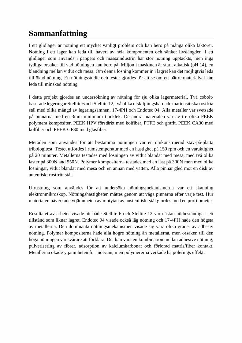
Dry sliding of PEEK against stainless steel surface has a higher coefficient of friction in the
beginning before it reaches the steady-state. With the same material surface but in water-
lubricated the friction was very low in the beginning but increased until it reaches the steady-
state, see Figure 14 [21].
Figure 14: Friction coefficient of PEEK reinforced with carbon fiber and PTFE sliding against stainless steel under dry
sliding and water-lubricated conditions.
Friction coefficient is lowered when a higher load is applied, this is believed to be connected to
the thermal and mechanical effects introduced at higher loads, which generate a softer matrix
and decrease the polymers shearing strength. A higher velocity during water-lubricated
condition decreases the wear-rate significantly, which is said to be addicted to the fact that it is
easier to get a complete water boundary lubrication [21].
1.4.2 Corrosion of Carbon Fiber
It has been showed that when carbon fiber is in contact with steel or aluminum the pairing is
exposed to galvanic corrosion, this because of the differences in electrochemical potential
between the metals and carbon fiber. With an electrolyte media present the fiber reinforced
Page 29
19
composite is acted as an anode and the steel counter face as a cathode, which lead to a galvanic
corrosion [27].
PEEK that is reinforced with short carbon fiber used in journal bearings with aqueous media
present between the sliding surfaces, has showed early failure that has been connected to the
galvanic corrosion of the carbon fibers. PEEK that contained a carbon fiber content of 10%
showed no corrosion at all of the different environment. For a 30% carbon fiber PEEK the fiber
corrosion occurred with all electrolyte solutions. The test was done with electrolytes like tap
water, sodium carbonate and sodium nitrate solutions [27].
The corrosion enhances two specific mechanisms that can lead to failure, the loss of adhesion
between the fiber and matrix area and also cracking of the carbon fiber. Corrosion resistance
has shown to be different for different carbon fiber, a polyacrylnitrile based fibers have shown
to have better corrosion resistance compared to pitch based [27].
1.4.3 Polymers in alkaline environment
Some polymers are seemed to be affected badly in an alkaline environment. This is related to
that some polymer undergoes a hydrolysis in an alkaline environment. Polyester film that was
exposed to alkaline solution of sodium hydroxide showed mass loss, which could be explained
by the hydrolysis process. Pitting was found at the sample surfaces and with the increasing
exposed time the depth, lateral size and volume of pits increased. The pitted area at the polymer
contained much more dark-colored areas, which was believed to be due to water insoluble
degradation products [28].
In experimental analysis of polyester resin immersed in sodium hydroxide (NaOH), it was
detected a penetration of NaOH into the polymer. Like in other tests the surface become darker
[29]. Flourelastomers are often used as gasket, seals and O-rings, but an alkaline environment
has been found to have a bad effect to this type of polymer. After a few weeks, tiny cracks
appear on the surfaces of the elastomer and the depth of these cracks increased with the testing
time. Mechanical properties like tensile strength and elongation at break seemed to be decrease
with longer exposure time [30]. PEEK on the other hand, has increased in use due to its
hydrolysis resistance [31].
1.5 Parameters affecting wear in sliding bearing
1.5.1 Misalignment
Misalignment in a journal sliding bearing is a main problem and can have considerable effect
on the performance. It causes wear, vibration and can lead to total failure of the construction.
Wear of a bearing is commonly caused by misalignment of the axel shaft [32].
The width of the bushing and the length of the axel has great influences of different situations
that may occur during use. A too small width of the bushing can cause high edge pressure of
the bushing due to misalignment of the axel, Figure 15 left. To avoid these large edge loads the
Page 30
20
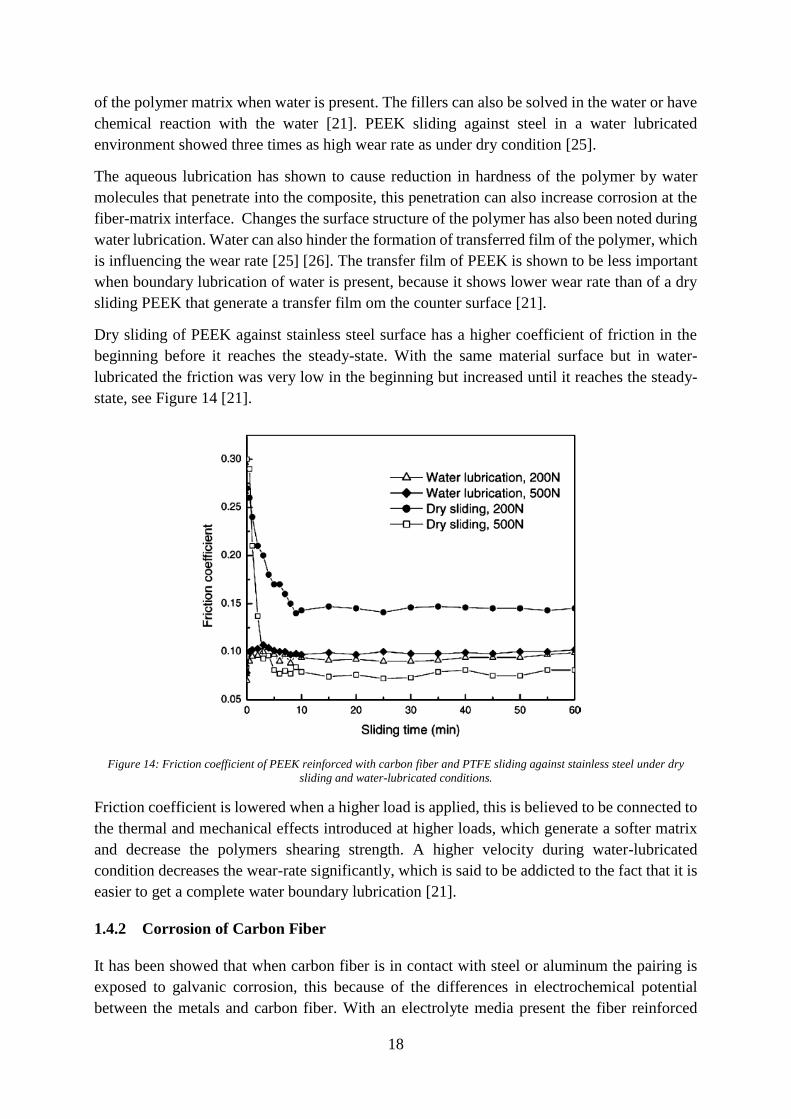
width to diameter ratio should be taken into account. For a long bushing there is less chance of
misalignment. Instead problems with bending of the axel could be a problem if the axel isn’t
stiff enough for the applied load, Figure 15 right [9]. The temperature can also increase
significantly and get more severe when the bearing is misaligned. Simulation results has shown
that misaligned bearing influence pressure, temperature and cavitation [32].
Figure 15: Loading distribution due to misalignment (left) and bending (right).
The bearing housing also plays an important role to withstand mechanical deformation, high
load contacts and wear. A housing construction with to low stiffness generate thermal and
mechanical deformations to the bearing, which can lead to misalignment. But a high stiffness
housing doesn’t allow conformal deformations which can prevent high edge loadings. The
housing stiffness effects the pressure distribution in the bearing, which is important to avoid
wear [9].
1.5.2 Grooves
Grooves in a journal bearing has shown to have major impact on the performance. The grooves
can be of different design, shape and can be applied either in the bushing or in the axel. Grooves
decreases the loading capacity of a bearing, which gives higher contact pressure. Researchers
have found that changes in the shape and lead of the groove can lead to two-times decrease in
wear of the journal bearing in comparison to a plain journal bearing. But it can also help to
decrease the temperature, remove abrasive particles and get a more even temperature in the
bearing, by adding a cooling liquid that flow through the grooves. It can also prevent the
formation of cavitation in the bearing [33].
1.5.3 Materials
Metallic bearing can carry very high loads but has high coefficient of friction (COF) and
lubrication is often a requirement to withstand wear. The lubrications of the metallic bearing
are sometimes not possible and often expensive. Polymer-based composite bearings in
comparison to metals have much lower COF and is self-lubricated but can’t withstand high
loads. The fiber reinforcement increases mechanical properties that makes them more useful in
higher load situations. Because of polymers corrosion resistance they can also be applied to wet
or wet-dry conditions. Polymer composite bearing has also shown to have good properties to
Page 31
21
withstand high edge pressure that occur at misalignment of sliding bearing. Some polymer like
phenolic has shown to work static factorily in combination with a steel axel in a sliding bearing,
which might lower the wear affected by high load in misalignment. [34]
1.5.4 Temperature
The heat that is generated in the bushing is affected by the frictional force and the sliding speed.
The biggest part of the generated heat will enter the material with the highest thermal
conductivity. It is important to know the temperature in the bearing, because the heat expansion
of the axel and bushing might be of the same range of the manufacturing tolerance and bearing
play. The shrinking and expansion of the axel and bushing can be calculated according to
equation (7).
∆𝑑 = 𝑑 ∙ 𝛼 ∙ ∆𝑇
(7)
Where 𝛼 is the thermal expansion coefficient for the material in the axel or bushing, ∆𝑇 is the
temperature increase and d is the diameter of the axel or bushing. Metals are better material for
thermal transportation and can withstand higher temperature than polymer composites. [9]
The maximum temperature in an aligned bearing is in the mid-plane compared to a misaligned
bearing the maximum temperature is removed from the mid-plane. The temperature is much
higher in a misaligned bearing than in an aligned one. [32]
1.6 Material study
For metals the deformation of the asperities will be of plastic character and in tribology the
yield pressure for plastic deformation is assumed to be close to the indentation hardness. Which
lead to that metals with higher hardness is often harder to deform the asperities and have lower
wear rate. To withstand the shear stresses introduced in the surface during sliding which can
cause cracking, a good fracture toughness and a high yield strength might also lower the wear.
Material groups with high combination between hardness, yield strength and fracture
toughness, Figure 16 and Figure 17. The materials microstructure is also influencing the wear
and it is hard to predict the wear by just looking at material properties. Wear is complex and
influences of several factors. [6]
Page 32
22
Figure 16: Material with high combination between hardness and fracture toughness.
Figure 17: Materials with high combination of yield strength and hardness.
Nickel-, iron- and Cobalt-based alloys have a great combination between a high hardness,
fracture toughness and yield strength. These materials were therefore studied more in detail and
how they get their unique properties.
1.6.1 Cobalt alloys
Cobalt has a hexagonal close-packed (hcp) structure (휀-cobalt), but at higher temperature about
~415℃ and its melting point 1493 ℃ it exhibits a face-centered (fcc) structure (𝛼-cobalt). The
alloying element in the structure has main influences of these temperatures. Chromium,
Page 33
23
tungsten, and molybdenum are HCP-stabilizer, Iron and Nickel are FCC-stabilizer. Cobalt
alloys are often categorized in three different groups [35]:
• High-carbon alloys for wear service
• Low-carbon alloys for high-temperature service
• Low-carbon alloys to combat corrosion or simultaneous corrosion and wear
The primary strengthening mechanism of the cobalt alloys is carbides and the second
strengthening mechanisms are in form of solid-solution of chromium, tungsten and
molybdenum. [36] These alloys exhibit superior wear resistance and corrosion resistance, and
cobalt is one of the hardest material known. The good properties are believed to be achieved by
the crystallographic nature of cobalt, carbides and solid-solution strengthening. [37]
Stellite alloys are often used in casting form or weld overlays (hardfacing alloys). The alloying
element tungsten and carbon are characterizing the properties of Stellite 6 and 12. Chromium-
rich M7C3 carbides are the main present carbides in the Co-Cr-W based alloys, with high
amount of tungsten also tungsten-rich M6C carbides could be present. [35]
Stellite is mostly used in high temperature wear applications. The carbides in combination to
the tough and ductile matrix of cobalt make them resistance to oxidation and withstand wear of
plastic deformation and fatigue. Experimental studies of sliding wear of different Stellite has
shown to decrease with increasing carbon content. The carbon content determines the amount
of carbides, which is main strengthening mechanism against sliding wear of cobalt-base alloys.
The Stellite alloys are seemed as almost wear resistance in some situations. [38]
1.6.2 PEEK Composite
Poly-ether-ether-ketone (PEEK) is a semi-crystalline thermoplastic polymer and belong to the
polyaryletherketone (PAEK) family. It has a chemical structure that consists of para linked
phenyl and benzophenone units that can be seen in Figure 18. [39][40] Due to its structure and
crystallinity, PEEK has excellent mechanical properties and thermooxidative stability. PEEK
has a high glass transition temperature at 𝑇𝑔 = 144 ℃ and a melting temperature at 𝑇𝑚 =
343℃ . [40][41] PEEK is also chemical inert and biocompatible. [41]
Figure 18: Chemical structure of PEEK.
The most PEEK material that is used in tribological application is filled with e.g. carbon fibers,
glass fibers and/or aramid fillers, this hard-reinforcing material increase the loading-capacity
of the polymer matrix and the abrasion resistance. [41][19]
Page 34
24
1.6.3 Stainless Steel
Stainless steel has iron as a base material and it contains of a minimum 11% Cr. [35] Cr is
added to the material to achieve their stainless characterization through the formation of an
invisible and adherent chromium rich oxide passive film. [42] The stainless steels are often
divided into five different groups:
• Austenitic stainless steels
• Ferritic stainless steels
• Martensitic stainless steels
• Duplex stainless steels
• Precipitation-hardening stainless steels
The largest group of the stainless steels is the austenitic stainless steels. By adding amounts of
Ni, Mn, C and N into iron the face-centered crystal structure, austenite (𝛾) is stabilized at room
temperature. Duplex stainless steel (DSS) consists of two different phases, ferrite (𝛼), a bcc
crystal structure of Iron and austenite (𝛾). The two phases consist of at least 11wt% Cr. The
DDS generally chemical composition is of 17 to 30wt% Cr and 3 to 13wt% Ni, and some other
added alloys. [43]
Chromium and Nickel are mostly added to achieve stabilization of the austenitic structure at
room temperature. Nickel also increases fabrication characteristic and the mechanical
properties. By adding Molybdenum and nitrogen there will be an increase in strength and there
will be enhanced stabilization of the passive film when chlorides are present, which increase
the resistance to general corrosion and pitting corrosion. Carbon composition is often low, but
give some strengthening effect. [42]
The precipitation hardening stainless steels (PHSSs) are often divided into three different
classes, austenitic, martensitic, semi-austenitic and a newer developed grade of duplex. The
strength of this material is obtained from the formation of the martensitic phase and from the
precipitation-hardening. [42]
Martensitic Age Hardening Stainless Steels are usually solution-treated at a temperature range
of 815-900℃ and then quenched, which produces a bcc martensite matrix. Then the material is
aged at a temperature between 400-600℃. [44] The bcc martensite is softer and more ductile
than the BCT martensite that has few slip planes. Precipitation-hardening, also called age
hardening involves a type of phase transformation. This transformation leads to formation of
uniform dispersion of nanoscale, coherent precipitates in a softer and more ductile matrix.
These precipitates act as an obstacle to the dislocation movement and increase the strength of
the material without further change in density. [43] Materials like 17-4PH, 15-5PH, 16-4Mo,
PH 13-8 Mo belongs to this type of material. [44]
Martensitic stainless steel contains of less chromium and higher carbon than the other stainless
steel, this to be able to obtain the austenitic phase at higher temperature and then by fast cooling
transform the austenite to martensite. The content of chromium is limited because of the
stabilization of the ferritic phase. [35] The materials have good combination between the
ductility and a high mechanical strength. [44]
Page 35
25
Cobalt is an austenite stabilizer in steels. Addition of Cobalt in Cr-steels has seen to increase
the control of 𝛿 ferrite and doesn’t suppress the martensite start temperature as other alloying
elements. Nickel and cobalt are often added to the martensitic steels to make it completely
martensitic and also increasing the toughness and strength. [45]
Martensitic stainless steel contains carbides that can generate hard wear debris that will acts as
an abrasive wear particle. The steel can also contain residual stresses from the heat treatment
that generate cracks during sliding, which leads to the delamination theory. The wear resistance
of the martensitic stainless steel is seemed to be depend on the retained austenite but also the
carbide content. When the retained austenite become stress-introduced into martensite the wear
resistance seemed to increase. Carbides on the other hand has seemed to increase the wear when
they go extracted, and that was a main factor when the load was increased. In lab tribology
studies around the material 17-4PH the main wear mechanisms has shown to be micro-grooving
adhesion and micro-delamination. To minimize the wear of a martensitic stainless steel, the
plasma nitriding has shown to be a very good choice. [44]
1.6.4 Nickel-based-superalloys
Nickel-based superalloy consist of mainly face-centered crystal structure nickel and about 40wt
% of five to ten other alloying elements. The main strengthening mechanisms of nickel-based
super alloys are solid-solution strengthening, precipitation hardening and dispersion
strengthening. But also grain size refinement can also be counted as a strengthening mechanism.
The strengthening precipitates in Ni-base superalloy are formed by adding element as titanium,
aluminum and niobium. Which leads to formation of coherent precipitates gamma prime, 𝛾′,
Ni3(Al,Ti), and 𝛾′′, Ni3Nb. The gamma prime phase has an ordered intermetallic L12 crystal
structure. [46] [47]
Nickel-based-superalloys are usually divided into different group based on alloying element.
Some of them are Nickel-chromium-iron, Nickel-chromium-molybdenum, Nickel-chromium-
iron-molybdenum and precipitation-hardening alloys. These alloys have high heat and
corrosion resistance. They often contain alloying of 15-30% chromium, which increases the
resistance to oxidation media. Molybdenum is improving the resistance to corrosion in form of
pitting and crevice corrosion. [35]
1.6.5 Iron-based superalloys
Iron-based superalloys have been developed from the austenitic stainless steel and have a fcc
crystal structure matrix. This alloy is often strengthened by the solid-solution hardening and
precipitation hardening. It contains at least 25% Ni to stabilize the FCC phase and also other
alloying element such as chromium, which contribute to the solid-solution hardening. From the
precipitation strengthening intermetallic phases like 𝛾′ Ni3Al, 𝜂 Ni3Ti and 𝛾′′ Ni3Nb are
formed. [48]
Incoloy 925 and A-286 is precipitation hardened alloys of Iron-Nickel-based superalloy. That
contains mainly of iron, nickel and chromium. But also smaller amount of Aluminium and
Titanium to get strength of the precipitates.
Page 36
26
1.7 Aims and purpose
The purpose of this study is to obtain the most suitable combination of the sliding material for
the bearing with regard to the tribological factors, parameters and the environment.
The aims of this study are:
• Compare the different bushing material in wear rate.
• Obtain the wear mechanisms for the different bushing materials.
• Find possible replacement material to Cobalt-base material.
• Investigate the difference in wear for metals with higher loads.
• Investigate the meaning of different liquid solution present at polymer composites.
• Obtain how different material is affecting the countersurface.
Page 37
27
2 Method and Material
To evaluate the wear rate, wear mechanisms and how the different materials are affecting the
countersurface, a pin-on-disc wear test was constructed. The wear was measured by weighted
the pin material before and after each test. Seven different bearing materials were tested towards
one axel material. The test materials were a mix of different metals and polymer composites.
To investigate the worn surfaces a scanning electron microscope and a profilometer were used.
2.1 Test Material
Figure 19: An overview picture of the different in hardness and fracture toughness of the test materials.
Seven different pin materials were used in the tribology test, which should represent the bearing
material of the sliding bearing. Four different metal materials, Stellite 6, Stellite 12, Endotec 04
and 17-4PH. Endotec 04 is a coating of martensitic stainless steel with precipitation hardening
structure, with high amount of Cr and Cobalt alloying. Stellite 6 and Stellite 12 is cobalt-base
materials with high amount of Cr. 17-4PH is a precipitation hardening martensitic stainless
steel. The other three test materials were PEEK HPV, PEEK GF30 and PEEK CA30, which is
polymer composites reinforced with different amount of fillers. A comparison between the
hardness and fracture toughness of some of the used material during the test is represent in
Figure 19.
The disc material was representing the axel material of the bearing and today that is of 1.4462
duplex stainless steel. In the test a 1.4301 austenitic stainless steel was used, the chemical
composition, see Table 2. The different chemical composition of the used metals can be seen
in Table 2. The different polymer composite material and its fillers content in Table 3.
Page 38
28
Table 2: Chemical composition of all the metal materials [49-54] [49] [50] [51] [52] [53] [54]
Table 3: Filler composition of the polymer composites used for the tests [55]
In Table 4 material properties for the materials used during the test and 1.4462 which is used
as a disc material in the real bearing. The hardness for a polymer is given in Rockwell-M scale
and the metals in Rockwell-C scale. For some polymer the yield strength was not applicable
and some of Endotec 04 material properties was not available.
Table 4: Mechanical properties of all the different material [49-56] [56]
2.2 Execution of Test
2.2.1 Construction of the wear test
An old grinding machine, ABRAMIN, was reconstructed to a pin-on-disc tribology test, see
Figure 20. A new grinding plate was designed, which function was to hold the disc during the
test and after each test the disc was replaced with a new one. The constructed grinding plate
was designed with a higher edge so the added slurry solution should stay on the plate easier.
On this plate a thin disc of 2 mm thickness was placed and fixed by six M6 set screws, the
dimensions and construction of the plate, pin and disc are shown in appendix A.
Cr C W Si Mo Mn Ni Fe Co Cu P S Nb + Ta N
Stellite 6 27.95 1.10 5 1.05 0.05 0.95 0.15 3.90 base
Stellite 12 29 1.6 8.5 1.5 0.3 ≤3 ≤2.5 base
Endotec 04 12.19 0.16 0.57 2.85 0.16 base 12.95 0.01
17-4PH 15-17.5 0.07 1 1 4-5 base 4-5 0.04 0.03 0.15-0.45
1.4462 22 0.02 3.1 5.7 base
1.4301 17.5-19.5 ≤0.07 ≤1 ≤2 8-10.5 base ≤0.11
Carbon fiber (%) Glass fiber (%) Grafit (%) PTFE (%)
PEEK HPV 10 10 10
PEEK GF30 30
PEEK CA30 30
Hardness (Rockwell) E-modulus (GPa) Yield strength (MPa) Density (g/cm3)
PEEK GF30 M100 7.0 80 1.51
PEEK HPV M85 5.9 NA 1.45
PEEK CA30 M100 9.2 NA 1.4
17-4PH C35 197 758 7.78
Stellite 6 C42 209-237 700-750 8.44
Stellite 12 C50 208-226 580-900 8.53
Endotec 04 C50
1.4462 C25 200 460 7.8
1.4301 C19 200 190 7.9
Page 39
29
Figure 20: The grinding machine that was reconstructed to a pin-on-disc tribology test.
The pins were placed in the pin-holder and the machine pushed down the pins with an applied
force, se Figure 21. Three pins were used for each test to get a better stability and reduce the
risk of misalignment when the pin-holder was pushed down. The disc and the pin-holder rotated
with a given velocity of rpm. The liquid solution was added manually during the whole test
period.
Figure 21: Illustration of how the pin-on-disc wear test is working.
Page 40
30
2.2.2 Wear Test conditions
Three different wear tests condition were performed with the pin-on-disc test.
Test conditions A:
• Sliding speed 150 rpm
• Load 300 N
• Pressure at the pins: 1N/mm3
• Duration 20 min
• Added liquid: White liquor and lime mud
Test condition B:
• Sliding speed 150rpm
• Load 550 N
• Duration 20 min
• Added liquid: White liquor and lime mud
Test condition C:
• Sliding speed 150rpm
• Load 300 N
• Duration 20 min
• Added liquid: water
2.3 Investigation of Wear
2.3.1 Wear rate
To evaluate the mass loss in form of wear the pin material was weighted before and after each
test. The used weighing machine was a Sartorious Basic, Figure 22.
Figure 22: The used weighing machine Sartorious Basic.
Page 41
31
2.3.2 Scanning Electron Microscope
To investigate the worn surfaces of the pins, a LEO 1530 scanning Electron Microscope (SEM)
was used, which can be seen in Figure 23. The wear track was investigated perpendicular to the
surface to establish wear modes and wear mechanisms.
An Energy Dispersive Spectroscopy (EDS) was used to investigate the chemical composition
of different areas at the surface. For the non-electrically conductive polymer composite, a gold
coating was applied on the surface before they could be used in the scanning electron
microscope.
Figure 23: The used Scanning Electron Microscope and the Energy Dispersive Spectroscopy to evaluate the wear
mechanisms.
Page 42
32
2.3.3 Profilometer
To evaluate the topography of the worn countersurface an Contour GT-K 3D optical
Microscope with software Vision 64 shortcut was used, can be seen in Figure 24. The
topography of the surfaces could be seen both in 2D and 3D.
Figure 24: The used Contour GT-K 3D optical Microscope.
Page 43
33
3 Results
3.1 Wear
With the pin-on-disc tribology test the wear rate of the seven different bushing materials under
different conditions was investigated and compared. With the scanning electron microscope,
the possible wear mechanism present at the worn surface was investigated.
3.1.1 Wear rate
Figure 25 shows the mass loss with respect to time of the pin materials from the pin-on-disc
tribology test, with test condition A. PEEK GF30 showed to have the highest wear rate and
Stellite 6 and 12 the lowest. All the polymers had higher wear rate than all the metals.
Figure 25: Mass loss with respect to time during the pin on disc test for all the seven bushing materials, in test condition A.
In condition B the metals were tested with a higher load. The mass loss with respect to sliding
time is represented in Figure 26. Only 17-4PH showed to be affected in wear loss when the load
was increased. The other metals still showed no mass loss in form of wear. Figure 27 indicated
the mass loss of the polymer with different liquid added between the surfaces during the pin-
on-disc test. Clear wear was seen when the liquid slurry of white liquor and lime mud was
added. No wear was indicated for PEEK CA30 and PEEK HPV when water was added between
the surfaces.
Page 44
34
Figure 26: Mass loss with respect to time during the pin-on-disc test for the metals, with different loads.
Figure 27: Mass loss with respect to time during the pin-on-disc test for the polymer composites, with different liquid present
during the test.
Page 45
35
In Table 5 the wear coefficient of the different pin materials in different test conditions are
present. Worth mentioned is that Endotec 04, Stellite 6 and Stellite 12 wear coefficient can be
seen as almost zero. Because that small weight can be affected by the wind and oxygen in the
room, the used weighing equipment do not has such as high accuracy. The polymers wear
coefficient during the condition C, is also very small and can be seen as almost zero, because
no clear wear loss could be detected on the pin surface.
Table 5: Wear coefficient of the pin material in different test conditions
Wear coefficient k (10 -5 ∙g/min) Condition A Condition B Condition C
Endotec 04 4.63 1.33
Stellite 6 1.53 2.80
Stellite 12 1.40 0
17-4PH 16.51 200
PEEK HPV 31.00 4.8
PEEK GF30 75.13 9.5
PEEK CA30 44.40 1.3
Page 46
36
3.1.2 Evaluation of wear mechanisms of pin material in SEM
With the scanning electron microscope, the wear mechanisms present at the surface of the
materials was investigated. The precipitation martensitic stainless steel 17-4PH which showed
highest wear rate of the metals during the test showed clear adhesive wear mechanisms, Figure
28. In Figure 28 a) an overviewed how the wear mechanisms are changing the morphology of
the surface. Figure 28 b) is a closer picture of the adhesive wear with clear plastic deformation
and cladding of the asperities. The direction of the adhesive wear is various because of the
rotation of both the pins and disc during the test. Figure 28 c) shows how the plastic deformation
generated from the shear stress during sliding has led to detachment of wear debris.
a) b)
c)
Figure 28: SEM picture of the worn surfaces of 17-4PH in 300N load a) transition of adhesive worn and unworn area b)
closer picture of the adhesion c) adhesion transfer particle.
Page 47
37
Increasing of the load in the wear test lead to a larger worn area for 17-4PH, which can be seen
in Figure 29 a). Adhesive wear is still the dominated wear mechanisms but more severe rapture
and detachment of wear debris could be seen, Figure 29 b).
a) b)
Figure 29: SEM picture of the worn surface of 17-4PH with load of 550N a) adhesive worn surface overview b) closer
picture of the adhesive wear mechanism.
Endotec 04 showed no wear loss during the test and no detachment of material could be seen at
the SEM analysis. The dominated wear mechanisms for Endotec 04 was adhesive wear in form
of some plastic deformation of the material, Figure 30 a). The only thing that was changed with
higher load, was the size of the worn area, but the wear mechanism was the same, Figure 30 b).
In Endotec a lot of porosity could be detected, an EDS analysis of the porosity, see Appendix
B, this may be due to a poor welding.
a) b)
Figure 30: SEM picture of the worn surface of Endotec 04 a) 300N b) 600N.
Page 48
38
Stellite 6 also showed a dominated adhesive wear mechanism in form of plastic deformation, a
lot of material cladding was shown, Figure 31 a). The scars come from the grinding process
which was done before the wear test. The same mechanisms were dominated at the surface with
higher load, Figure 31 b).
a) b)
Figure 31: SEM picture of Stellite 6 adhesive worn surface with different load a) 300N b) 550N.
Less plastic deformation was shown to be present at Stellite 12 surface Figure 32 a). The surface
looked more like it has been polished. But some differences could be seen by comparing the
different load situations Figure 32 a) and b), more adhesive wear in form of plastic deformation
was detected when a higher load was applied.
a) b)
Figure 32: SEM picture of the worn surface of Stellite 12 with load of a) 300N b) 550N.
Page 49
39
Another thing that was detected during the analysis was that the slurry of white liquid and lime
mud has shown to adhere to the Stellite 12 surface, Figure 33, in both of the load situations.
This could also be seen at Endotec 04 surface, the slurry seemed to adhere to the surface or
stick to uneven places at the surface, Figure 34. An EDS analysis of the contamination was
done and it contained a lot of calcium, which comes from the lime mud, see Appendix B.
Figure 33: SEM picture of Stellite 12 surface where the slurry with white liquor and lime mud has adhere to the surface.
Figure 34: SEM picture of Endotec 04 surface and the slurry that has adhere to the surface.
Page 50
40
Wear of the polymer composite could also be detected with the scanning electron microscope.
Only the worn polymer composite in the liquid slurry of white liquor and lime mud was
investigated because the present of water showed no clear worn surface.
PEEK HPV that contains carbon fiber, PTFE and graphite fillers showed a shear deformed
polymer matrix with multiple clear holes in the polymer, but the clear wear mechanism of the
polymer matrix was hard to see. Fiber/matrix separation was believed to be seen. The area that
has a lighter form of grey, that looks like powder could be a mix between pulverization of the
carbon fiber and attachment of calcium carbonate (lime mud), Figure 35. Some scratch mark
could be seen in Figure 35 c).
a) b)
c)
Figure 35: SEM picture of PEEK HPV a) worn surface b) closer picture of the crack at the interface area between carbon
fiber and the polymer matrix.
Page 51
41
Clearer adhesive wear of the polymer matrix could be detected for PEEK CA30, Figure 36 a)
and b). Some scratch mark could be seen in Figure 36 a), which can be caused by debris of
carbon fiber that has act as an abrasive particle. Cracks and fiber-matrix separation could be
detected in this polymer composite too, Figure 36 b) and c), but not as much as in the PEEK
HPV. In the same manner as PEEK HPV the light grey powder could be a mixture of
pulverization of carbon fiber or attachment of calcium carbonate.
a) b)
c)
Figure 36: SEM picture of PEEK CA30 a) overview of worn surface b) clearer picture of the adhesive wear c) adhesive wear
and fiber separation.
The largest worn polymer matrix could be seen at PEEK GF30 surface, in form of adhesive
wear. The polymer matrix has been large plastic deformed, the top surface layer has been
smeared out and further transformed due to the sliding, Figure 37. Some of the adhesive formed
wear looked like rolling formation, which is a common form of wear mechanism for elastomers.
Much larger cracks could be detected in the glass fiber of the PEEK GF30, Figure 37 c).
Page 52
42
Pulverization of the glass fiber could be a possible wear process or calcium carbonate that was
stuck on the surface.
a) b)
c)
Figure 37: SEM picture of PEEK GF30 a) overview of worn surface b) clearer picture of the adhesive wear c) fiber crack
formation.
Some of the lighter powder at the surface of the different PEEK composites could be wear
powder from the steel countersurface too. Because the polymer had a polishing effect on the
countersurface at the wear test.
3.2 Investigation of Worn Countersurface
How the disc countersurface roughness and topography was affected by the different pin
material was investigated with the profilometer. The difference in the average roughness Ra for
the 1.4301 austenitic stainless-steel disc sliding against four different pin metals Endotec 04,
Stellite 6, Stellite 12 and 17-4PH is presented in Table 6. In Table 6 it can also be seen how the
Page 53
43
average roughness is changed when a bigger load is applied. Notable is the change of average
roughness when sliding against Stellite 12 and Endotec 04.
Table 6: Average roughness parameter for the disc of 1.4301 austenitic stainless-steel sliding against different metals with
different applied load
In Figure 38 and Figure 39, the average roughness curves for the discs sliding against several
metal materials with different load. Worth mentioning is the difference in wear depth of the
disc surface sliding against Stellite 6 and Stellite 12 with different loads. Endotec 04 doesn’t
showed any deeper wear depth as Stellite 6 and Stellite 12 when the load was increased, but an
increase in average roughness. Stellite 6 has less wear depth than Stellite 12 at higher loads.
Figure 38: Average roughness curves for the disc surface sliding against iron-based metals 17-4PH and Endotec 04, at
different loads.
Figure 39: Average roughness curves for the disc surface sliding against cobalt-based metals Stellite 6 and Stellite 12, at
different loads.
Load 300N 550N
Average roughness Ra (μm) Ra (μm)
Endotec 04 1.546 2.029
Stellite 6 1.824 1.537
Stellite 12 1.293 2.046
17-4PH 1.818 1.89
Page 54
44
By looking at 3D picture, of the worn disc surfaces sliding against Endotec 04 at different loads,
Figure 40, a clear change of the surface could be seen. A much more uneven surface could be
detected, with clearer wear scars. The picture of the deeper wear depth of the disc surface sliding
against Stellite 12 could be seen by looking at the 3D picture in Figure 41.
Figure 40: 3D picture of surface roughness of disc sliding against pin Endotec 04 a) 300N b) 550N.
Page 55
45
Figure 41: 3D picture of surface roughness of disc sliding against pin Stellite 12 a) 300N b) 550N.
The difference in the average roughness Ra for the 1.4301 austenitic stainless-steel sliding
against three different polymer composites PEEK HPV, PEEK GF30 and PEEK CA30 are
presented in Table 7. Notable is that no clear changes of the roughness could be seen for
different liquid present between the surfaces.
Table 7: Average roughness parameter for the disc of 1.4301 austenitic stainless-steel sliding against PEEK polymer
composites with different added liquid
By looking at the average roughness picture in Figure 42, a clear difference of the average
roughness could be seen compared to metal-metal worn surfaces. The 3D picture of the disc
sliding against different polymer composite has a very smooth surface, the polymer sliding
against a steel disc had more of a polishing effect, Figure 43.
Added liquid white liquor & mesa water
Average roughness Ra (μm) Ra (μm)
PEEK HPV 0.366 0.367
PEEK GF30 0.301 0.26
PEEK CA30 0.318 0.316
Page 56
46
Figure 42: Average roughness curves for the disc surface sliding against three different PEEK composites with liquid
solution of white liquor and lime mud present.
Figure 43: 3D picture of surface roughness of the disc sliding against pin a) PEEK HPV b) PEEK CA30 and c) PEEK GF3.
Page 57
47
4 Discussion
4.1 Wear
4.1.1 Metals
All metals showed adhesive wear mechanisms which is dominated in sliding situation. The
added liquid slurry of white liquid and lime mud showed no evidence of abrasive wear at the
surface. Which was a hypothesis that might happened in the sliding bearing during use.
According to Figure 25 the cobalt-based material Stellite 6 and Stellite 12 was the ones with
lowest wear loss per sliding distance. The SEM picture Figure 31 and Figure 32 showed clear
evidence of adhesive wear of the surface, but no wear loss in form of detachment of wear debris.
Stellite 6 showed more apparent plastic flow of the asperities, compared to Stellite 12 where
the area seemed to be more polished. That can be related to the difference in hardness and
carbon content. Higher hardness decreases the wear loss according to Archard equations and
the carbon content seems to increase the sliding wear resistance for Stellite alloys, according to
Falqueto LE et al [38]. This result was a fairly predictable result, because of the cobalt-base hcp
structure, high hardness and strengthening mechanisms they are sometimes seemed as almost
wear resistance.
When the load was increased the wear mechanism was still the same for both of the cobalt-
based alloys and the wear coefficient was still very low, Table 5. But a larger worn area was
detected at the pin surface. A higher load might not always lead to more wear in form of mass
loss. Because when the load is increasing more asperities get in contact and the real area of
contact become bigger, which makes the load spread on a larger area.
Endotec 04 also showed very low wear coefficient compared to 17-4PH, Figure 25, which also
is a precipitation hardened martensitic stainless steel. That can be related to the differences in
microstructure affected by the amount of alloying element. Endotec 04 has a much higher
amount of cobalt alloying in the structure. According to Davis JR [31] higher amount of cobalt
increases the volume of the advantageous secondary precipitates in iron. The precipitates [43]
acts as an obstacle to further movement of the dislocation and strengthen the material in form
of preventing plastic deformation. Stachowiak [4] said that plastic deformation has to be present
if material loss of adhesive wear will be a factor. Cobalt also increase the strength and toughness
of the iron matrix which might affect the wear rate.
The wear mechanism of Endotec 04 was adhesive wear in form of plastic deformation of the
asperities, Figure 30 a). It also looks like there has been some rapture of grains when the load
was increased, in Figure 30 b) and a lot of porosity was found at the surface with higher load.
Which may be due to a poor welding and that may increase wear, pores can act as a crack
initiation.
17-4PH had the highest wear rate and a dominated adhesive wear mechanism at the surface and
wear debris loss was found. Much more severe wear was present at the sliding surface when
the load was increased, Figure 29. The adhesive contact bridges are broken by shear fracture of
Page 58
48
the material and they leave the material as wear debris. Other studies [44] have shown that
carbides in a martensitic stainless steel increased the wear coefficient when the load was
increased. That might be a factor in this case to.
Hutchings et al [6] confirmed that two more similar material are much more adherent to each
other than two dissimilar materials. Which can be another explanation to the much higher wear
of the 17-4PH material compared to the other three that has much more dissimilar structure and
alloying element than the disc material of austenitic stainless steel, which will affect the wear
rate.
Stachowiak [4] also showed that lower adhesive forces are formed for a hcp structure and it is
harder to get plastic deformation because of the less slip-plane. By comparing the fcc structure
(17-4PH and Endotec 04) and the hcp structure (Stellite 6 and Stellite 12) this showed to be
true, whit the exception of Endotec that contains a lot of cobalt alloying and has a much higher
hardness than 17-4PH with the same crystal structure. But Hutching et al [6] also said that
sometime the adhesive forces are not necessary to remove material, in this case it depends
mainly on the mechanical interaction of the asperities.
At Stellite 12 the solution of white liquid and lime mud could be seen to be cladded on the
surface Figure 33. This observation was found at Endotec 04 surface too, Figure 34, and
according to an EDS analysis in appendix B, the material contained a lot of calcium. According
to Wang H [57] strong adsorption of calcium carbonate on stainless steel can be observed.
No clear evidence of corrosion was found on either of the surfaces, but the pin was only in
contact with the slurry for 20 min and corrosion takes time. According to Efremenko VG et al.
[16] martensitic stainless steel showed clear evidence of pitting sites, even at pH of 7. It also
showed according to Salasi M et al. [18] when the temperature was increased the corrosion
density increased too. That might be a factor if a corrosive media is present between the surface
for long time and affect the oxide layer badly. Which might lead to corrosive wear and enhance
some of the mechanisms present in Figure 8. Martensitic stainless steel may not be
recommended to be used in strong alkaline environment because of it limitation in Cr content.
4.1.2 Polymer composite
The investigation of the polymer composites was harder to give a clearer cause to the wear, it
can depend of several different factors. No similarly wear test with alkaline environment present
at PEEK polymer composites was found in the theory, therefore the polymer composites were
also tested with water present, to see how the alkaline solution affected the wear.
The test with water present showed no clear wear of the polymer composites and the wear
coefficient in Table 5 was very low. Gebhard A et al [25] confirmed that several experimental
analysis has indicated that this reduction in wear is believed to be incident to formation of a
water lubrication film at high sliding speed and with the combination of cooling by the water.
In the real situation the bearing has a much lower sliding velocity and a formation of a
lubrication film is not possible.
Page 59
49
But with the water present the countersurface seemed to be polished but the wear of the polymer
pin was not detected. So, from this it can be assumed that not a full film lubrication was formed,
the surfaces are still in some contact and present of the liquid solution of white liquor and lime
mud seems to increase the wear of the polymer composites, Figure 27.
At the worn surface of PEEK HPV, Figure 35, matrix/fiber interfacial removal was shown and
obvious hole in the polymer matrix was detected, Figure 44. According to Jia J et al [21] the
matrix/fiber interfacial removal could be caused by the swelling of the polymer matrix, which
was seemed to be present with water. This might also be a factor when the solution consists of
white liquor and lime mud.
Figure 44: Clear picture of holes that was detected in the PEEK HPV matrix.
By comparing the different SEM picture of the three PEEK composite, clear difference severity
of the wear could be detected at the polymer matrix. It was hard to say what wear mechanism
that caused the wear of the polymer matrix of HPV, at the test it was seemed that the matrix has
been worn in and shear deformed. HPV showed the lowest wear loss with the solution of white
liquor and lime mud present, according to Table 5. The less wear of the PEEK HPV polymer
matrix could be related to the fillers of PTFE and graphite which lowers the friction of the
polymer which might also lower the wear of the polymer matrix.
By comparing the adhesive wear of PEEK GF30 in Figure 37 and PEEK CA30 in Figure 36
which contains same amount but different fillers. It is seemed that the PEEK polymer matrix
that contains glass fiber showed a much more severe form of adhesive wear of the polymer
matrix. Larger cracks have been observed in PEEK GF30 compared to PEEK CA30, which
showed more tendencies of interfacial matrix/fiber removal. Whit this it can be said that glass
fiber doesn’t protect the polymer and strengthen as good as carbon fiber does.
The white powder-like material present at the surface of all PEEK composites is harder to
explain exactly what it is. It might be pulverization of the fibers, which is a common wear
mechanism of the fillers in polymer composites, according to Friedrich K et al [22]. A second
theory is that it might contain powder from the worn countersurface, which was seen to be
polished by the polymer composites during the pin-on-disc test. The third theory is that it might
be the calcium carbonate (lime mud) which has stuck to the surface or penetrate into the surface.
Page 60
50
In Figure 45, a greater magnification of the area with the powder-like material are seen. By
comparing this SEM picture with the picture in the reference [57] the morphology looks like
crystals of calcium carbonate. The fillers might be solved in the solution or have a chemical
reaction with it, but this is hard to tell by looking at the pictures.
Figure 45: A magnification of the powder-like material that has adhere to the polymer surfaces.
4.2 Worn countersurface
The average roughness of the disc seemed to be quite similar sliding against the four different
metals at the load of 300N, Table 6. When the load was increased the roughness was increase
of the disc surface sliding against Endotec 04 and Stellite 12. Which may be due to the higher
hardness of these two materials. When the load is increasing the penetration of the asperities in
the softer countersurface can get more severe which will generate greater loss of material and
a harder surface has easier to penetrate into a softer countersurface.
For Stellite 6 and Stellite 12 the wear depth increased when the load was increased which can
be seen in the average wear curves in Figure 38. When the load is increasing the metals can
enter the regime of more severe wear and the thin oxide film is penetrated which generate high
surface traction and formation of metal wear debris. In Figure 40 and Figure 41 a clear change
of the roughness could be seen when the load was increased. Stellite 12 has a clear deeper wear
depth at the higher load. The wear dept in a bearing might be even deeper because the material
has one direction wear track and the same area meats several times during the sliding. At the
pin-on-disc test the pin meets a much bigger area, because of the rotation of both the pin and
disc.
The polymer keeps the average roughness very low, because of its polishing effect, Table 7 and
Figure 42. Big difference between sliding against polymer composite and metal can be clear
seen by comparing Figure 40 and Figure 41 with Figure 43. According to Archard equation the
material with the lowest hardness will be worn down first. Which was the case for all metals,
Page 61
51
which worn down the disc surface, except 17-4PH which was worn down to. In the polymer-
metal case, the polymer composite was worn down first and seemed to be polishing the disc
surface.
4.3 Comparison of metal and polymer in the real application
The metals have higher wear resistance than the polymers. But they affect the wear of the
countersurface more, which can then lead to severe wear of the metal itself if the countersurface
roughness become too high. According to Strand [9] the average roughness is recommended to
be kept under 1 𝜇m in the bearing to able to control the wear. But in this test the austenitic
stainless steel was used as a disc material that represented the axel material, when the duplex
stainless steel is used as a material the wear might be much lower. Because the duplex stainless
steel has a higher hardness, yield strength and more strengthening mechanisms, which might
decrease the wear.
Both Stellite 6 and Stellite 12 showed that they have low wear rate in the environment similar
to the layer. Which suggests that they can also provide low wear in the construction too. But
these materials can instead provide high wear of the axel material if they are used as bushings.
To achieve the lowest wear of two surface, it can be good to use corresponding hardness and
wear resistance material in combination. Stellite 12 against Stellite 6 might work. A good
replacement material for the Stellite alloys could be Endotec 04 which also showed very low
wear during the test.
But it is very difficult to get rid of the wear completely with two metals in contact when no
lubrication film can be build up in the bearing, because of the low speed and no oil can be used.
In this case it might be better to use a polymer composite. Both the water and the white liquor
solution might cause swelling of the polymer which can lead to the matrix/fiber contact to
disappear and thus decreases the strength of the polymer. Swelling of the polymer caused by a
liquid or temperature can make the tolerance between the axel and bushing to tight, which can
increase the wear significant. It is not clear how the calcium carbonate affects the wear of the
polymer, but it might not be good if it sticks to the surface. It can increase the friction and
generate even higher temperature, which is a bad thing in a bearing.
Small misalignment in the bearing generates local pressure increases, can lead to that the flash
temperature generated at the contact between the surface reaches the softening temperature of
the polymer, which increases the wear significant. In the literature, it was found that the
phenolic polymer bushings work good with steel axel bearing in misalignment situations.
If the bearing has large misalignment it might be better to use a metal which can withstand
higher pressure than a polymer composite, without increasing the wear. Superalloys like Nickel
and Iron might also be a good candidate for the busing material, because like cobalt they have
good strengthening mechanisms, high corrosion resistance and often used in high temperature
applications.
Page 62
52
4.4 Error Effects
Due to the construction of the wear test for this master thesis, it was difficult to know if the
wear test would work and if it would give reliable results. Some small error could be seen with
the test. No clear wear track could be investigated for the pins since both the pins and disc are
rotated during the test. This might affect the wear of the material too and in a sliding bearing a
clear evidence of wear track is generated because the bushing and material are sliding in one
direction.
To do the analysis better the pin materials should have been better polished before the test for
easier determination of the wear mechanisms of the materials. Because at some metals the scar
from the grinding process was seen at the surface. The polymer seemed to be worn in, maybe
because it had to rough surface from the beginning. This might affect the results but it is not
obvious.
The test period got delayed during the thesis, because of material delivery and the analysis of
the worn material took longer time than expected. To get more comparable results there might
have been good to do dry sliding test too, at least for the polymers to get more understanding
of how the calcium carbonate could have been affected the wear. The test with water were not
comparable, because of the no detected wear.
Page 63
53
5 Conclusion
It is hard to say which material combination will be the best solution in the sliding bearing. But
with the tests and the theory behind, some conclusions could be drawn.
1. Stellite 6 and Stellite 12 showed the lowest wear rate.
2. Endotec 04 could be a possible replacement material for the Stellite. Nickel-base and
iron-based superalloys could also be an optimal choice.
3. PEEK HPV showed the lowest wear rate of the polymers.
4. All the metals showed clear wear in form of adhesive mechanisms and plastic
deformation, but only 17-4PH showed clear mass loss in form of wear.
5. Only the mass loss of 17-4PH was increased when a bigger load was applied.
6. The wear mechanisms of the polymer could be a combination between adhesive wear
of the polymer matrix, pulverization and matrix/fiber interfacial removal. But the
detachment of calcium carbonate might also affect the wear.
7. The liquid solutions of white liquid and lime mud influence of wear of the polymer
could not be clearly proved.
8. The metals affect the average roughness of the countersurface much more than all of
the polymers.
9. The polymer composites were seemed to have a more polishing effect on the
countersurface.
10. The two hardest material Stellite 12 and Endotec 04 increased the average roughness of
the countersurface when the load was increased.
Page 64
54
6 Future work
An optimal choice of material may not help completely against the wear, but it can lower the
wear. There might be things in the construction of the bearing that causes the wear, which can
be arranged.
Finite element analysis might be useful to do contact studies. Possible deflection, contact area
and load distribution in the bearing could be investigated with a FEM-analysis. This might get
important result for the wear modeling and prediction. The pressure distribution could be
influenced by several factors in the bushing and this might be of better understanding after an
FEM-analysis.
The FEM-analysis might lead to construction changes to lower the wear of the bearing. It should
also be checked which different seals that might be good and not so good to use in that alkaline
environment, since the entering of the white liquid solution could have an effect of increasing
the wear.
Page 65
55
7 References
[1] Om Valmet [Online]. [cited 2018 Feb 7]; Available from:
http://www.valmet.com/sv/om-oss/valmet-i-korthet/
[2] grönlut - Uppslagsverk - NE.se [Online]. [cited 2018 Apr 3]; Available from:
https://www.ne.se/uppslagsverk/encyklopedi/l%C3%A5ng/gr%C3%B6nlut
[3] Sulfatmassafabrikens kemikalieåtervinning [Online]. SkogsSverige. [cited 2018 Apr 3];
Available from: https://www.skogssverige.se/papper/fakta-om/massa-och-
papperstillverkning/sulfatmassafabrikens-kemikalieatervinning
[4] Stachowiak GW, Batchelor AW. Engineering tribology. Fourth edition. Oxford:
Elsevier/Butterworth-Heinemann; 2014.
[5] Ismail MNF, Harvey TJ, Wharton JA, Wood RJK, Humphreys A. Surface potential
effects on friction and abrasion of sliding contacts lubricated by aqueous solutions.
Wear. 2009;267:1978–1986.
[6] Shipway P, Hutchings I. Tribology - friction and wear of engineering materials. Elsevier
Science & Technology; 2017.
[7] Jacobsson S, Hogmark S. Tribologi - Friktion, Smörjning, Nötning. Second edition.
Uppsala: Liber Utbilding; 2005.
[8] Yuan CQ, Peng Z, Yan XP, Zhou XC. Surface roughness evolutions in sliding wear
process. Wear 2008;265:341–348.
[9] Strand H. Design, testing and analysis of journal bearings for construction equipment.
DIVA [Online] Stockholm: KTH; 2005 [cited 2018 Apr 19]; Available from:
http://urn.kb.se/resolve?urn=urn:nbn:se:kth:diva-429
[10] Stachowiak GW. Wear- materials, mechanisms and practice. Chichester, England;
Hoboken, NJ: Wiley; 2005.
[11] Ghazali MJ, Mansor NII, Nuawi MZ, Ghani JA. Facile wear failure monitoring of
commercial bearing alloys using I-kaz method. Eng. Fail. Anal. 2013;35:545–553.
[12] Tressia G, Penagos JJ, Sinatora A. Effect of abrasive particle size on slurry abrasion
resistance of austenitic and martensitic steels. Wear. 2017;376–377:63–69.
[13] Hu J, Li DY, Llewellyn R. Computational investigation of microstructural effects on
abrasive wear of composite materials. Wear. 2005;259:6–17.
[14] Parreiras Marques F, César Bozzi A, Scandian C, Paulo Tschiptschin A. Microabrasion
of three experimental cobalt-chromium alloys: Wear rates and wear mechanisms. Wear.
2017;390–391:176–183.
[15] Wang HW, Stack MM. The erosive wear of mild and stainless steels under controlled
corrosion in alkaline slurries containing alumina particles. J. Mater. Sci. 2000;35:5263-
5273.
Page 66
56
[16] Efremenko VG, Shimizu K, Noguchi T, Efremenko AV, Chabak YG. Impact–abrasive–
corrosion wear of Fe-based alloys: Influence of microstructure and chemical
composition upon wear resistance. Wear. 2013;305:155–165.
[17] Song F, Du L. Erosion corrosion of low-alloy wear-resistant steels in alkaline slurry. J.
Iron Steel Res. Int. 2017;24:1065–1072.
[18] Salasi M, Stachowiak GB, Stachowiak GW. Three-body tribocorrosion of high-
chromium cast irons in neutral and alkaline environments. Wear. 2011;271:1385–1396.
[19] Rodriguez V, Sukumaran J, Schlarb AK, De Baets P. Influence of solid lubricants on
tribological properties of polyetheretherketone (PEEK). Tribol. Int. 2016;103:45–57.
[20] Sinha SK, Briscoe BJ, editors. Polymer tribology. London : Singapore ; Hackensack, NJ:
Imperial College Press ; Distributed by World Scientific; 2009.
[21] Jia J, Chen J, Zhou H, Hu L. Comparative Study on Tribological Behaviors of
Polyetheretherketone Composite Reinforced with Carbon Fiber and
Polytetrafluoroethylene Under Water-Lubricated and Dry-Sliding Against Stainless
Steel. Tribol. Lett. 2004;17:231–238.
[22] Friedrich K, Fakirov S, Zhang Z. Polymer composites: from nano-to-macro-scale. New
York: Springer; 2005.
[23] Yamamoto Y, Hashimoto M. Friction and wear of water lubricated PEEK and PPS
sliding contacts: Part 2. Composites with carbon or glass fibre. Wear. 2004;257:181–
189.
[24] Gao CP, Guo GF, Zhao FY, Wang TM, Jim B, Wetzel B, et al. Tribological behaviors of
epoxy composites under water lubrication conditions. Tribol. Int. 2016;95:333–341.
[25] Gebhard A, Bayerl T, Schlarb AK, Friedrich K. Increased wear of aqueous lubricated
short carbon fiber reinforced polyetheretherketone (PEEK/SCF) composites due to
galvanic fiber corrosion. Wear. 2010;268:871–876.
[26] Minn M, Sinha SK. The lubrication of poly(etheretherketone) by an aqueous solution of
nattokinase. Wear. 2012;296:528–535.
[27] Gebhard A, Bayerl T, Schlarb AK, Friedrich K. Galvanic corrosion of polyacrylnitrile
(PAN) and pitch based short carbon fibres in polyetheretherketone (PEEK) composites.
Corros. Sci. 2009;51:2524–2528.
[28] Gu X, Raghavan D, Nguyen T, VanLandingham MR, Yebassa D. Characterization of
polyester degradation using tapping mode atomic force microscopy: exposure to alkaline
solution at room temperature. Polym. Degrad. Stab. 2001;74:139–149.
[29] Gotou T, Noda M, Tomiyama T, Sembokuya H, Kubouchi M, Tsuda K. In situ health
monitoring of corrosion resistant polymers exposed to alkaline solutions using pH
indicators. Sens. Actuators B Chem. 2006;119:27–32.
Page 67
57
[30] Mitra S, Ghanbari-Siahkali A, Kingshott P, Almdal K, Kem Rehmeier H, Christensen
AG. Chemical degradation of fluoroelastomer in an alkaline environment. Polym.
Degrad. Stab. 2004;83:195–206.
[31] PEEK (Polyetheretherketone) [Online]. Aetna Plast. [cited 2018 May 14]; Available
from: https://www.aetnaplastics.com/products/d/Peek
[32] Jang JY, Khonsari MM. On the Characteristics of Misaligned Journal Bearings.
Lubricants. 2015;3:27–53.
[33] Sep J, Tomczewski L, Galda L, Dzierwa A. The study on abrasive wear of grooved
journal bearings. Wear. 2017;376–377:54–62.
[34] Rezaei A, Ost W, Paepegem WV, Degrieck J, Baets PD. Experimental Study and
Numerical Simulation of the Large-Scale Testing of Polymeric Composite Journal
Bearings: Two-Dimensional Modeling and Validation. Tribol. Lett. 2010;37:261–272.
[35] Davis JR, editor. Alloying: understanding the basics. Materials Park, OH: ASM
International; 2001.
[36] Khoddamzadeh A, Liu R, Liang M, Yang Q. Novel wear-resistant materials – Carbon
fiber reinforced low-carbon Stellite alloy composites. Compos. Part Appl. Sci. Manuf.
2012;43:344–352.
[37] Subramanian V, Chandramohan P, Srinivasan MP, Sukumar AA, Raju VS, Velmurugan
S, et al. The effect of conditioning by permanganate on the dissolution behavior of
stellite particles in organic complexing acid medium. J. Nucl. Mater. 2004;334:169–179.
[38] Falqueto LE, Butkus DJ, De Mello JDB, Bozzi AC, Scandian C. Sliding wear of cobalt-
based alloys used in rolling seamless tubes. Wear. 2017;376–377:1739–1746.
[39] Kewekordes T, Wille S, Kern M. Wear of polyetherketoneketones — Influence of
titanium dioxide content and antagonistic material. Dent. Mater. 2018;34:560-567.
[40] Fortney A, Fossum E. Soluble, semi-crystalline PEEK analogs based on 3,5-
difluorobenzophenone: Synthesis and characterization. Polymer 2012;53:2327–2333.
[41] Dufils J, Faverjon F, Héau C, Donnet C, Benayoun S, Valette S. Combination of laser
surface texturing and DLC coating on PEEK for enhanced tribological properties. Surf.
Coat. Technol. 2017;329:29–41.
[42] Lai JKL, Shek CH, Lo KH. Stainless Steel An Introduction and Their Recent
Developments. Sharjah: Bentham Science Publishers; 2012.
[43] Askeland DR, Fulay PP, Wright WJ. The science and engineering of materials. 6th ed.
[SI ed.]. Stamford, CT: Cengage Learning; 2011.
[44] Dalmau A, Richard C, Igual – Muñoz A. Degradation mechanisms in martensitic
stainless steels: Wear, corrosion and tribocorrosion appraisal. Tribol. Int. 2018;121:167–
179.
Page 68
58
[45] Balan KP, Rao KVR, Reddy AV, Sarma DS. Determination of potency factor of cobalt
for estimation of nickel equivalent in 16Cr–2Ni martensitic stainless steel. Mater. Sci.
Technol. 1999;15:798–802.
[46] Geddes B, Leon H, Huang X. Superalloys: alloying and performance. Materials Park,
Ohio: ASM International; 2010.
[47] Pollock TM, Tin S. Nickel-Based Superalloys for Advanced Turbine Engines:
Chemistry, Microstructure and Properties. J. Propuls. Power 2006;22:361–374.
[48] Watson JE. Superalloys: production, properties, and applications. New York: Nova
Science Publishers; 2011.
[49] Valmet AB . Endotec 04. Castolin Eutectic. 2018;
[50] Valmet AB. 17-4PH stainless steel. AK Steel. 2018;
[51] Valmet AB. Stellite 6. CORODUR. 2018;
[52] Valmet AB. Stellite 12. Castolin Eutectic. 2018;
[53] Valmet AB. Duplex Stainless Steels. Outokumpu. 2018;
[54] Unterstell A. 1.4301 (AISI 304), S30400 | Datasheet | METALCOR [Online]. [cited
2018 May 15]; Available from: http://www.metalcor.de/en/datenblatt/5/
[55] Valmet AB. PEEK Composites. Carlsson & Möller. 2018;
[56] Exocor | Products | Cobalt [Online]. [cited 2018 May 23]; Available from:
http://exocor.com/public/products/cobalt
[57] Wang H, Alfredsson V, Tropsch J, Ettl R, Nylander T. Formation of CaCO3 Deposits on
Hard Surfaces—Effect of Bulk Solution Conditions and Surface Properties. ACS Appl.
Mater. Interfaces 2013;5:4035–4045.
Page 69
59
8 Appendix
Appendix A: CAD-drawings
Page 74
64
Appendix B: EDS-analysis