Test Report INVESTIGATION OF WIND PROJECTILE RESISTANCE OF CONCRETE MASONRY WALLS AND CEILING PANELS WITH WIDE SPACED REINFORCEMENT FOR ABOVE GROUND SHELTERS Submitted to National Concrete Masonry Association 13750 Sunrise Valley Drive Herndon, Virginia 20171-4662 Testing Performed by The Wind Science and Engineering Research Center Texas Tech University Box 41023 Lubbock, TX 79409-1023 Investigators Ernst W. Kiesling, Ph.D., P.E. Larry J. Tanner, P.E. Date Submitted September 26, 2003
Transcript
Test Report
INVESTIGATION OF WIND PROJECTILE RESISTANCE OF CONCRETE MASONRY WALLS
AND CEILING PANELS WITH WIDE SPACED REINFORCEMENT FOR ABOVE GROUND
SHELTERS
Submitted to
National Concrete Masonry Association
13750 Sunrise Valley Drive Herndon, Virginia 20171-4662
Testing Performed by
The Wind Science and Engineering Research Center Texas Tech University
Box 41023 Lubbock, TX 79409-1023
Investigators
Ernst W. Kiesling, Ph.D., P.E. Larry J. Tanner, P.E.
Date Submitted
September 26, 2003
kamhongb
NCMA Publication MR 21
2
Investigation of the Projectile Resistance of Concrete Masonry Walls and Ceilings
with Wide Spaced Reinforcing for Above Ground Tornado Shelters Overview of Project
Mr. Dennis Graber, Director of Technical Publications for the National Concrete Masonry
Association contacted the Wind Science and Engineering (WISE) Research Center at Texas Tech
University to assess the ability of their reinforced wall panels and ceiling systems for above ground
shelters to resist tornado forces and debris impacts. Tests were conducted on September 12, 2003. The
specifics about each test, results, and conclusions follow.
Concrete masonry units reinforced with 3000-p.s.i. concrete and #4 rebar in each block cell is a
shelter wall standard contained in FEMA 320, “Taking Shelter from the Storm.” The tests conducted in
September were directed at two series of wall panels and one series of ceiling panels with different
reinforcement from that included in FEMA 320.
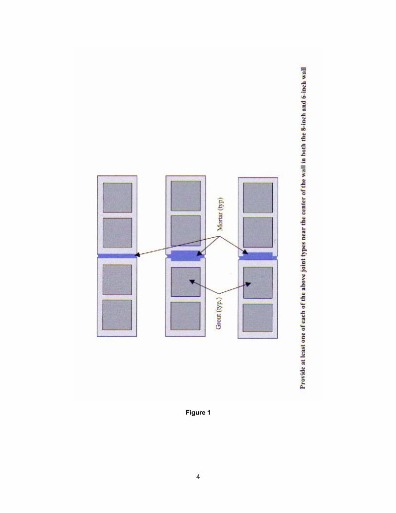
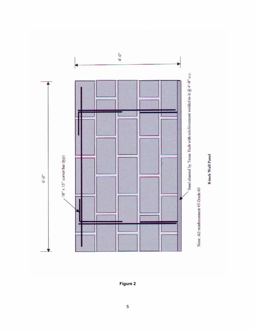
Series One: 4-ft. x 6-ft. test panel constructed with 8-in.CMU block layed with 3/8-in.
mortar joints of Type S masonry cement mortar, in accordance with ASTM C270 by the
Proportion Method. The masonry units included both solid end blocks and eared end
block, see Figure 1. Each masonry cell was grouted full with fine grout in accordance
with ASTM C476 by the Proportion Method. The head joint between the solid end blocks
and the eared blocks was bedded with Type S masonry cement mortar. No. 5 steel
reinforcing was placed at 4-ft. on center, refer to Figure 2.
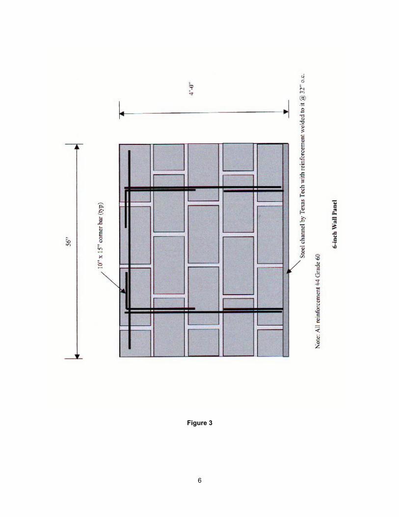
Series Two: 4-ft. x 4.67-ft. test constructed with 6-in.CMU block layed with 3/8-in.
mortar joints of Type S masonry cement mortar, in accordance with ASTM C270 by the
Proportion Method. The masonry units included only solid end blocks, see Figure 1.
Each masonry cell was grouted full with fine grout in accordance with ASTM C476 by the
Proportion Method. No. 4 steel reinforcing was placed at 32-in. on center, refer to
Figure 3.
3
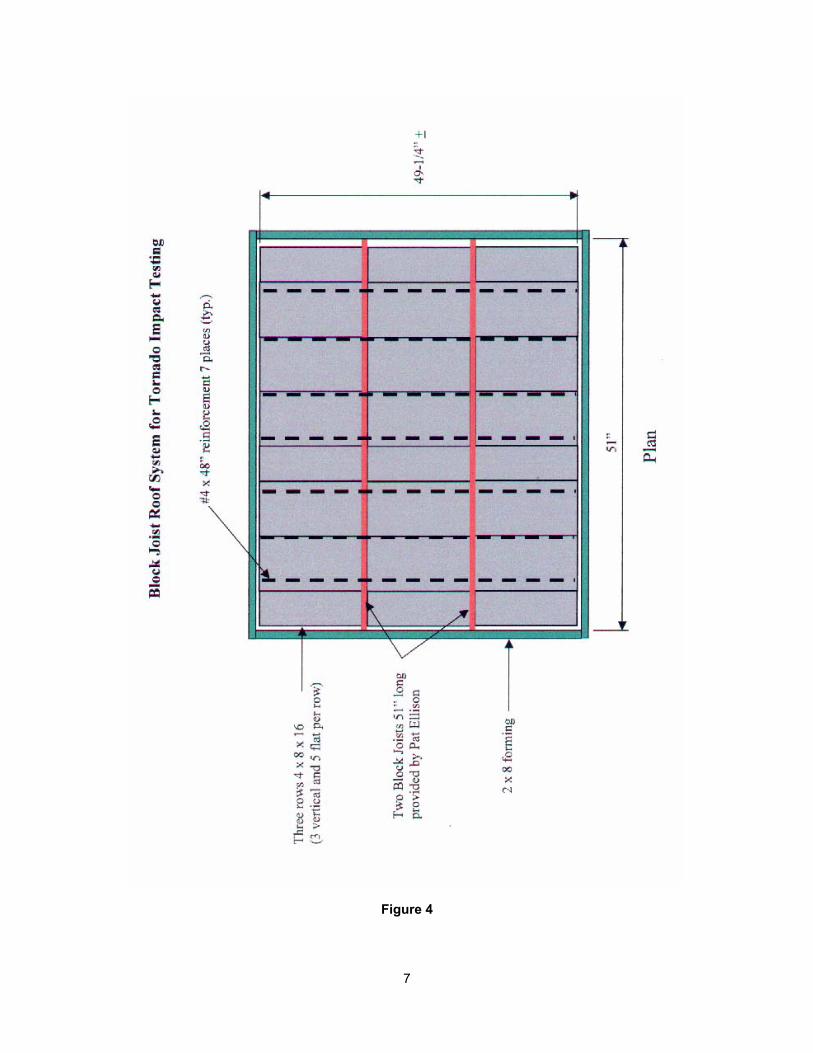
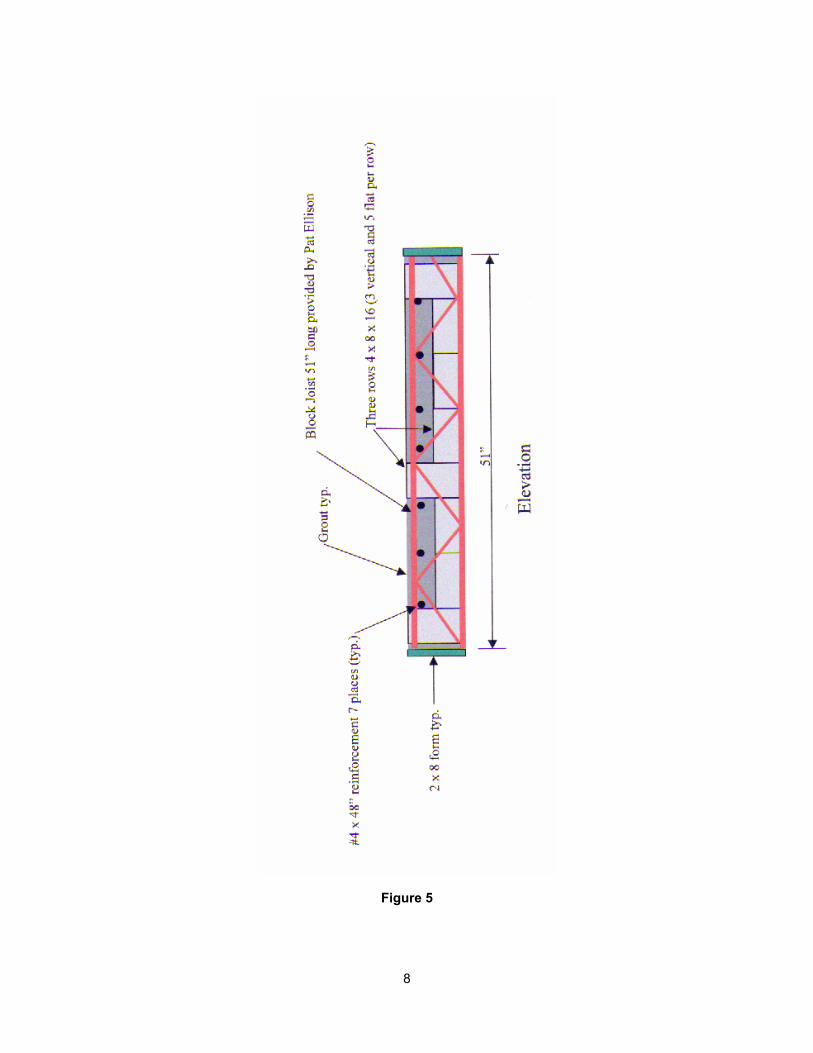
Series Three: 4-ft. x 4-ft. roof section utilizing three rows of solid CMU units, 4-in. x 8-in.
x 16-in. Three rows of block were layed on 51-in. long Block Joists with three blocks
installed vertically and five blocks layed horizontally. The roof section was grouted full
with fine grout in accordance with ASTM C476 by the Proportion Method. The panel was
further reinforced with 7- #4 rebars layed perpendicular to the joists, refer to Figures 4 &
5.
The missile criterion used for the tests was a 15-lb. 2x4-in. wood board traveling along the
board’s longitudinal axis, striking the panel perpendicular to the panel face. For test subjects inclined at
30 degrees or greater from the horizontal, the tornado test criterion uses this missile traveling at 100-mph
which corresponds to debris propelled horizontally by a 250-mph ground speed wind and is the criterion
used in designing for occupant protection. For test subjects inclined less than 30 degrees, the test
missile speed is 67-mph which related the missile dropped vertically by the 250-mph ground speed
tornado. Additional factors of safety are inherent in the criterion, since there is a very small probability
that a missile will be traveling along its axis and will strike a wall perpendicular to its surface.
A pressure test was not conducted. The missile criterion used in the test is consistent with the
guidelines of FEMA 320, “Taking Shelter from the Storm.”
4
Figure 1
5
Figure 2
6
Figure 3
7
Figure 4
8
Figure 5
9
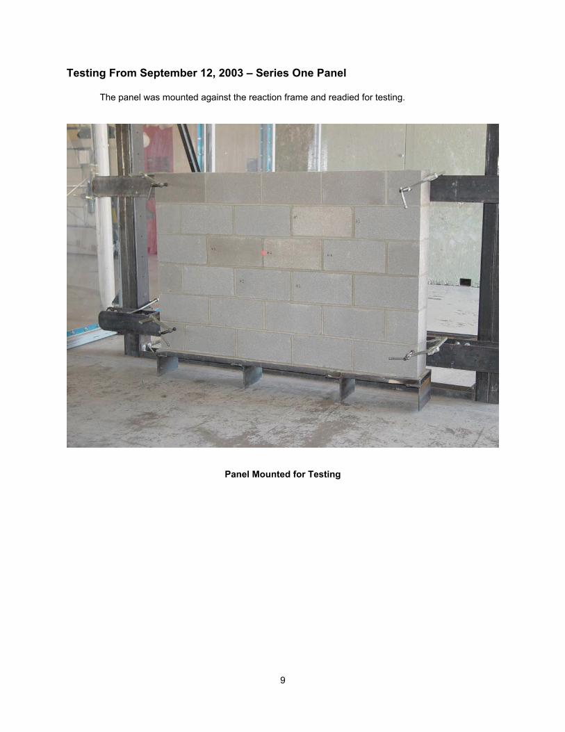
Testing From September 12, 2003 – Series One Panel
The panel was mounted against the reaction frame and readied for testing.
Panel Mounted for Testing
10
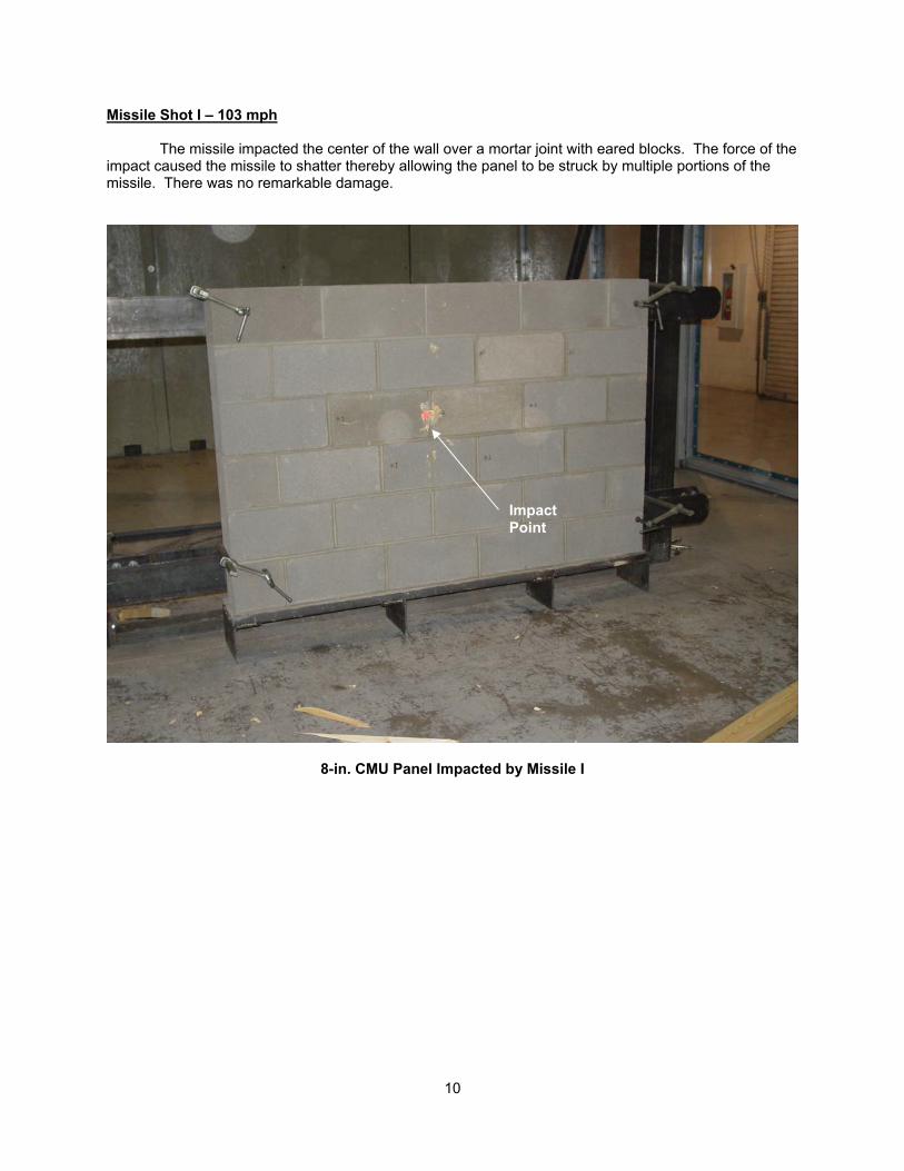
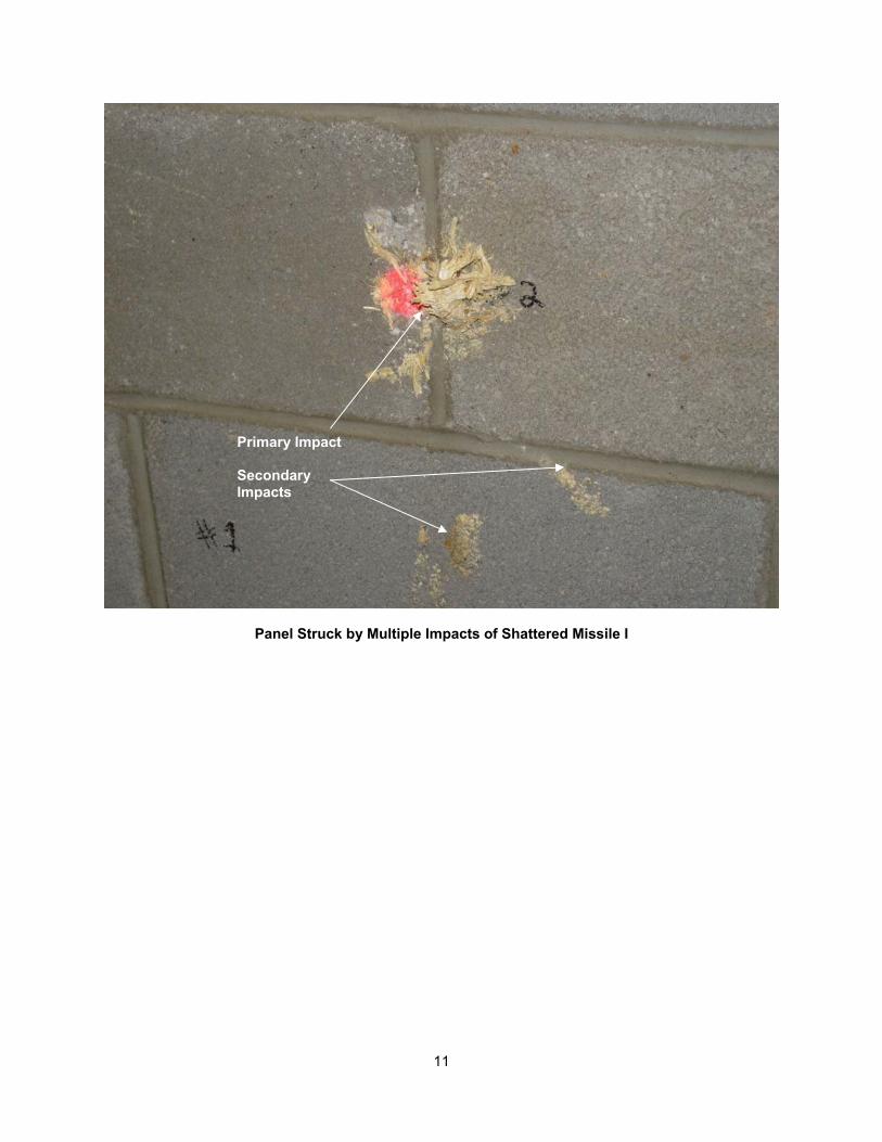
Missile Shot I – 103 mph The missile impacted the center of the wall over a mortar joint with eared blocks. The force of the impact caused the missile to shatter thereby allowing the panel to be struck by multiple portions of the missile. There was no remarkable damage.
8-in. CMU Panel Impacted by Missile I
Impact Point
11
Panel Struck by Multiple Impacts of Shattered Missile I
Primary Impact Secondary Impacts
12
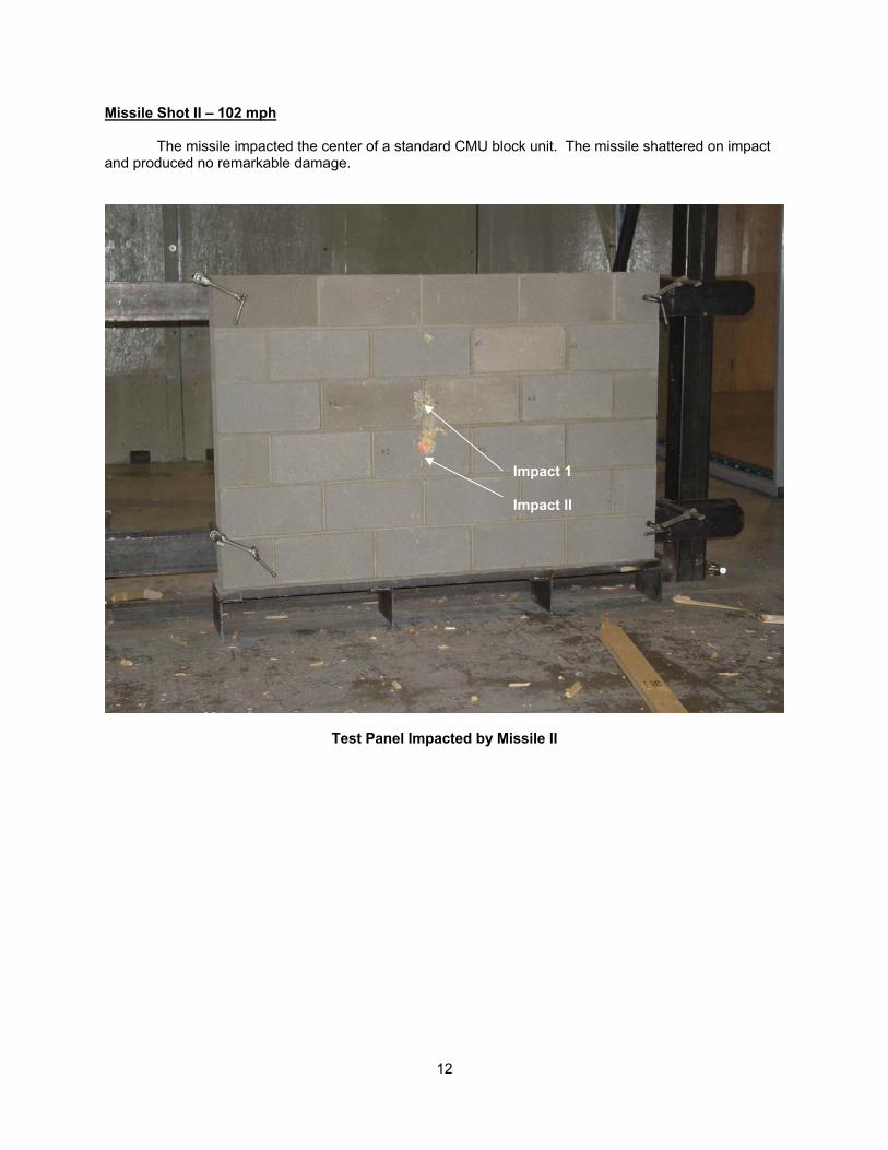
Missile Shot II – 102 mph The missile impacted the center of a standard CMU block unit. The missile shattered on impact and produced no remarkable damage.
Test Panel Impacted by Missile II
Impact 1 Impact II
13
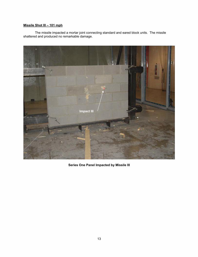
Missile Shot III – 101 mph The missile impacted a mortar joint connecting standard and eared block units. The missile shattered and produced no remarkable damage.
Series One Panel Impacted by Missile III
Impact III
14
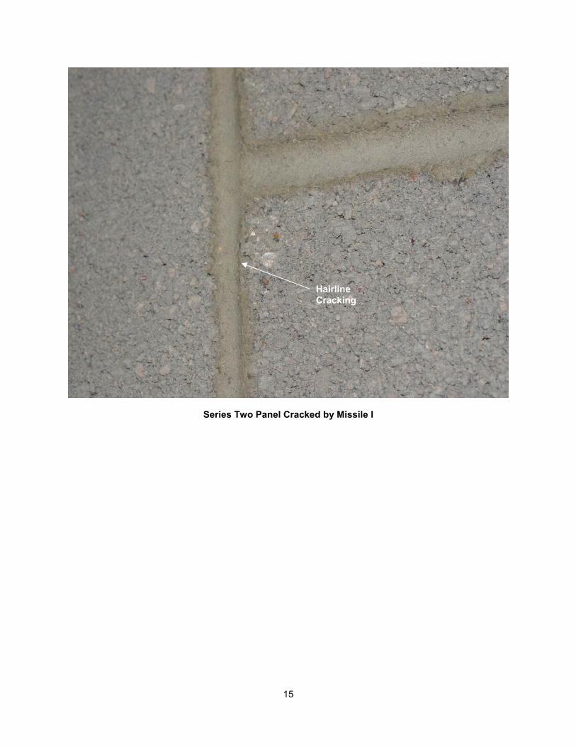
Testing From September 12, 2003 – Series Two Panel Missile Shot I – 101 mph The missile impacted the center of the 6-in. CMU block wall. The missile produced hairline vertical cracking through the mortar joint on the backside (safe side) of the panel directly above and below the impact point.
Series Two Panel after Impact
Impact Point
15
Series Two Panel Cracked by Missile I
Hairline Cracking
16
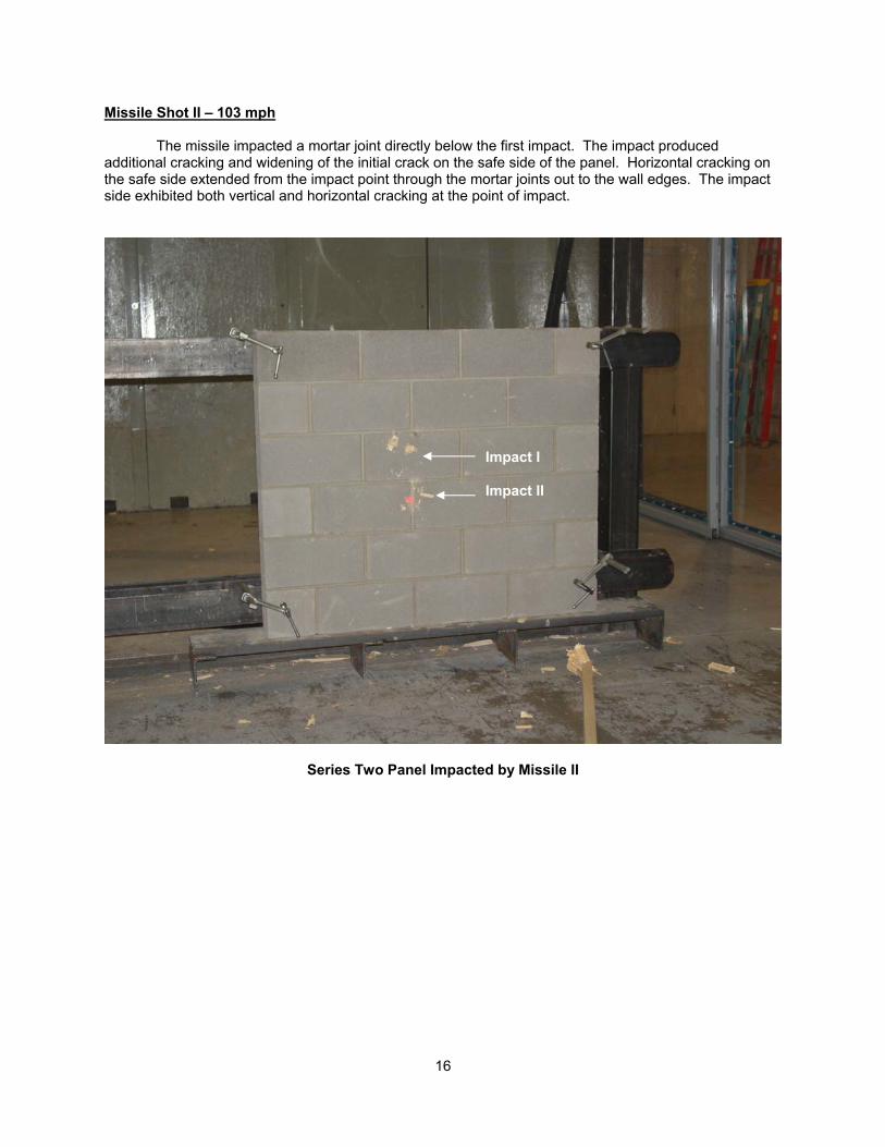
Missile Shot II – 103 mph The missile impacted a mortar joint directly below the first impact. The impact produced additional cracking and widening of the initial crack on the safe side of the panel. Horizontal cracking on the safe side extended from the impact point through the mortar joints out to the wall edges. The impact side exhibited both vertical and horizontal cracking at the point of impact.
Series Two Panel Impacted by Missile II
Impact I Impact II
17
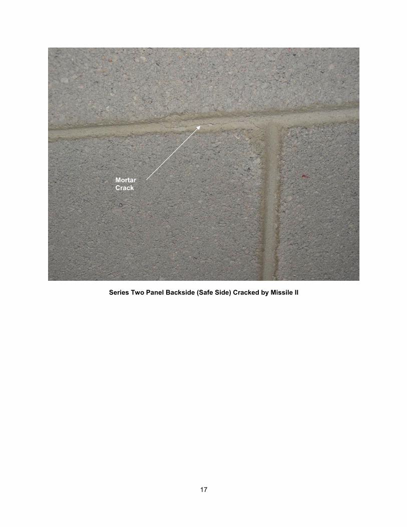
Series Two Panel Backside (Safe Side) Cracked by Missile II
Mortar Crack
18
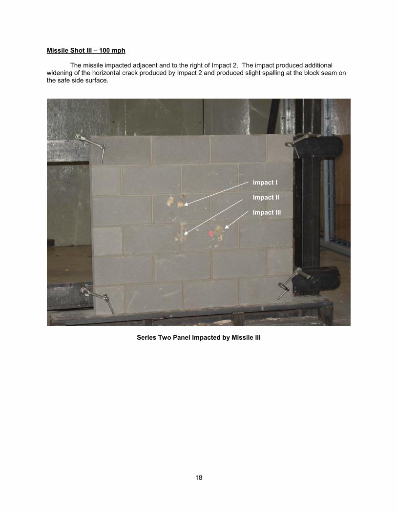
Missile Shot III – 100 mph The missile impacted adjacent and to the right of Impact 2. The impact produced additional widening of the horizontal crack produced by Impact 2 and produced slight spalling at the block seam on the safe side surface.
Series Two Panel Impacted by Missile III
Impact I Impact II Impact III
19
Series Three Panel Safe Side Cracked by Missile III
Horizontal Crack With Spalling
20
Testing From September 12, 2003 – Series Three Panel
Missile Shot I – 70 mph The Series Three Panel was a roof panel installed vertically for testing. The panel was impacted on the right center, adjacent the block joist. The impact produced no remarkable damage.
Series Three Panel Impacted Adjacent a Block Joist
Block Joist Impact I
21
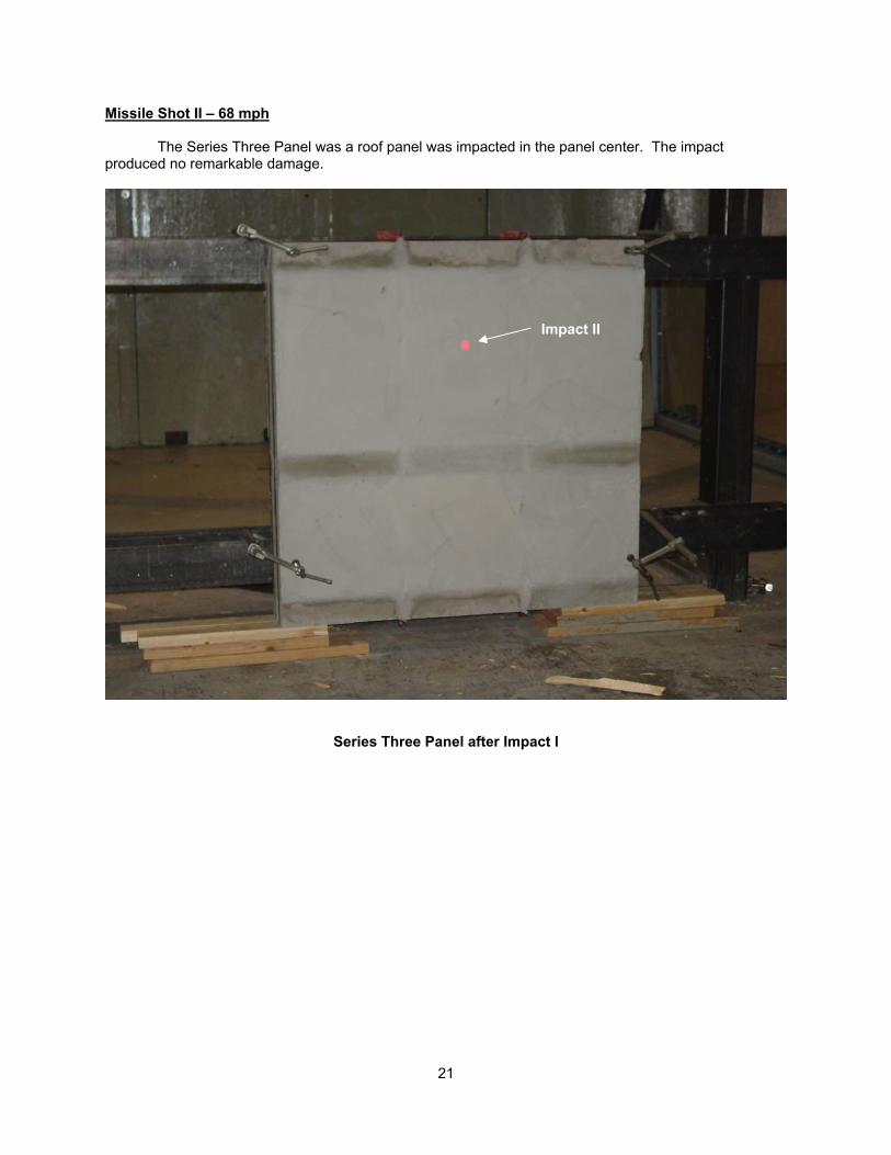
Missile Shot II – 68 mph The Series Three Panel was a roof panel was impacted in the panel center. The impact produced no remarkable damage.
Series Three Panel after Impact I
Impact II
22
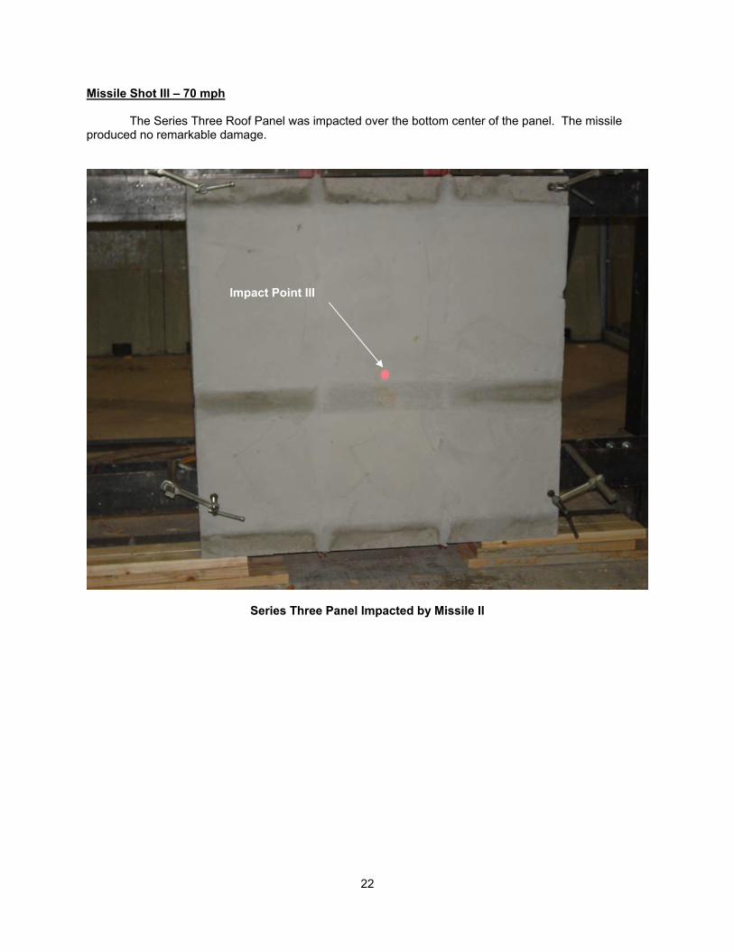
Missile Shot III – 70 mph The Series Three Roof Panel was impacted over the bottom center of the panel. The missile produced no remarkable damage.
Series Three Panel Impacted by Missile II
Impact Point III
23
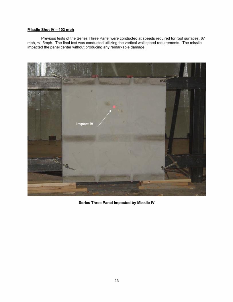
Missile Shot IV – 103 mph Previous tests of the Series Three Panel were conducted at speeds required for roof surfaces, 67 mph, +/- 5mph. The final test was conducted utilizing the vertical wall speed requirements. The missile impacted the panel center without producing any remarkable damage.
Series Three Panel Impacted by Missile IV
Impact IV
24
Conclusions Within the bounds of reasonable engineering and technical certainty, and subject to change if additional information becomes available, the following is my professional opinion:
Tests on the Series One 8-in. CMU wall panel, the Series Two 6-in. CMU wall panel and the Series Three CMU roof panel were successful. The test missile neither perforated the test subjects or produced hazardous spalling on the safe side of the wall. The 15-lb. 2x4 missile traveling horizontally at 100 mph is required by FEMA 320 and relates to a missile propelled by a 250 mph ground speed tornado. The vertical test missile traveling at 67 mph relates to the missile dropped by a 250 mph ground speed tornado. The Series One, Two and Three panels are consistent with the debris impact resistance required by the FEMA 320, “Taking Shelter from the Storm” guidelines.
_________________________ Larry J. Tanner, P.E.
Use of Testing Report and TTU and WISE Logos The written report and supplemental photos and/or videos may be referenced or distributed by your company. But, Texas Tech University cannot endorse products nor can the name of the University or any of its units or personnel be used in advertising without first securing written permission from the University. Any misuse or misrepresentation of the report and/or pictures will result in action being taken by the University against the responsible parties. Storm shelter manufacturers or producers who have had products tested at Texas Tech University can use the Texas Tech University Wind Engineering logo provided they conform to the following:
I. The Texas Tech University Wind Engineering logo may not be so prominent as to mislead the public or unduly play upon the Texas Tech University Wind Engineering name.
II. Whenever the logo is used one of the two alternative statements below is to be employed in the text:
Alternate 1 – whole shelter
The use of the Texas Tech University Wind Engineering logo signifies that the complete shelter structure was tested and successfully passed missile impact resistance tests at Texas Tech University.
Alternate 2 - shelter component
The use of the Texas Tech University Wind Engineering logo does not signify that the entire shelter structure was tested at Texas Tech, but rather only [shelter component – name explicitly] was tested and successfully passed missile impact resistance tests at Texas Tech University.
III. All advertising and promotional texts containing the use of the Texas Tech University Wind Engineering logo are to be presented to the Texas Tech University Office of Technology Transfer and Intellectual Property for review and approval before distribution.
Texas Tech University will challenge any use of the Texas Tech University Wind Engineering logo that does not conform to the above standards.