INVESTIGATIONS OF CONTROLLING PROPAGATION CHARACTERISTICS USING TRANSMITTING ANTENNA ARRAY IN MOBILE MICROCELLULAR ENVIRONMENT Hassan M. El-Sallabi and Pertti Vainikainen Radio Laboratory, Institute of Radio Communications (IRC) Helsinki University of Technology P. O. Box 3000, FIN-02015 HUT, Finland Tel: +358 9 451 22 55, E-mail: hel radio.hut.fi ABSTRACT This work proposes a propagation control technique for mobile communications in microcellular environment. Transmitting array antennas at the base station are utilized for controlling propagation characteristics. The propagation control technique can be used for interference reduction between neighboring cells and controlling the coverage area size (e.g., controlling propagation slope). Five propagation control methods are suggested. Three schemes are tested here, the antenna arrangement, the phase excitations and the displacements between antennas. INTRODUCTION The increasing demand for mobile communication services and a limited spectrum allocated for such services have led to the concept of microcell [1]. In microcellular systems the BS antennas are placed below the surrounding buildings in order to confine propagation area. Thus, most of the received power propagates along the street. In other words, the coverage area extends along the street; hence the name “street microcell” is often used. In street microcellular systems, the cell coverage area depends on the positions of the surrounding buildings. The small coverage area and high frequency reuse rate which is determined by the carrier to interference ratio (C/I) to be greater than or equal to certain value, allows increase in the communication capacity. One way to increase system capacity is the reduction of cell size and signal strength that affects on neighboring cells as interference. This work considers a propagation control technique in which it attenuates the received power at a dependence of less than 1/r 2 , where r is the propagation distance, results in interference and cell size reduction (i.e., cell boundary). In [2], the principle of break point is used in defining cell boundaries. The propagation control technique proposed in this work is the use of transmitting antenna arrays at the base station. Five possible control methods are presented in this work. They can be used individually or some combination between them. In addition, the propagation characteristics of the proposed schemes are analyzed. Multipath fading is important method for characterizing channel characteristics that can be related to system performance measure. PROPAGATION CONTROL AND MODEL The propagation control proposed in this work is originated for antenna array theory. Array theory is based on a group of similar antennas. In this case the effect of antenna group to the radiation pattern can be separated from the effect of the single element. The total field of the array is determined by the vector addition of the field of the individual elements. To provide very directive pattern (i.e., to control propagation), it is necessary that the fields from the elements of the array interfere constructively in the desired direction and destructively in the remaining space. In array of identical elements, there are five controls that can be used to shape the overall pattern of the antenna that control the propagation. These are: 1) array geometrical configuration (linear, plannar, spherical, etc.), 2) the relative displacement between elements, 3) the relative pattern of the individual elements, 4) excitation amplitude of each element, 5) excitation phase of each element. The amplitude and phase differences are electrically tunable and the tuning can be adaptively implemented with digital signal processor. The relative displacement between elements is, in practice, a fixed constant, which however can be considered as a free parameter at the design stage of the array. The fixed radiation pattern of a base station antenna assists network and frequency planning of mobile communication networks, since it is often necessary to minimize the interference from the neighboring cells of a given base station. Using these schemes, size of coverage area can be controlled as well as propagation characteristics.
Transcript
INVESTIGATIONS OF CONTROLLING PROPAGATION CHARACTERISTICS USING TRANSMITTING ANTENNA ARRAY IN MOBILE MICROCELLULAR ENVIRONMENT
Hassan M. El-Sallabi and Pertti Vainikainen
Radio Laboratory, Institute of Radio Communications (IRC) Helsinki University of Technology
P. O. Box 3000, FIN-02015 HUT, Finland Tel: +358 9 451 22 55, E-mail: hel#radio.hut.fi
ABSTRACT This work proposes a propagation control technique for mobile communications in microcellular environment. Transmitting array antennas at the base station are utilized for controlling propagation characteristics. The propagation control technique can be used for interference reduction between neighboring cells and controlling the coverage area size (e.g., controlling propagation slope). Five propagation control methods are suggested. Three schemes are tested here, the antenna arrangement, the phase excitations and the displacements between antennas. INTRODUCTION The increasing demand for mobile communication services and a limited spectrum allocated for such services have led to the concept of microcell [1]. In microcellular systems the BS antennas are placed below the surrounding buildings in order to confine propagation area. Thus, most of the received power propagates along the street. In other words, the coverage area extends along the street; hence the name “street microcell” is often used. In street microcellular systems, the cell coverage area depends on the positions of the surrounding buildings. The small coverage area and high frequency reuse rate which is determined by the carrier to interference ratio (C/I) to be greater than or equal to certain value, allows increase in the communication capacity. One way to increase system capacity is the reduction of cell size and signal strength that affects on neighboring cells as interference. This work considers a propagation control technique in which it attenuates the received power at a dependence of less than 1/r2, where r is the propagation distance, results in interference and cell size reduction (i.e., cell boundary). In [2], the principle of break point is used in defining cell boundaries. The propagation control technique proposed in this work is the use of transmitting antenna arrays at the base station. Five possible control methods are presented in this work. They can be used individually or some combination between them. In addition, the propagation characteristics of the proposed schemes are analyzed. Multipath fading is important method for characterizing channel characteristics that can be related to system performance measure. PROPAGATION CONTROL AND MODEL The propagation control proposed in this work is originated for antenna array theory. Array theory is based on a group of similar antennas. In this case the effect of antenna group to the radiation pattern can be separated from the effect of the single element. The total field of the array is determined by the vector addition of the field of the individual elements. To provide very directive pattern (i.e., to control propagation), it is necessary that the fields from the elements of the array interfere constructively in the desired direction and destructively in the remaining space. In array of identical elements, there are five controls that can be used to shape the overall pattern of the antenna that control the propagation. These are: 1) array geometrical configuration (linear, plannar, spherical, etc.), 2) the relative displacement between elements, 3) the relative pattern of the individual elements, 4) excitation amplitude of each element, 5) excitation phase of each element. The amplitude and phase differences are electrically tunable and the tuning can be adaptively implemented with digital signal processor. The relative displacement between elements is, in practice, a fixed constant, which however can be considered as a free parameter at the design stage of the array. The fixed radiation pattern of a base station antenna assists network and frequency planning of mobile communication networks, since it is often necessary to minimize the interference from the neighboring cells of a given base station. Using these schemes, size of coverage area can be controlled as well as propagation characteristics.
Characterization of a propagation channel is very important in evaluation of channel impairments. To characterize the microcell propagation, uniform geometrical theory of diffraction (UTD) and ray-based techniques are often employed as a theoretical prediction model because it provides much more accurate solution than other models. In this section, for a city street with any number of crossing streets with different widths, a theoretical model [3] used to obtain the received power is described. The needed database for the model is minimal. For 2N transmitting antennas, the
transmitted power is set N2/1 of the single antenna BS power for each antenna element. The received power at the receiving antenna of the mobile station (MS) due to the multiple transmitting antennas at the base station (BS) is considered. The received power, from all rays that strike wall up to 0 times, is given by
( ) ( ) ( )( )2
0
1
0
2
0
)1/(2
mSSfHP
P rAFimgS
Nt
r Π−+Π= ∑∑∑===
δu0
(1)
where
( )i
jkriHHiVVi reH i πλ 4,
−Γ= , (2)
( )
>=
=Π0,1
0,0
χχ
χ , (3)
( ) ( )[ ]∏=
++=N
n
dkujnrAF
nnreIf1
.1 δu (4)
where Hi is the transfer function of the ith ray between BS antenna element at the origin and MS antenna, m is the
reflection order, λ is the wavelength, k is the wave number, δ(•) is the delta function, iHHiVV ,Γ is the ith ray co-
polarized reflection coefficient for vertical and horizontal polarization, respectively, it is a function of the well-known Fresnel reflection coefficients for vertical and horizontal polarization for ground and wall-reflections. The parameters S
and g are for inclusion of the sidewalls and ground reflections, respectively. The )( rAFf u is the array factor for array
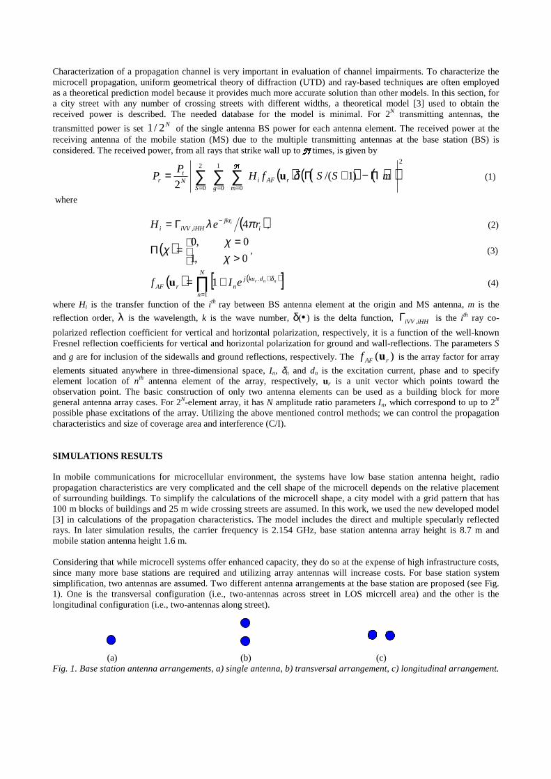
elements situated anywhere in three-dimensional space, In, δn and dn is the excitation current, phase and to specify element location of nth antenna element of the array, respectively, ur is a unit vector which points toward the observation point. The basic construction of only two antenna elements can be used as a building block for more general antenna array cases. For 2N-element array, it has N amplitude ratio parameters In, which correspond to up to 2N possible phase excitations of the array. Utilizing the above mentioned control methods; we can control the propagation characteristics and size of coverage area and interference (C/I). SIMULATIONS RESULTS In mobile communications for microcellular environment, the systems have low base station antenna height, radio propagation characteristics are very complicated and the cell shape of the microcell depends on the relative placement of surrounding buildings. To simplify the calculations of the microcell shape, a city model with a grid pattern that has 100 m blocks of buildings and 25 m wide crossing streets are assumed. In this work, we used the new developed model [3] in calculations of the propagation characteristics. The model includes the direct and multiple specularly reflected rays. In later simulation results, the carrier frequency is 2.154 GHz, base station antenna array height is 8.7 m and mobile station antenna height 1.6 m. Considering that while microcell systems offer enhanced capacity, they do so at the expense of high infrastructure costs, since many more base stations are required and utilizing array antennas will increase costs. For base station system simplification, two antennas are assumed. Two different antenna arrangements at the base station are proposed (see Fig. 1). One is the transversal configuration (i.e., two-antennas across street in LOS micrcell area) and the other is the longitudinal configuration (i.e., two-antennas along street). (a) (b) (c) Fig. 1. Base station antenna arrangements, a) single antenna, b) transversal arrangement, c) longitudinal arrangement.
In street microcellular systems, the cell coverage area depends on the positions of the surroundings. The minimum signal strength and the carrier to interference ratio (C/I) are usually used to determine the cell boundary. For the chosen microcellular environment and minimum signal reception level of –115 dBm is the used criteria. One can see from Fig. 2a that this level is obtained at around 800 m, which is related to the cell coverage area. To reduce the coverage area, transmitting antenna array at the base station can be used. Fig. 2b & 2c represent control of coverage area by using two
antennas separated by 2λ transversally (across street) and longitudinally (along street), respectively. The same
amplitudes and the same phase excite the two antennas, longitudinally configured; the opposite phase is used for the case of the transversal arrangement. For single antenna BS, Fig. 2a, the interference pattern are well above the 1/r2 reference over most of the distance beyond about 200 m. Faster decay with distance can be seen in the case of the transversal array, Fig. 2b. An even faster decay with distance can be seen in Fig. 2c, when longitudinal arrays are used. In Fig. 2, differences in received signal level are based on the differences in the antenna patterns. For the case of transversal arrangements, Fig. 2b, with same excitation phase and currents on the two antennas, it is noted (not shown here) that the received signal level is higher than that of single antenna by about 3 dB due to constructive interference.
0 400 800 1200 1600 2000−170
−150
−130
−110
−90
Distance, m
Re
ce
ive
d s
ign
al le
ve
l, d
Bm
M−ray model Fall off 1/r2 Threshold −115 dBm
0 100 200 300 400 500 600 700 800−170
−160
−150
−140
−130
−120
−110
−100
−90
−80
Distance, m
Re
ce
ive
d s
ign
al le
ve
l, d
Bm
M−ray Model 1/r2 Fall off
0 100 200 300 400 500 600 700 800−170
−160
−150
−140
−130
−120
−110
−100
−90
−80
Distance, m
Re
ce
ive
d s
ign
al le
ve
l, d
Bm
M−ray Model 1/r2 Fall off
(a) (b) (c) Fig. 2. Received power at MS antenna for a) single BS antenna, b) two BS antennas, transversal array, c) two BS antennas, longitudinal array. In order to investigate the effect of excitation phase difference between the two antennas, the longitudinal arrangement
of base station antennas displaced by 2λ are excited with a phase difference from 0o to 180o. Fig. 3 shows the
received power at the MS due to the two transmitting BS antennas. The received power is shown for a minimum of –115 dBm, which is related to the cell boundaries. It can readily be seen that as the phase difference increases, the received power increases and the cell boundary increases. For the excitation phase difference of 0o, minimum received power (i.e., -115 dBm) is at distance around 100 m; this distance increases with increasing the excitation phase difference. Thus, it is possible to control the size of the coverage area with changing the phase difference between two
antennas displaced by 2λ .
For investigating the effect of displacement distance between two transmitting antennas at the base station, transversal
configuration of two antennas is tested. The separation distance varies from 2λ to λ4 and the two antennas are
excited with opposite phase. Fig. 4 shows the received power at the MS due to transversally arranged two antennas. One can see that increasing separation distance of transversally arranged two antennas, with opposite phase excitation, results in higher received level at the MS. Thus, it is possible to control the cell boundary by changing the separation distance. However, the element separation is, in practice, a fixed parameter, which can be considered as free parameter at the design stage. For network point of view, controlling of the coverage area via phase excitation is easier and is electrically tunable and the tuning can be can be adaptively implemented with a digital signal processor to control interference on neighboring cells.
030
6090
120150
1800
200400
600800
−115
−110
−105
−100
−95
−90
−85
−80
Distance, mPhase shift, deg.
Rec
eive
d si
gnal
leve
l, dB
m
Fig. 3. Received power at MS for two longitudinally arranged transmitting BS antennas.
0.51
1.52
2.53
3.54 0
200
400
600
800
−110
−100
−90
−80
Distance, mAntennas separation, λ
Rece
ived
signa
l leve
l, dB
m
Fig. 4. Received power at MS for two transversally arranged transmitting BS antennas.
Fig. 5 depicts each antenna arrangement multipath fading at MS located at 100 m and 300 m apart from the transmitting antenna. The range of variation of fading signals at 100 m from the transmitting antennas are narrower and more sever than those of locations at 300 m from the base station antenna(s). It is due to spatial path difference are larger and even larger angular distribution [4]. In Fig. 5a, it can readily be seen that the variation of the signal fading of both single transmitting antenna and two transversally displaced antennas with opposite excitation phases are generally similar but quite different from that of longitudinal arrangement. The signal fading of longitudinal arrangement is less severe than other two cases.
94 96 98 100 102 104 106−150
−140
−130
−120
−110
−100
Distance, m
Rec
eive
d si
gnal
leve
l, dB
m
Single antenna Transversal arragement Longitudinal arrangement
Fig. 5. Multipath fading at MS, (a) 100 m apart from BS, (b) 300 m apart from BS. CONCLUSION In this work, we propose a propagation control technique originated in antenna array theory. It is shown that it is possible to control coverage area size, which results in interference reduction, and propagation characteristics in microcellular environment. The propagation control methods are based on utilizing transmitting antenna array at the base station. Five different control methods are proposed. Three schemes are tested here, the antenna arrangement, the phase excitations and the displacements between antennas. REFERENCES [1] H. L. Bertoni, W. Honcharenko, L.R. Maciel and H.H. Xia, “UHF propagation for wireless personal communications,” Proc.
IEEE, Vol. 82, 1333--1359, Sep. 1994. [2] Feuerstein, M. J., K.L. Blackard, T.S. Rappaport, S.Y. Seidel, and H.H. Xia, "Path loss, delay spread, and outage models as
functions of antenna height for microcellular system design," IEEE Trans. Veh. Technol., Vol. 43, 487--498, Aug. 1994. [3] H. M. El-Sallabi and P. Vainikainen, “Three-dimensional physical modeling of wideband propagation in a city street for
microcellular communication,” unpublished. [4] Hassan. M. El-Sallabi and P. Vainikainen, "Modeling and simulation of wideband radio channel characterization for an urban
line-of-sight microcell," in Proc. of IEEE Vehicul. Technolg. Conference VTC’99 falls, 19-22, Sep. 1999, pp. 2383-2387, Amseterdam, the Netherland.